1985 FORD GRANADA key
[x] Cancel search: keyPage 12 of 255
engine valve clearances must be correct. The
ignition system must also be in good
condition.
3Mixture adjustment is not usual on a routine
basis. If the CO level is incorrect, proceed as
follows.
4Connect the exhaust gas analyser as
instructed by the manufacturers.
5Raise the engine speed to 3000 rpm
approximately and hold it at this speed for
30 seconds, then allow it to idle. Repeat this
procedure every 60 seconds until adjustment
is complete.6Read the CO level when it has stabilised
after the 3000 rpm burst. The desired level is
given in the Specifications of Chapter 4
(Pierburg 2V carburettor).
7If the idle mixture needs adjustment, turn
the mixture adjusting screw. The screw may
be covered by a tamperproof plug.
8Recheck the idle speed after adjusting the
mixture.
9Stop the engine and disconnect the test
gear. 10Fit a new tamperproof plug to the mixture
adjusting screw if required.
2.0 litre SOHC engine
11If mixture adjustment is required, proceed
as described for the 1.8 litre engine above.
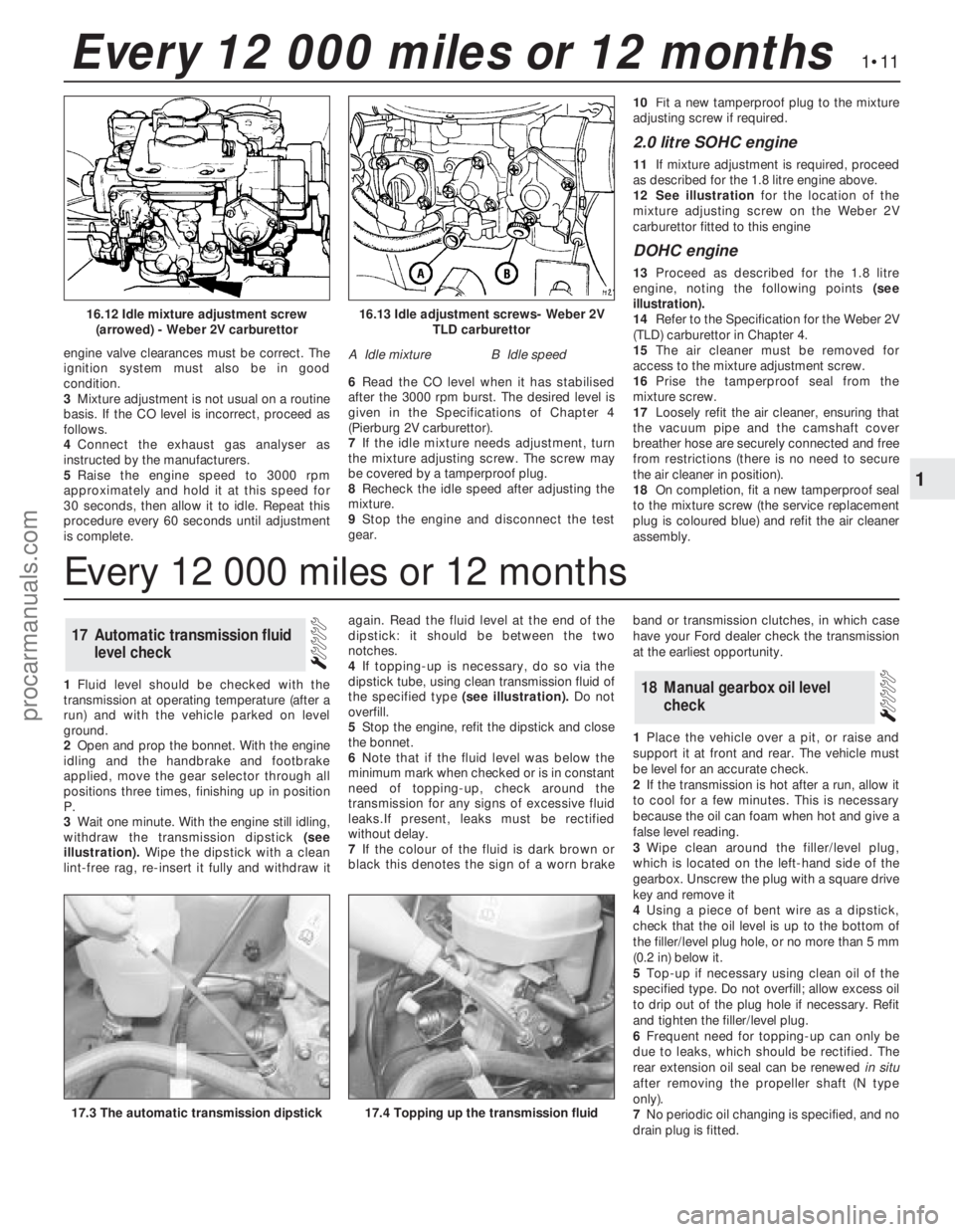
12See illustrationfor the location of the
mixture adjusting screw on the Weber 2V
carburettor fitted to this engine
DOHC engine
13Proceed as described for the 1.8 litre
engine, noting the following points (see
illustration).
14Refer to the Specification for the Weber 2V
(TLD) carburettor in Chapter 4.
15The air cleaner must be removed for
access to the mixture adjustment screw.
16Prise the tamperproof seal from the
mixture screw.
17Loosely refit the air cleaner, ensuring that
the vacuum pipe and the camshaft cover
breather hose are securely connected and free
from restrictions (there is no need to secure
the air cleaner in position).
18On completion, fit a new tamperproof seal
to the mixture screw (the service replacement
plug is coloured blue) and refit the air cleaner
assembly.
1Fluid level should be checked with the
transmission at operating temperature (after a
run) and with the vehicle parked on level
ground.
2Open and prop the bonnet. With the engine
idling and the handbrake and footbrake
applied, move the gear selector through all
positions three times, finishing up in position
P.
3Wait one minute. With the engine still idling,
withdraw the transmission dipstick (see
illustration).Wipe the dipstick with a clean
lint-free rag, re-insert it fully and withdraw itagain. Read the fluid level at the end of the
dipstick: it should be between the two
notches.
4If topping-up is necessary, do so via the
dipstick tube, using clean transmission fluid of
the specified type (see illustration).Do not
overfill.
5Stop the engine, refit the dipstick and close
the bonnet.
6Note that if the fluid level was below the
minimum mark when checked or is in constant
need oftopping-up, check around the
transmission for any signs of excessive fluid
leaks.If present, leaks must be rectified
without delay.
7If the colour of the fluid is dark brown or
black this denotes the sign of a worn brakeband or transmission clutches, in which case
have your Ford dealer check the transmission
at the earliest opportunity.
1Place the vehicle over a pit, or raise and
support it at front and rear. The vehicle must
be level for an accurate check.
2If the transmission is hot after a run, allow it
to cool for a few minutes. This is necessary
because the oil can foam when hot and give a
false level reading.
3Wipe clean around the filler/level plug,
which is located on the left-hand side of the
gearbox. Unscrew the plug with a square drive
key and remove it
4Using a piece of bent wire as a dipstick,
check that the oil level is up to the bottom of
the filler/level plug hole, or no more than 5 mm
(0.2 in) below it.
5Top-up if necessary using clean oil of the
specified type. Do not overfill; allow excess oil
to drip out of the plug hole if necessary. Refit
and tighten the filler/level plug.
6Frequent need for topping-up can only be
due to leaks, which should be rectified. The
rear extension oil seal can be renewedin situ
after removing the propeller shaft (N type
only).
7No periodic oil changing is specified, and no
drain plug is fitted.
18Manual gearbox oil level
check
17Automatic transmission fluid
level check
1•11
1
Every 12 000 miles or 12 months
16.13 Idle adjustment screws- Weber 2V
TLD carburettor
A Idle mixtureB Idle speed
16.12 Idle mixture adjustment screw
(arrowed) - Weber 2V carburettor
17.4 Topping up the transmission fluid17.3 The automatic transmission dipstick
Every 12 000 miles or 12 months
procarmanuals.com
Page 16 of 255
1Remove the radiator grille being careful not
to damage the condenser fins.
2Check the refrigerant charge as follows. The
engine should be cold and the ambient
temperature should be between 18°and 25°C
(64°and 77°F).
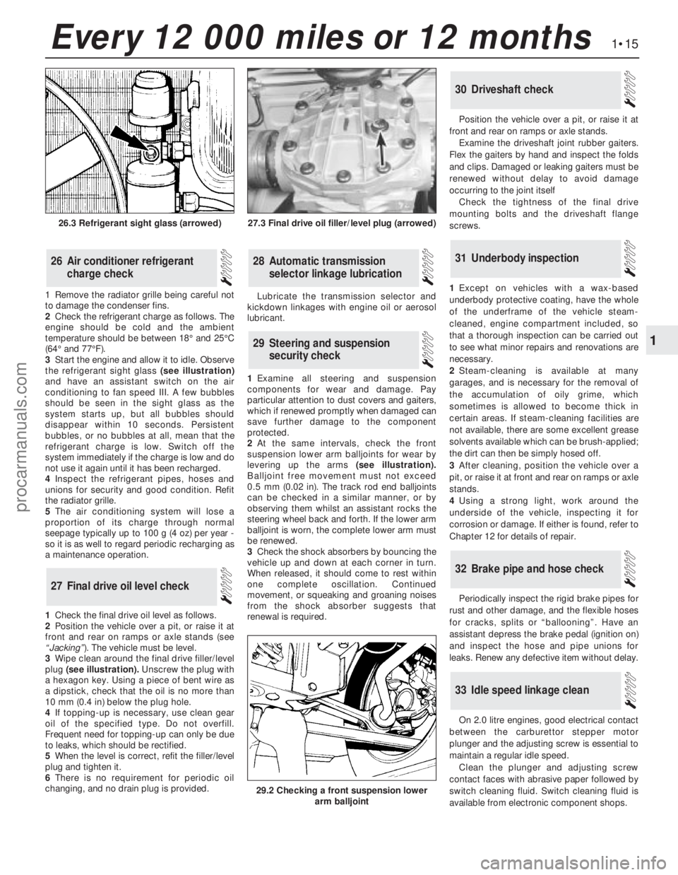
3Start the engine and allow it to idle. Observe
the refrigerant sight glass(see illustration)
and have an assistant switch on the air
conditioning to fan speed III. A few bubbles
should be seen in the sight glass as the
system starts up, but all bubbles should
disappear within 10 seconds. Persistent
bubbles, or no bubbles at all, mean that the
refrigerant charge is low. Switch off the
system immediately if the charge is low and do
not use it again until it has been recharged.
4Inspect the refrigerant pipes, hoses and
unions for security and good condition. Refit
the radiator grille.
5The air conditioning system will lose a
proportion of its charge through normal
seepage typically up to 100 g (4 oz) per year -
so it is as well to regard periodic recharging as
a maintenance operation.
1Check the final drive oil level as follows.
2Position the vehicle over a pit, or raise it at
front and rear on ramps or axle stands (see
“Jacking”). The vehicle must be level.
3Wipe clean around the final drive filler/level
plug (see illustration).Unscrew the plug with
a hexagon key. Using a piece of bent wire as
a dipstick, check that the oil is no more than
10 mm (0.4 in) below the plug hole.
4If topping-up is necessary, use clean gear
oil of the specified type. Do not overfill.
Frequent need for topping-up can only be due
to leaks, which should be rectified.
5When the level is correct, refit the filler/level
plug and tighten it.
6There is no requirement for periodic oil
changing, and no drain plug is provided. Lubricate the transmission selector and
kickdown linkages with engine oil or aerosol
lubricant.
1Examine all steering and suspension
components for wear and damage. Pay
particular attention to dust covers and gaiters,
which if renewed promptly when damaged can
save further damage to the component
protected.
2At the same intervals, check the front
suspension lower arm balljoints for wear by
levering up the arms(see illustration).
Balljoint free movement must not exceed
0.5 mm (0.02 in). The track rod end balljoints
can be checked in a similar manner, or by
observing them whilst an assistant rocks the
steering wheel back and forth. If the lower arm
balljoint is worn, the complete lower arm must
be renewed.
3Check the shock absorbers by bouncing the
vehicle up and down at each corner in turn.
When released, it should come to rest within
one complete oscillation. Continued
movement, or squeaking and groaning noises
from the shock absorber suggests that
renewal is required.Position the vehicle over a pit, or raise it at
front and rear on ramps or axle stands.
Examine the driveshaft joint rubber gaiters.
Flex the gaiters by hand and inspect the folds
and clips. Damaged or leaking gaiters must be
renewed without delay to avoid damage
occurring to the joint itself
Check the tightness of the final drive
mounting bolts and the driveshaft flange
screws.
1Except on vehicles with a wax-based
underbody protective coating, have the whole
of the underframe of the vehicle steam-
cleaned, engine compartment included, so
that a thorough inspection can be carried out
to see what minor repairs and renovations are
necessary.
2Steam-cleaning is available at many
garages, and is necessary for the removal of
the accumulation of oily grime, which
sometimes is allowed to become thick in
certain areas. If steam-cleaning facilities are
not available, there are some excellent grease
solvents available which can be brush-applied;
the dirt can then be simply hosed off.
3After cleaning, position the vehicle over a
pit, or raise it at front and rear on ramps or axle
stands.
4Using a strong light, work around the
underside of the vehicle, inspecting it for
corrosion or damage. If either is found, refer to
Chapter 12 for details of repair.
Periodically inspect the rigid brake pipes for
rust and other damage, and the flexible hoses
for cracks, splits or “ballooning”. Have an
assistant depress the brake pedal (ignition on)
and inspect the hose and pipe unions for
leaks. Renew any defective item without delay.
On 2.0 litre engines, good electrical contact
between the carburettor stepper motor
plunger and the adjusting screw is essential to
maintain a regular idle speed.
Clean the plunger and adjusting screw
contact faces with abrasive paper followed by
switch cleaning fluid. Switch cleaning fluid is
available from electronic component shops.
33Idle speed linkage clean
32Brake pipe and hose check
31Underbody inspection
30Driveshaft check
29Steering and suspension
security check
28Automatic transmission
selector linkage lubrication
27Final drive oil level check
26Air conditioner refrigerant
charge check
1•15
1
Every 12 000 miles or 12 months
27.3 Final drive oil filler/level plug (arrowed)
29.2 Checking a front suspension lower
arm balljoint
26.3 Refrigerant sight glass (arrowed)
procarmanuals.com
Page 19 of 255
distributor cap, making a sketch if necessary
so that they can be reconnected to the same
terminals. Remove the leads.
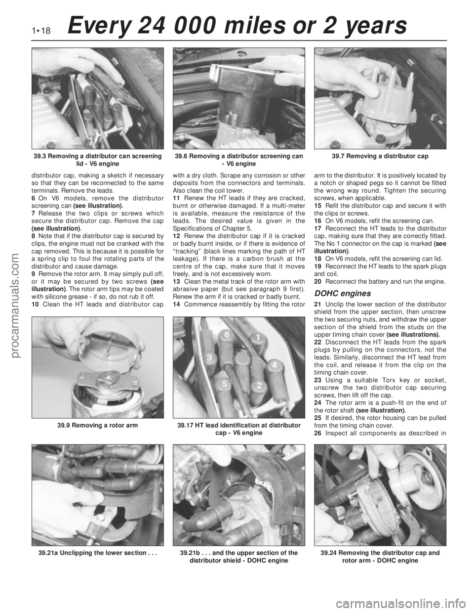
6On V6 models, remove the distributor
screening can (see illustration).
7Release the two clips or screws which
secure the distributor cap. Remove the cap
(see illustration).
8Note that if the distributor cap is secured by
clips, the engine must not be cranked with the
cap removed. This is because it is possible for
a spring clip to foul the rotating parts of the
distributor and cause damage.
9Remove the rotor arm. It may simply pull off,
or it may be secured by two screws (see
illustration). The rotor arm tips may be coated
with silicone grease - if so, do not rub it off.
10Clean the HT leads and distributor capwith a dry cloth. Scrape any corrosion or other
deposits from the connectors and terminals.
Also clean the coil tower.
11Renew the HT leads if they are cracked,
burnt or otherwise damaged. If a multi-meter
is available, measure the resistance of the
leads. The desired value is given in the
Specifications of Chapter 5.
12Renew the distributor cap if it is cracked
or badly burnt inside, or if there is evidence of
“tracking” (black lines marking the path of HT
leakage). If there is a carbon brush at the
centre of the cap, make sure that it moves
freely, and is not excessively worn.
13Clean the metal track of the rotor arm with
abrasive paper (but see paragraph 9 first).
Renew the arm if it is cracked or badly burnt.
14Commence reassembly by fitting the rotorarm to the distributor. It is positively located by
a notch or shaped pegs so it cannot be fitted
the wrong way round. Tighten the securing
screws, when applicable.
15Refit the distributor cap and secure it with
the clips or screws.
16On V6 models, refit the screening can.
17Reconnect the HT leads to the distributor
cap, making sure that they are correctly fitted.
The No 1 connector on the cap is marked (see
illustration).
18On V6 models, refit the screening can lid.
19Reconnect the HT leads to the spark plugs
and coil.
20Reconnect the battery and run the engine.
DOHC engines
21Unclip the lower section of the distributor
shield from the upper section, then unscrew
the two securing nuts, and withdraw the upper
section of the shield from the studs on the
upper timing chain cover (see illustrations).
22Disconnect the HT leads from the spark
plugs by pulling on the connectors, not the
leads. Similarly, disconnect the HT lead from
the coil, and release it from the clip on the
timing chain cover.
23Using a suitable Torx key or socket,
unscrew the two distributor cap securing
screws, then lift off the cap.
24The rotor arm is a push-fit on the end of
the rotor shaft (see illustration).
25If desired, the rotor housing can be pulled
from the timing chain cover.
26Inspect all components as described in
1•18Every 24 000 miles or 2 years
39.6 Removing a distributor screening can
- V6 engine39.7 Removing a distributor cap39.3 Removing a distributor can screening
lid - V6 engine
39.21b . . . and the upper section of the
distributor shield - DOHC engine39.24 Removing the distributor cap and
rotor arm - DOHC engine39.21a Unclipping the lower section . . .
39.9 Removing a rotor arm39.17 HT lead identification at distributor
cap - V6 engine
procarmanuals.com
Page 29 of 255
14Take the weight of the engine and remove
the two engine bearer-to-mounting nuts.
15Lift the engine/transmission, at the same
time lowering the trolley jack. Draw the unit
forwards and lift it out of the engine bay.
16Temporarily refit the anti-roll bar if the
vehicle is to be moved.
1With the engine and gearbox on the bench,
remove the starter motor.
2Remove the bolt from the engine adapter plate.
3Remove the bracing strap and the
remaining engine-to-bellhousing bolts.
4With the aid of an assistant draw the
gearbox off the engine. Do not allow the weight
of the gearbox to hang on the input shaft.
1It is best to mount the engine on a
dismantling stand, but if this is not available,
stand the engine on a strong bench at a
comfortable working height. Failing this, it will
have to be stripped down on the floor.
2Cleanliness is most important, and if the
engine is dirty, it should be cleaned with
paraffin while keeping it in an upright position.
3Avoid working with the engine on a concrete
floor, as grit can be a real source of trouble.
4As parts are removed, clean them in paraffin.
However, do not immerse parts with internal
oilways in paraffin as it is difficult to remove,
usually requiring a high pressure hose.
5It is advisable to have suitable containers to
hold small items according to their use, as this
will help when reassembling the engine and
also prevent possible losses.
6Always obtain complete sets of gaskets
when the engine is being dismantled, but
retain the old gaskets with a view of using
them as a pattern to make a replacement if a
new one is not available.7When possible, refit nuts, bolts and washers
in their location after being removed, as this
helps protect the threads and will also be
helpful when reassembling the engine.
8Retain unserviceable components in order
to compare them with the new parts supplied.
9A Torx key, size T55, will be needed for
dealing with the cylinder head bolts. A 12-
spline key (to fit bolt size M8) will be needed
for the oil pump bolts. Other Torx and 12-
spline bolts may be encountered; sets of the
keys required to deal with them are available
from most motor accessory shops and tool
factors.
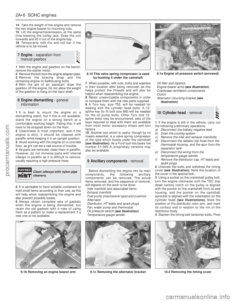
10Another tool which is useful, though by no
means essential, is a valve spring compressor
of the type which hooks under the camshaft
(see illustration). As a Ford tool this bears the
number 21-005-A; proprietary versions may
also be available.
Before dismantling the engine into its main
components, the following ancillary
components can be removed. The actual
items removed, and the sequence of removal,
will depend on the work to be done:
Inlet manifold and associated items
Exhaust manifold
Fuel pump (mechanical type) and pushrod
Alternator
Distributor, HT leads and spark plugs
Fan, water pump and thermostat
Oil pressure switch
(see illustration)
Temperature gauge senderOil filter and dipstick
Engine bearer arms (see illustration)
Crankcase ventilation components
Clutch
Alternator mounting bracket (see
illustration)
1If the engine is still in the vehicle, carry out
the following preliminary operations:
a)Disconnect the battery negative lead
b)Drain the cooling system
c)Remove the inlet and exhaust manifolds
d)Disconnect the radiator top hose from the
thermostat housing, and the spur from the
expansion tank
e)Disconnect the wiring from the
temperature gauge sender
f)Remove the distributor cap, HT leads and
spark plugs
2Unscrew the bolts and withdraw the timing
cover (see illustration). Note the location of
the cover in the special bolt.
3Using a socket on the crankshaft pulley bolt.
turn the engine clockwise until the TDC (top
dead centre) notch on the pulley is aligned
with the pointer on the crankshaft front oil seal
housing, and the pointer on the camshaft
sprocket is aligned with the indentation on the
cylinder head (see illustrations).Note the
position of the distributor rotor arm, and mark
its contact end in relation to the rim of the
distributor body.
4Slacken the timing belt tensioner bolts. Pivot
10Cylinder head - removal
9Ancillary components - removal
8Engine dismantling - general
information
7Engine - separation from
manual gearbox
2A•6SOHCengines
9.1a Engine oil pressure switch (arrowed)
9.1b Removing an engine bearer arm9.1c Removing the alternator bracket
8.10 This valve spring compressor is used
by hooking it under the camshaft
Clean oilways with nylon pipe
cleaners.
10.2 Removing the timing cover
procarmanuals.com
Page 30 of 255
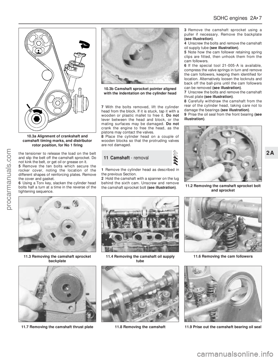
the tensioner to release the load on the belt
and slip the belt off the camshaft sprocket. Do
not kink the belt, or get oil or grease on it.
5Remove the ten bolts which secure the
rocker cover, noting the location of the
different shapes of reinforcing plates. Remove
the cover and gasket.
6Using a Torx key, slacken the cylinder head
bolts half a turn at a time in the reverse of the
tightening sequence.7With the bolts removed, lift the cylinder
head from the block. If it is stuck, tap it with a
wooden or plastic mallet to free it. Do not
lever between the head and block, or the
mating surfaces may be damaged. Do not
crank the engine to free the head, as the
pistons may contact the valves.
8Place the cylinder head on a couple of
wooden blocks so that the protruding valves
are not damaged.
1Remove the cylinder head as described in
the previous Section.
2Hold the camshaft with a spanner on the lug
behind the sixth cam. Unscrew and remove
the camshaft sprocket bolt (see illustration).3Remove the camshaft sprocket using a
puller if necessary. Remove the backplate
(see illustration).
4Unscrew the bolts and remove the camshaft
oil supply tube (see illustration).
5Note how the cam follower retaining spring
clips are fitted, then unhook them from the
cam followers.
6If the special tool 21-005-A is available,
compress the valve springs in turn and remove
the cam followers, keeping them identified for
location. Alternatively loosen the locknuts and
back off the ball-pins until the cam followers
can be removed (see illustration).
7Unscrew the bolts and remove the camshaft
thrust plate (see illustration).
8Carefully withdraw the camshaft from the
rear of the cylinder head, taking care not to
damage the bearings (see illustration).
9Prise the oil seal from the front bearing (see
illustration).11Camshaft - removal
SOHCengines 2A•7
2A
10.3a Alignment of crankshaft and
camshaft timing marks, and distributor
rotor position, for No 1 firing
10.3b Camshaft sprocket pointer aligned
with the indentation on the cylinder head
11.6 Removing the cam followers
11.2 Removing the camshaft sprocket bolt
and sprocket
11.3 Removing the camshaft sprocket
backplate11.4 Removing the camshaft oil supply
tube
11.9 Prise out the camshaft bearing oil seal11.7 Removing the camshaft thrust plate11.8 Removing the camshaft
procarmanuals.com
Page 33 of 255
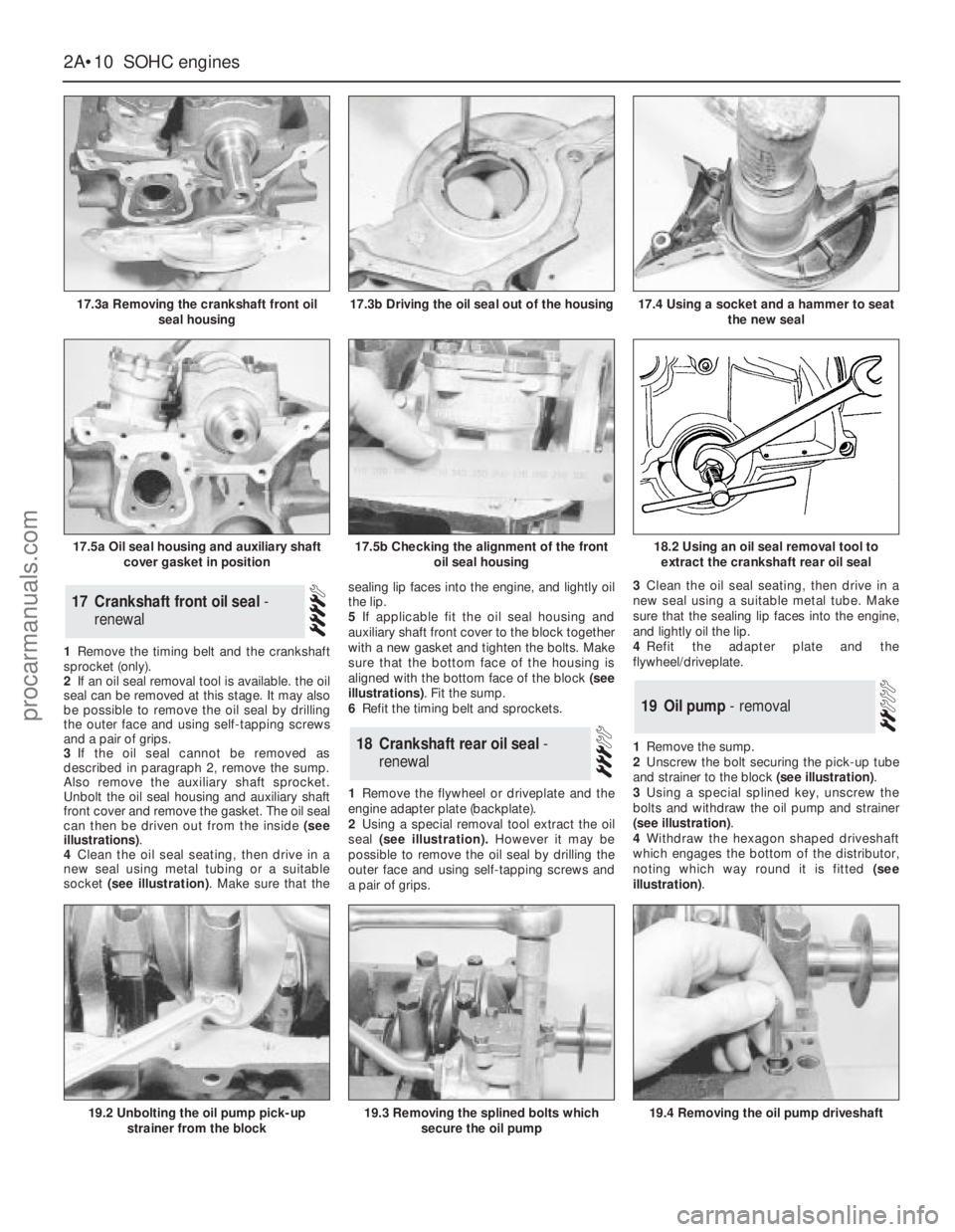
1Remove the timing belt and the crankshaft
sprocket (only).
2If an oil seal removal tool is available. the oil
seal can be removed at this stage. It may also
be possible to remove the oil seal by drilling
the outer face and using self-tapping screws
and a pair of grips.
3If the oil seal cannot be removed as
described in paragraph 2, remove the sump.
Also remove the auxiliary shaft sprocket.
Unbolt the oil seal housing and auxiliary shaft
front cover and remove the gasket. The oil seal
can then be driven out from the inside (see
illustrations).
4Clean the oil seal seating, then drive in a
new seal using metal tubing or a suitable
socket (see illustration). Make sure that thesealing lip faces into the engine, and lightly oil
the lip.
5If applicable fit the oil seal housing and
auxiliary shaft front cover to the block together
with a new gasket and tighten the bolts. Make
sure that the bottom face of the housing is
aligned with the bottom face of the block (see
illustrations). Fit the sump.
6Refit the timing belt and sprockets.
1Remove the flywheel or driveplate and the
engine adapter plate (backplate).
2Using a special removal tool extract the oil
seal (see illustration).However it may be
possible to remove the oil seal by drilling the
outer face and using self-tapping screws and
a pair of grips.3Clean the oil seal seating, then drive in a
new seal using a suitable metal tube. Make
sure that the sealing lip faces into the engine,
and lightly oil the lip.
4Refit the adapter plate and the
flywheel/driveplate.
1Remove the sump.
2Unscrew the bolt securing the pick-up tube
and strainer to the block (see illustration).
3Using a special splined key, unscrew the
bolts and withdraw the oil pump and strainer
(see illustration).
4Withdraw the hexagon shaped driveshaft
which engages the bottom of the distributor,
noting which way round it is fitted (see
illustration).
19Oil pump - removal
18Crankshaft rear oil seal -
renewal
17Crankshaft front oil seal -
renewal
2A•10SOHCengines
17.3a Removing the crankshaft front oil
seal housing
19.2 Unbolting the oil pump pick-up
strainer from the block19.3 Removing the splined bolts which
secure the oil pump19.4 Removing the oil pump driveshaft
18.2 Using an oil seal removal tool to
extract the crankshaft rear oil seal
17.3b Driving the oil seal out of the housing
17.5a Oil seal housing and auxiliary shaft
cover gasket in position17.5b Checking the alignment of the front
oil seal housing
17.4 Using a socket and a hammer to seat
the new seal
procarmanuals.com
Page 39 of 255
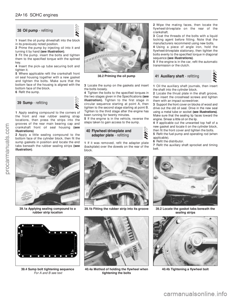
1Insert the oil pump driveshaft into the block
in its previously noted position.
2Prime the pump by injecting oil into it and
turning it by hand (see illustration).
3Fit the pump. insert the bolts and tighten
them to the specified torque with the splined
key.
4Insert the pick-up tube securing bolt and
tighten it.
5Where applicable refit the crankshaft front
oil seal housing together with a new gasket
and tighten the bolts. Make sure that the
bottom face of the housing is aligned with the
bottom face of the block.
6Refit the sump.
1Apply sealing compound to the corners of
the front and rear rubber sealing strap
locations, then press the strips into the
grooves of the rear main bearing cap and
crankshaft front oil seal housing (see
illustrations)
2Apply a little sealing compound to the
bottom face of the cylinder block, then fit the
sump gaskets in position and locate the end
tabs beneath the rubber sealing strips (see
illustration).3Locate the sump on the gaskets and insert
the bolts loosely.
4Tighten the bolts to the specified torques in
the two stages given in the Specifications(see
illustration).Tighten to the first stage in
circular sequence starting at point A, then
tighten to the second stage starting at point B.
Tighten to the third stage after the engine has
been running for twenty minutes.
5If the engine is in the vehicle, reverse the
steps taken to gain access to the sump.
1If it was removed, refit the adapter plate
(backplate) over the dowels on the rear of the
block.2Wipe the mating faces, then locate the
flywheel/driveplate on the rear of the
crankshaft.
3Coat the threads of the bolts with a liquid
locking agent before fitting. Note that the
manufacturers recommend using new bolts.
4Using a piece of angle iron, hold the
flywheel/driveplate stationary, then tighten the
bolts evenly to the specified torque in diagonal
sequence (see illustrations).
5If the engine is in the car, refit the automatic
transmission or the clutch.
1Oil the auxiliary shaft journals, then insert
the shaft into the cylinder block.
2Locate the thrust plate in the shaft groove,
then insert the crosshead screws and tighten
them with an impact screwdriver.
3Support the front cover on blocks of wood and
drive out the old oil seal. Drive in the new seal
using a metal tube or socket (see illustrations).
Make sure that the sealing lip faces toward the
engine. Smear a little oil on the lip.
4If applicable cut the unwanted top half of a
new gasket and locate it on the cylinder block,
then fit the front cover and tighten the bolts.
5Refit the fuel pump and operating rod (when
applicable).
6Refit the distributor.
7Refit the auxiliary shaft sprocket and timing
belt.
41Auxiliary shaft - refitting
40Flywheel/driveplate and
adapter plate - refitting
39Sump - refitting
38Oil pump - refitting
2A•16SOHCengines
38.2 Priming the oil pump
40.4a Method of holding the flywheel when
tightening the bolts39.4 Sump bolt tightening sequence
For A and B see text40.4b Tightening a flywheel bolt
39.2 Locate the gasket tabs beneath the
sealing strips39.1a Applying sealing compound to a
rubber strip location39.1b Fitting the rubber strip into its groove
procarmanuals.com
Page 40 of 255
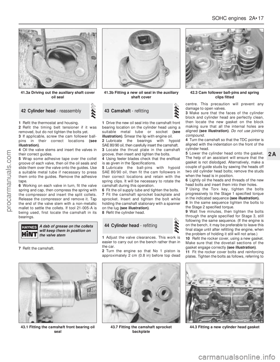
1Refit the thermostat and housing.
2Refit the timing belt tensioner if it was
removed, but do not tighten the bolts yet.
3If applicable, screw the cam follower ball-
pins in their correct locations (see
illustration).
4Oil the valve stems and insert the valves in
their correct guides.
5Wrap some adhesive tape over the collet
groove of each valve, then oil the oil seals and
slide them over the valve onto the guides. Use
a suitable metal tube if necessary to press
them onto the guides. Remove the adhesive
tape.
6Working on each valve in turn, fit the valve
spring and cap, then compress the spring with
the compressor and insert the split collets.
Release the compressor and remove it. Tap
the end of the valve stem with a non-metallic
mallet to settle the collets. If tool 21-005-A is
being used, first locate the camshaft in its
bearings.
7Refit the camshaft.1Drive the new oil seal into the camshaft front
bearing location on the cylinder head using a
suitable metal tube or socket (see
illustration). Smear the lip with engine oil.
2Lubricate the bearings with hypoid
SAE 80/90 oil, then carefully insert the camshaft.
3Locate the thrust plate in the camshaft
groove, then insert and tighten the bolts.
4Using feeler blades check that the endfloat
is as given in the Specifications.
5Lubricate the ball-pins with hypoid
SAE 80/90 oil, then fit the cam followers in
their correct locations and retain with the
spring clips. It will be necessary to rotate the
camshaft during this operation.
6Fit the oil supply tube and tighten the bolts.
7Fit the camshaft sprocket backplate and
sprocket. Insert and tighten the bolt while
holding the camshaft stationary with a spanner
on the lug (see illustration).
8Refit the cylinder head.
1Adjust the valve clearances. This work is
easier to carry out on the bench rather than in
the car.
2Turn the engine so that No 1 piston is
approximately 2 cm (0.8 in) before top deadcentre. This precaution will prevent any
damage to open valves.
3Make sure that the faces of the cylinder
block and cylinder head are perfectly clean,
then locate the new gasket on the block
making sure that all the internal holes are
aligned (see illustration). Do not use jointing
compound.
4Turn the camshaft so that the TDC pointer is
aligned with the indentation on the front of the
cylinder head.
5Lower the cylinder head onto the gasket.
The help of an assistant will ensure that the
gasket is not dislodged. Alternatively, make a
couple of guide studs by sawing the heads off
two old cylinder head bolts; remove the studs
when the head is in position.
6Lightly oil the heads and threads of the new
head bolts and insert them into their holes.
7Using the Torx key, tighten the bolts
progressively to the Stage 1 specified torque
in the indicated sequence(see illustration).
8In the same sequence tighten the bolts to
the Stage 2 specified torque.
9Wait five minutes, then tighten the bolts
through the angle specified for Stage 3, still
following the same sequence. (If the engine is
on the bench, it may be preferable to leave this
final stage until after refitting the engine, when
the problem of holding it still will not arise.)
10Refit the rocker cover, using a new gasket.
Make sure that the dovetail sections of the
gasket engage correctly (see illustration).
11Fit the rocker cover bolts and reinforcing
plates. Tighten the bolts as follows, referring to
44Cylinder head - refitting
43Camshaft - refitting42Cylinder head - reassembly
SOHCengines 2A•17
2A
41.3a Driving out the auxiliary shaft cover
oil seal41.3b Fitting a new oil seal in the auxiliary
shaft cover42.3 Cam follower ball-pins and spring
clips fitted
43.1 Fitting the camshaft front bearing oil
seal43.7 Fitting the camshaft sprocket
backplate44.3 Fitting a new cylinder head gasket
A dab of grease on the collets
will keep them in position on
the valve stem
procarmanuals.com