1985 FORD GRANADA key
[x] Cancel search: keyPage 80 of 255
29Fit the sump and the retaining nuts and
bolts. Tighten them progressively in two stages.
30Oil the lip of the timing cover oil seal and
the contact surface of the crankshaft damper.
31Fit the damper to the crankshaft, being
careful not to dislodge the Woodruff key. Draw
the damper into position using the retaining
bolt and washer.
32Remove the bolt and apply sealant to the
faces of the washer. Refit the bolt and washer
then jam the starter gear ring teeth and tighten
the bolt to the specified torque.
33Refit the crankshaft pulley and tighten the
retaining bolts to the specified torque.
34Refit the crossmember side brackets and
brake pipes.
35Reconnect the engine mountings and
remove the engine hoist or axle stands (see
“Jacking”).36Connect the steering shaft coupling with
the steering wheel and front roadwheels in the
straight-ahead position. Fit the pinch-bolt and
tighten it to the specified torque.
37Fit the starter motor and connect the leads.
38Bolt the coolant distributor pipe to the
timing cover.
39Refit the alternator and power steering
pump drivebelts and tension them (see
illustrations).
40Fit the fan and radiator, connect all coolant
hoses, and fit the radiator upper shroud.
41Fit the air cleaner cover with attachments.
42Fill the engine with oil and coolant and
connect the battery.
2.8 litre engine
1Clean the mating faces of the crankcase
and sump. Ensure that the grooves in the seal
carriers are clean.
2Fit the rubber seals in the grooves.
3Apply sealing compound on the crankcase
and slide the tabs of the gasket under the cut-
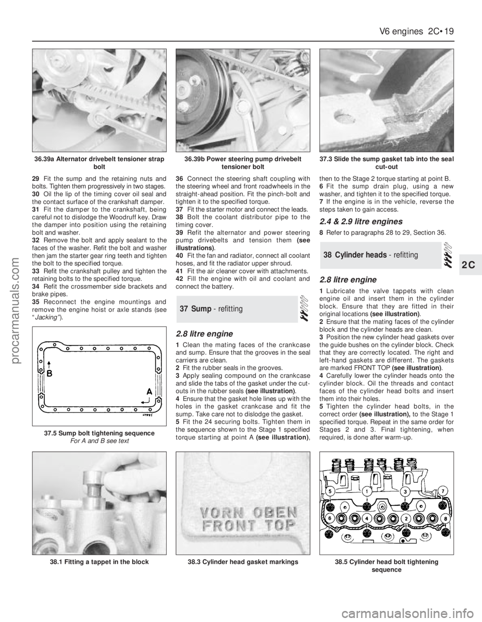
outs in the rubber seals (see illustration).
4Ensure that the gasket hole lines up with the
holes in the gasket crankcase and fit the
sump. Take care not to dislodge the gasket.
5Fit the 24 securing bolts. Tighten them in
the sequence shown to the Stage 1 specified
torque starting at point A (see illustration),then to the Stage 2 torque starting at point B.
6Fit the sump drain plug, using a new
washer, and tighten it to the specified torque.
7If the engine is in the vehicle, reverse the
steps taken to gain access.
2.4 & 2.9 litre engines
8Refer to paragraphs 28 to 29, Section 36.
2.8 litre engine
1Lubricate the valve tappets with clean
engine oil and insert them in the cylinder
block. Ensure that they are fitted in their
original locations (see illustration).
2Ensure that the mating faces of the cylinder
block and the cylinder heads are clean.
3Position the new cylinder head gaskets over
the guide bushes on the cylinder block. Check
that they are correctly located. The right and
left-hand gaskets are different. The gaskets
are marked FRONT TOP (see illustration).
4Carefully lower the cylinder heads onto the
cylinder block. Oil the threads and contact
faces of the cylinder head bolts and insert
them into their holes.
5Tighten the cylinder head bolts, in the
correct order(see illustration),to the Stage 1
specified torque. Repeat in the same order for
Stages 2 and 3. Final tightening, when
required, is done after warm-up.
38Cylinder heads - refitting
37Sump - refitting
V6 engines 2C•19
2C
36.39a Alternator drivebelt tensioner strap
bolt36.39b Power steering pump drivebelt
tensioner bolt37.3 Slide the sump gasket tab into the seal
cut-out
38.1 Fitting a tappet in the block
37.5 Sump bolt tightening sequence
For A and B see text
38.3 Cylinder head gasket markings38.5 Cylinder head bolt tightening
sequence
procarmanuals.com
Page 99 of 255
25To remove the pump, first remove the fuel
tank.
26Unscrew the fuel pump/fuel level sender
unit by engaging two crossed screwdrivers in
the slots on either side of the unit mounting
flange. Recover the seal.
27Refitting is a reversal of removal. It is
necessary to fit a new seal.
1Run the fuel level as low as possible before
removing the tank.
2Disconnect the battery negative lead.
3Remove the fuel filler cap. Siphon or pump
the remaining fuel out of the tank. Store the
fuel in a suitable sealed container.
4Remove the two screws on either side of the
filler neck.
5Raise and support the rear of the vehicle.
6Remove the shield from the right-hand rear
inner wheel arch. Also remove the rear bumper
undershield. which is secured by six screws.
7Disconnect the fuel supply and return lines
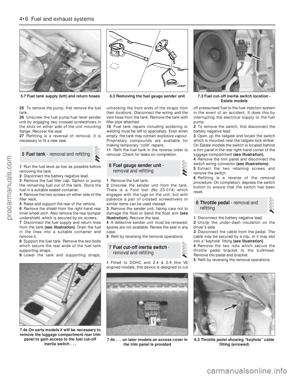
from the tank (see illustration). Drain the fuel
in the lines into a suitable container and
remove it.
8Support the fuel tank. Remove the two bolts
which secure the rear ends of the fuel tank
supporting straps.
9Lower the tank and supporting straps,unhooking the front ends of the straps from
their locations. Disconnect the wiring and the
vent hose from the tank. Remove the tank with
filler pipe attached.
10Fuel tank repairs including soldering or
welding must be left to specialists. Even when
empty, the tank may contain explosive vapour.
Proprietary compounds are available for
making temporary “cold” repairs.
11Refit the fuel tank in the reverse order to
removal. Check for leaks on completion.
1Remove the fuel tank.
2Unscrew the sender unit from the tank.
There is a Ford tool (No 23-014) which
engages with the lugs on the unit, but with
patience a pair of crossed screwdrivers or
similar items can be used instead.
3Remove the sender unit, taking care not to
damage the float or bend the float arm(see
illustration).Recover the seal.
4A defective sender unit must be renewed;
spares are not available. Renew the seal in any
case.
5Refit by reversing the removal operations.
1Fitted to DOHC and 2.4 & 2.9 litre V6
engined models, this device is designed to cutoff pressurised fuel to the fuel-injection system
in the event of an accident. It does this by
interrupting the electrical supply to the fuel
pump.
2To remove the switch, first disconnect the
battery negative lead.
3Open up the tailgate and locate the switch
which is mounted near the tailgate lock striker.
On Estate models the switch is located behind
a trim panel in the rear right-hand corner of the
luggage compartment (see illustration).
4Remove the trim panel and disconnect the
switch wiring connector (see illustrations).
5Extract the two retaining screws and
remove the switch.
6Refitting is a reverse of the removal
procedure. On completion, depress the switch
button to ensure that the switch has been
reset.
1Disconnect the battery negative lead.
2Unclip the under-dash insulation on the
driver’s side.
3Disconnect the cable from the pedal. The
cable may be secured by a clip, or it may slot
into a “keyhole” fitting (see illustration).
4Remove the two nuts which secure the
throttle pedal bracket to the bulkhead.
Remove the pedal and bracket.
5Refit by reversing the removal operations.
8Throttle pedal - removal and
refitting
7Fuel cut-off inertia switch -
removal and refitting
6Fuel gauge sender unit -
removal and refitting
5Fuel tank - removal and refitting
4•6Fuel and exhaust systems
5.7 Fuel tank supply (left) and return hoses
7.4a On early models it will be necessary to
remove the luggage compartment rear trim
panel to gain access to the fuel cut-off
inertia switch . . .
7.4b . . . on later models an access cover in
the trim panel is provided8.3 Throttle pedal showing “keyhole” cable
fitting (arrowed)
6.3 Removing the fuel gauge sender unit7.3 Fuel cut-off inertia switch location -
Estate models
procarmanuals.com
Page 102 of 255
1Check the cost and availability of spare parts
before deciding to dismantle the carburettor. If
the unit has seen much service, fitting a new or
reconditioned carburettor may prove more
satisfactory than any attempt at overhaul.
2Obtain a carburettor repair kit, which will
contain the necessary gaskets, diaphragms
and other renewable items.
3With the carburettor removed from the
vehicle, clean it thoroughly externally and
place it on a clean worksurface.
4 Referringto the exploded view of the
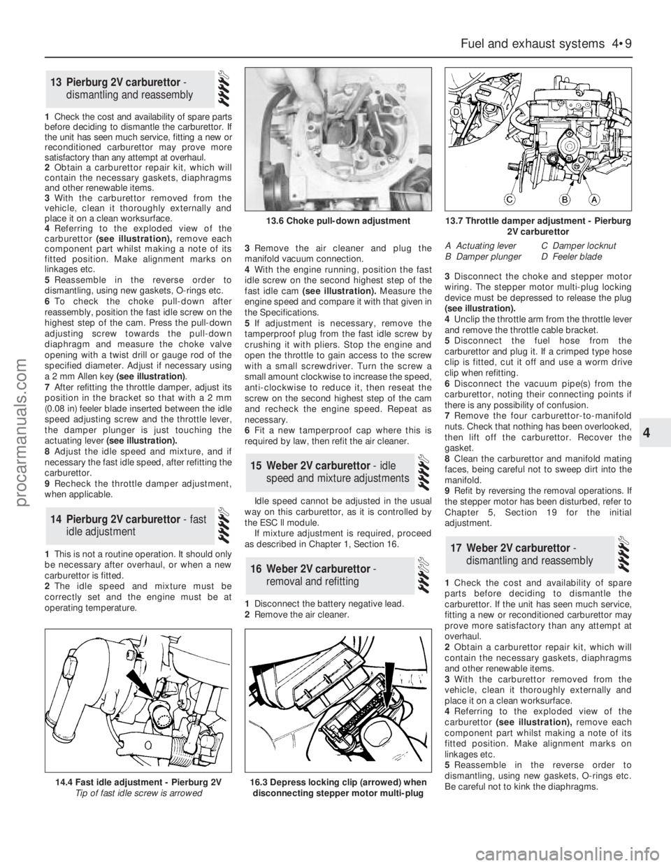
carburettor(see illustration),remove each
component part whilst making a note of its
fitted position. Make alignment marks on
linkages etc.
5Reassemble in the reverse order to
dismantling, using new gaskets, O-rings etc.
6To check the choke pull-down after
reassembly, position the fast idle screw on the
highest step of the cam. Press the pull-down
adjusting screw towards the pull-down
diaphragm and measure the choke valve
opening with a twist drill or gauge rod of the
specified diameter. Adjust if necessary using
a 2 mm Allen key (see illustration).
7After refitting the throttle damper, adjust its
position in the bracket so that with a 2 mm
(0.08 in) feeler blade inserted between the idle
speed adjusting screw and the throttle lever,
the damper plunger is just touching the
actuating lever(see illustration).
8Adjust the idle speed and mixture, and if
necessary the fast idle speed, after refitting the
carburettor.
9Recheck the throttle damper adjustment,
when applicable.
1This is not a routine operation. It should only
be necessary after overhaul, or when a new
carburettor is fitted.
2The idle speed and mixture must be
correctly set and the engine must be at
operating temperature.3Remove the air cleaner and plug the
manifold vacuum connection.
4With the engine running, position the fast
idle screw on the second highest step of the
fast idle cam(see illustration).Measure the
engine speed and compare it with that given in
the Specifications.
5If adjustment is necessary, remove the
tamperproof plug from the fast idle screw by
crushing it with pliers. Stop the engine and
open the throttle to gain access to the screw
with a small screwdriver. Turn the screw a
small amount clockwise to increase the speed,
anti-clockwise to reduce it, then reseat the
screw on the second highest step of the cam
and recheck the engine speed. Repeat as
necessary.
6Fit a new tamperproof cap where this is
required by law, then refit the air cleaner.
Idle speed cannot be adjusted in the usual
way on this carburettor, as it is controlled by
the ESC ll module.
If mixture adjustment is required, proceed
as described in Chapter 1, Section 16.
1Disconnect the battery negative lead.
2Remove the air cleaner.3Disconnect the choke and stepper motor
wiring. The stepper motor multi-plug locking
device must be depressed to release the plug
(seeillustration).
4Unclip the throttle arm from the throttle lever
and remove the throttle cable bracket.
5Disconnect the fuel hose from the
carburettor and plug it. If a crimped type hose
clip is fitted, cut it off and use a worm drive
clip when refitting.
6Disconnect the vacuum pipe(s) from the
carburettor, noting their connecting points if
there is any possibility of confusion.
7Remove the four carburettor-to-manifold
nuts. Check that nothing has been overlooked,
then lift off the carburettor. Recover the
gasket.
8Clean the carburettor and manifold mating
faces, being careful not to sweep dirt into the
manifold.
9Refit by reversing the removal operations. If
the stepper motor has been disturbed, refer to
Chapter 5, Section 19 for the initial
adjustment.
1Check the cost and availability of spare
parts before deciding to dismantle the
carburettor. If the unit has seen much service,
fitting a new or reconditioned carburettor may
prove more satisfactory than any attempt at
overhaul.
2Obtain a carburettor repair kit, which will
contain the necessary gaskets, diaphragms
and other renewable items.
3With the carburettor removed from the
vehicle, clean it thoroughly externally and
place it on a clean worksurface.
4 Referringto the exploded view of the
carburettor(see illustration),remove each
component part whilst making a note of its
fitted position. Make alignment marks on
linkages etc.
5Reassemble in the reverse order to
dismantling, using new gaskets, O-rings etc.
Be careful not to kink the diaphragms.
17Weber 2V carburettor -
dismantling and reassembly
16Weber 2V carburettor -
removal and refitting
15Weber 2V carburettor - idle
speed and mixture adjustments
14Pierburg 2V carburettor - fast
idle adjustment
13Pierburg 2V carburettor -
dismantling and reassembly
Fuel and exhaust systems 4•9
4
14.4 Fast idle adjustment - Pierburg 2V
Tip of fast idle screw is arrowed
13.6 Choke pull-down adjustment13.7 Throttle damper adjustment - Pierburg
2V carburettor
A Actuating lever
B Damper plungerC Damper locknut
D Feeler blade
16.3 Depress locking clip (arrowed) when
disconnecting stepper motor multi-plug
procarmanuals.com
Page 107 of 255
16Start the engine and note the engine
speed (rpm). The engine speed should
increase above the normal idle speed, and
should be as given in the Specifications.
17If the engine speed is not as specified,
remove the tamperproof plug from the top of
the throttle kicker housing, and turn the
adjustment screw to give the specified speed.
18On completion of adjustment, fit a new
tamperproof cap.
19Disconnect the tubing from the inlet
manifold, and reconnect the throttle kicker
vacuum hose.
20Refit the plastic shield and the air cleaner.
On 2.4 & 2.9 litre V6 models especially,
residual pressure will remain in the fuel lines
long after the vehicle was last used therefore
the fuel system must be depressurised before
any hose is disconnected; the system is
depressurised via the vent valve on the fuel
rail, noting that it may be necessary to depress
the valve several times before the pressure is
fully released. As an added precaution place a
rag over the valve as it is depressed to catch
any fuel which is forcibly expelled. Before
carrying out any operation on the fuel system
refer to the precautions given in Safety first! at
the beginning of this Manual and follow them
implicitly. Petrol is a highly dangerous and
volatile liquid and the precautions necessary
when handling it cannot be overstressed.
Access to the relays is obtained by
removing the facia top cover (crash pad).
The relays are located on the passenger
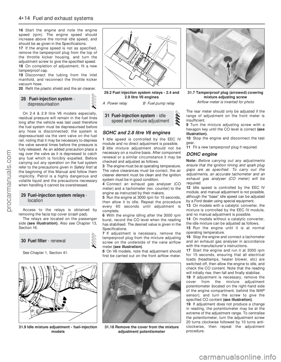
side(see illustration). Also see Chapter 13,
Section 16.
See Chapter 1, Section 41.
SOHC and 2.8 litre V6 engines
1Idle speed is controlled by the EEC IV
module and no direct adjustment is possible.
2Idle mixture adjustment should not be
necessary on a routine basis. After component
renewal or a similar circumstance it may be
checked and adjusted as follows.
3The engine must be at operating temperature.
The valve clearances must be correct, the air
cleaner element must be clean and the ignition
system must be in good condition.
4Connect an exhaust gas analyser (CO
meter) and a tachometer (rev. counter) to the
engine as instructed by their makers.
5Run the engine at 3000 rpm for 15 seconds,
then allow it to idle. Repeat the procedure
every 60 seconds until adjustment is
complete.
6With the engine idling after the 3000 rpm
burst, record the CO level when the reading
has stabilised. The desired value is given in the
Specifications.
7If adjustment is necessary, remove the
tamperproof plug from the mixture adjusting
screw on the underside of the vane airflow
meter (see illustration).
8On V6 models, note that adjustment should
first be carried out on the front airflow meter.The rear meter should only be adjusted if the
range of adjustment on the front meter is
insufficient.
9Turn the mixture adjusting screw with a
hexagon key until the CO level is correct (see
illustration).
10Stop the engine and disconnect the test
gear.
11Fit a new tamperproof plug if required.
DOHC engine
Note: Before carrying out any adjustments
ensure that the ignition timing and spark plug
gaps are as specified. To carry out the
adjustments, an accurate tachometer and an
exhaust gas analyser (CO meter) will be
required.
12Idle speed is controlled by the EEC IV
module, and manual adjustment is not possible,
although the “base” idle speed can be adjusted
by a Ford dealer using special equipment.
13On models with a catalytic converter, the
mixture is controlled by the EEC IV module,
and no manual adjustment is possible.
14On models without a catalytic converter,
the idle mixture can be adjusted as follows.
15Run the engine until it is at normal
operating temperature.
16Stop the engine and connect a tachometer
and an exhaust gas analyser in accordance
with the manufacturer’s instructions.
17Start the engine and run it at 3000 rpm
for 15 seconds, ensuring that all electrical
loads (headlamps, heater blower, etc) are
switched off, then allow the engine to idle, and
check the CO content. Note that the reading
will initially rise, then fall and finally stabilise.
18If adjustment is necessary, remove the
cover from the mixture adjustment
potentiometer (located on the right-hand side
of the engine compartment, behind the MAP
sensor), and turn the screw to give the
specified CO content (see illustration).
19If adjustment does not produce a change
in reading, the potentiometer may be at the
extreme of the adjustment range. To centralise
the potentiometer, turn the adjustment screw
20 turns clockwise followed by 10 turns anti-
clockwise, then repeat the adjustment
procedure.
31Fuel-injection system - idle
speed and mixture adjustment
30Fuel filter - renewal
29Fuel-injection system relays -
location
28Fuel-injection system -
depressurisation
4•14Fuel and exhaust systems
31.18 Remove the cover from the mixture
adjustment potentiometer31.9 Idle mixture adjustment - fuel-injection
models
29.2 Fuel injection system relays - 2.4 and
2.9 litre V6 engines
A Power relayB Fuel pump relay
31.7 Tamperproof plug (arrowed) covering
mixture adjusting screw
Airflow meter is inverted for photo
procarmanuals.com
Page 133 of 255
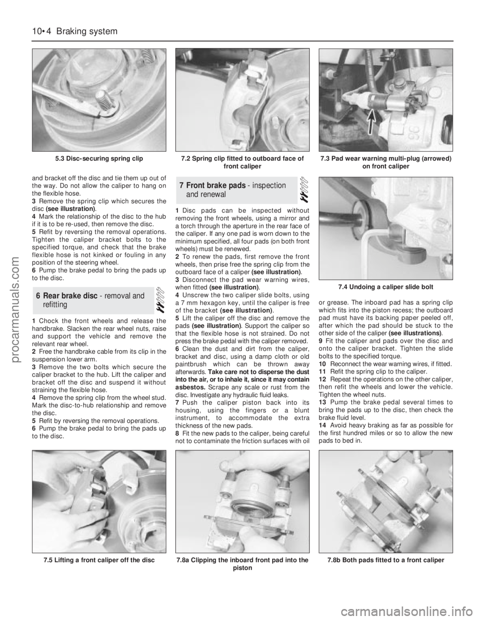
and bracket off the disc and tie them up out of
the way. Do not allow the caliper to hang on
the flexible hose.
3Remove the spring clip which secures the
disc (see illustration).
4Mark the relationship of the disc to the hub
if it is to be re-used, then remove the disc.
5Refit by reversing the removal operations.
Tighten the caliper bracket bolts to the
specified torque, and check that the brake
flexible hose is not kinked or fouling in any
position of the steering wheel.
6Pump the brake pedal to bring the pads up
to the disc.
1Chock the front wheels and release the
handbrake. Slacken the rear wheel nuts, raise
and support the vehicle and remove the
relevant rear wheel.
2Free the handbrake cable from its clip in the
suspension lower arm.
3Remove the two bolts which secure the
caliper bracket to the hub. Lift the caliper and
bracket off the disc and suspend it without
straining the flexible hose.
4Remove the spring clip from the wheel stud.
Mark the disc-to-hub relationship and remove
the disc.
5Refit by reversing the removal operations.
6Pump the brake pedal to bring the pads up
to the disc.1Disc pads can be inspected without
removing the front wheels, using a mirror and
a torch through the aperture in the rear face of
the caliper. If any one pad is worn down to the
minimum specified, all four pads (on both front
wheels) must be renewed.
2To renew the pads, first remove the front
wheels, then prise free the spring clip from the
outboard face of a caliper (see illustration).
3Disconnect the pad wear warning wires,
when fitted (see illustration).
4Unscrew the two caliper slide bolts, using
a 7 mm hexagon key, until the caliper is free
of the bracket (see illustration).
5Lift the caliper off the disc and remove the
pads (see illustration). Support the caliper so
that the flexible hose is not strained. Do not
press the brake pedal with the caliper removed.
6Clean the dust and dirt from the caliper,
bracket and disc, using a damp cloth or old
paintbrush which can be thrown away
afterwards. Take care not to disperse the dust
into the air, or to inhale it, since it may contain
asbestos. Scrape any scale or rust from the
disc. Investigate any hydraulic fluid leaks.
7Push the caliper piston back into its
housing, using the fingers or a blunt
instrument, to accommodate the extra
thickness of the new pads.
8Fit the new pads to the caliper, being careful
not to contaminate the friction surfaces with oilor grease. The inboard pad has a spring clip
which fits into the piston recess; the outboard
pad must have its backing paper peeled off,
after which the pad should be stuck to the
other side of the caliper (see illustrations).
9Fit the caliper and pads over the disc and
onto the caliper bracket. Tighten the slide
bolts to the specified torque.
10Reconnect the wear warning wires, if fitted.
11Refit the spring clip to the caliper.
12Repeat the operations on the other caliper,
then refit the wheels and lower the vehicle.
Tighten the wheel nuts.
13Pump the brake pedal several times to
bring the pads up to the disc, then check the
brake fluid level.
14Avoid heavy braking as far as possible for
the first hundred miles or so to allow the new
pads to bed in.7Front brake pads - inspection
and renewal
6Rear brake disc - removal and
refitting
10•4Braking system
5.3 Disc-securing spring clip
7.5 Lifting a front caliper off the disc7.8a Clipping the inboard front pad into the
piston
7.4 Undoing a caliper slide bolt
7.8b Both pads fitted to a front caliper
7.2 Spring clip fitted to outboard face of
front caliper7.3 Pad wear warning multi-plug (arrowed)
on front caliper
procarmanuals.com
Page 136 of 255
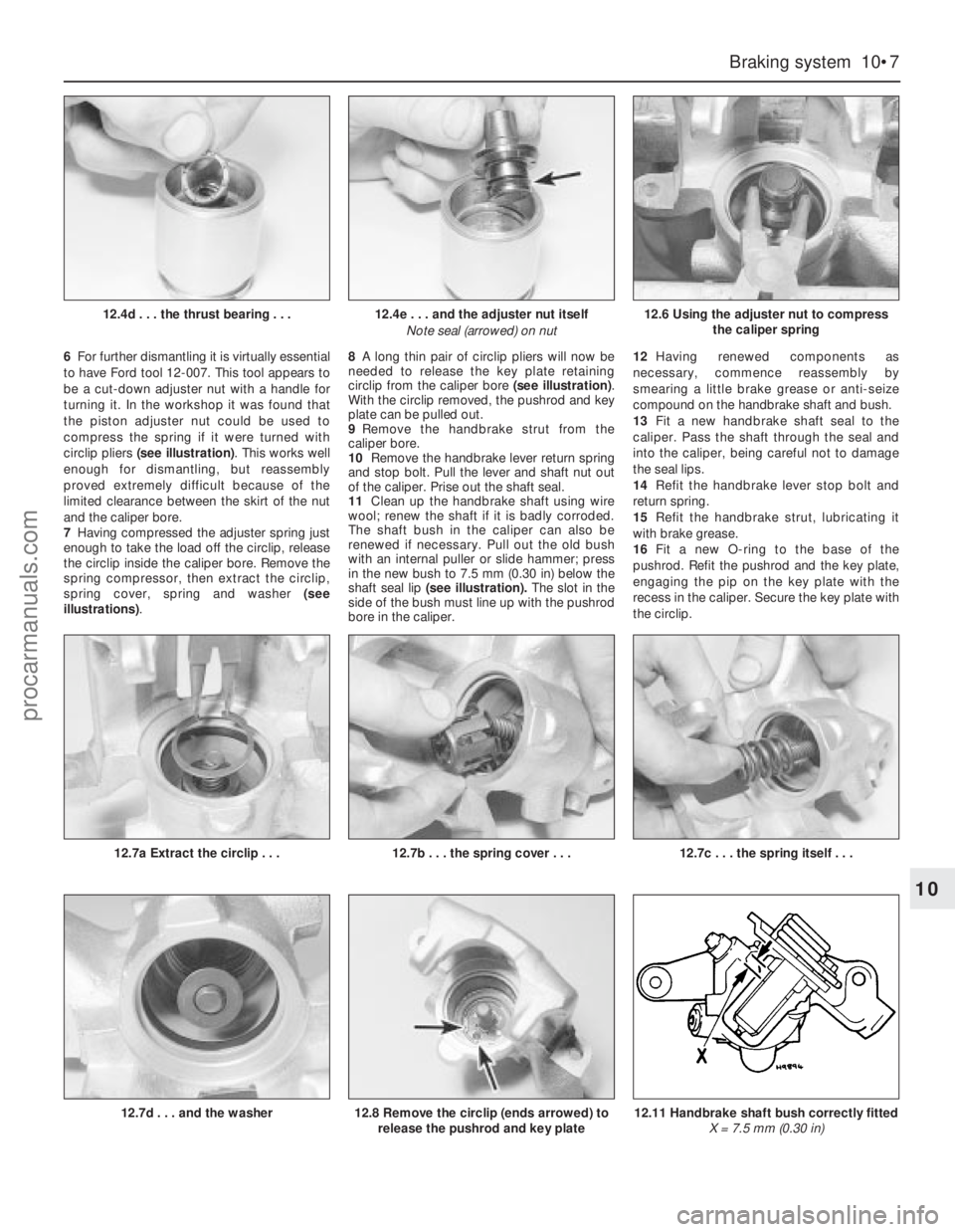
6For further dismantling it is virtually essential
to have Ford tool 12-007. This tool appears to
be a cut-down adjuster nut with a handle for
turning it. In the workshop it was found that
the piston adjuster nut could be used to
compress the spring if it were turned with
circlip pliers (see illustration). This works well
enough for dismantling, but reassembly
proved extremely difficult because of the
limited clearance between the skirt of the nut
and the caliper bore.
7Having compressed the adjuster spring just
enough to take the load off the circlip, release
the circlip inside the caliper bore. Remove the
spring compressor, then extract the circlip,
spring cover, spring and washer (see
illustrations). 8A long thin pair of circlip pliers will now be
needed to release the key plate retaining
circlip from the caliper bore (see illustration).
With the circlip removed, the pushrod and key
plate can be pulled out.
9Remove the handbrake strut from the
caliper bore.
10Remove the handbrake lever return spring
and stop bolt. Pull the lever and shaft nut out
of the caliper. Prise out the shaft seal.
11Clean up the handbrake shaft using wire
wool; renew the shaft if it is badly corroded.
The shaft bush in the caliper can also be
renewed if necessary. Pull out the old bush
with an internal puller or slide hammer; press
in the new bush to 7.5 mm (0.30 in) below the
shaft seal lip(seeillustration).The slot in the
side of the bush must line up with the pushrod
bore in the caliper.12Having renewed components as
necessary, commence reassembly by
smearing a little brake grease or anti-seize
compound on the handbrake shaft and bush.
13Fit a new handbrake shaft seal to the
caliper. Pass the shaft through the seal and
into the caliper, being careful not to damage
the seal lips.
14Refit the handbrake lever stop bolt and
return spring.
15Refit the handbrake strut, lubricating it
with brake grease.
16Fit a new O-ring to the base of the
pushrod. Refit the pushrod and the key plate,
engaging the pip on the key plate with the
recess in the caliper. Secure the key plate with
the circlip.
Braking system 10•7
10
12.4e . . . and the adjuster nut itself
Note seal (arrowed) on nut
12.7c . . . the spring itself . . .
12.6 Using the adjuster nut to compress
the caliper spring
12.7a Extract the circlip . . .12.7b . . . the spring cover . . .
12.7d . . . and the washer12.11 Handbrake shaft bush correctly fitted
X = 7.5 mm (0.30 in)12.8 Remove the circlip (ends arrowed) to
release the pushrod and key plate
12.4d . . . the thrust bearing . . .
procarmanuals.com
Page 138 of 255
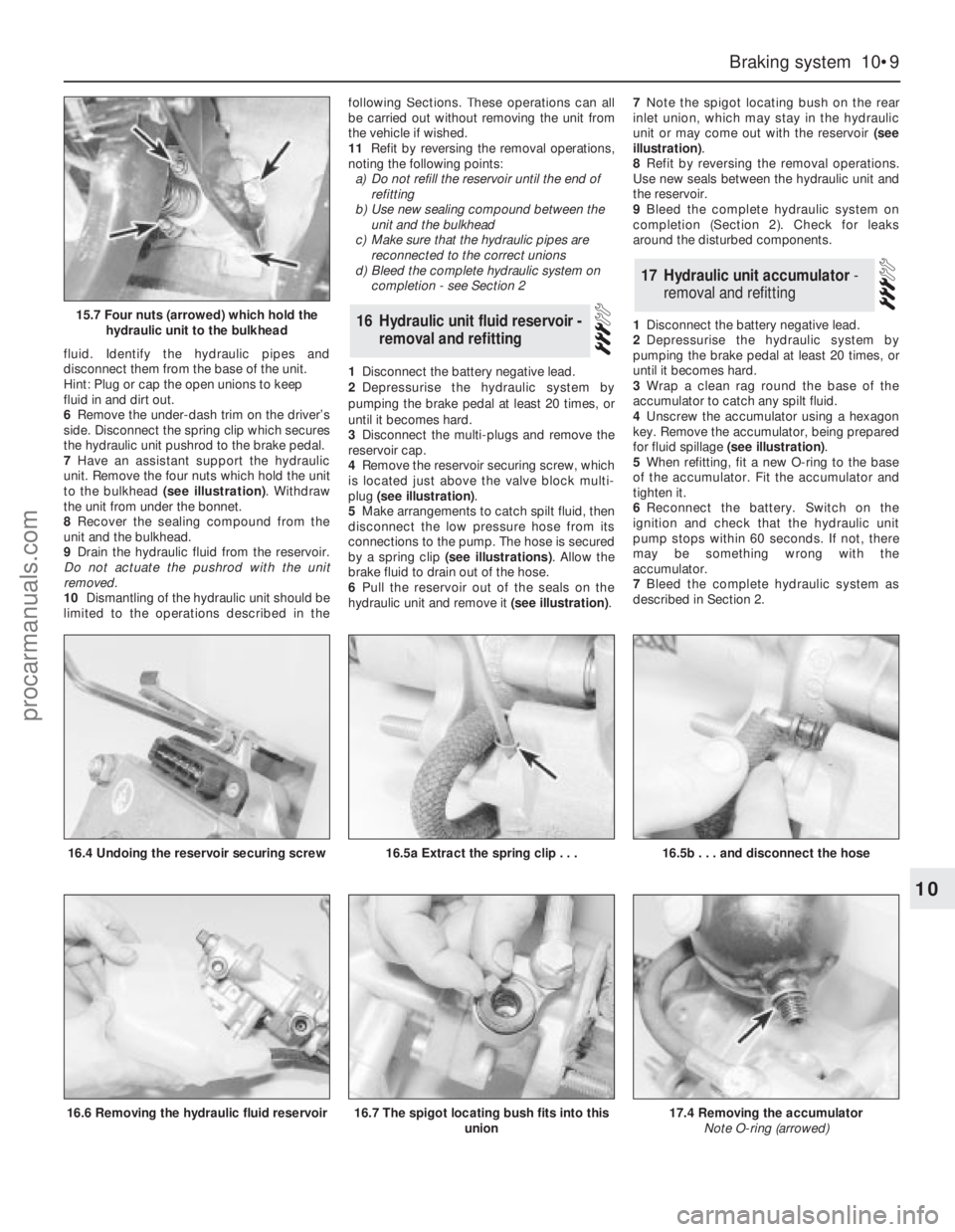
fluid. Identify the hydraulic pipes and
disconnect them from the base of the unit.
Hint: Plug or cap the open unions to keep
fluid in and dirt out.
6Remove the under-dash trim on the driver’s
side. Disconnect the spring clip which secures
the hydraulic unit pushrod to the brake pedal.
7Have an assistant support the hydraulic
unit. Remove the four nuts which hold the unit
to the bulkhead (see illustration). Withdraw
the unit from under the bonnet.
8Recover the sealing compound from the
unit and the bulkhead.
9Drain the hydraulic fluid from the reservoir.
Do not actuate the pushrod with the unit
removed.
10Dismantling of the hydraulic unit should be
limited to the operations described in thefollowing Sections. These operations can all
be carried out without removing the unit from
the vehicle if wished.
11Refit by reversing the removal operations,
noting the following points:
a)Do not refill the reservoir until the end of
refitting
b)Use new sealing compound between the
unit and the bulkhead
c)Make sure that the hydraulic pipes are
reconnected to the correct unions
d)Bleed the complete hydraulic system on
completion - see Section 2
1Disconnect the battery negative lead.
2Depressurise the hydraulic system by
pumping the brake pedal at least 20 times, or
until it becomes hard.
3Disconnect the multi-plugs and remove the
reservoir cap.
4Remove the reservoir securing screw, which
is located just above the valve block multi-
plug (see illustration).
5Make arrangements to catch spilt fluid, then
disconnect the low pressure hose from its
connections to the pump. The hose is secured
by a spring clip (see illustrations). Allow the
brake fluid to drain out of the hose.
6Pull the reservoir out of the seals on the
hydraulic unit and remove it (see illustration).7Note the spigot locating bush on the rear
inlet union, which may stay in the hydraulic
unit or may come out with the reservoir (see
illustration).
8Refit by reversing the removal operations.
Use new seals between the hydraulic unit and
the reservoir.
9Bleed the complete hydraulic system on
completion (Section 2). Check for leaks
around the disturbed components.
1Disconnect the battery negative lead.
2Depressurise the hydraulic system by
pumping the brake pedal at least 20 times, or
until it becomes hard.
3Wrap a clean rag round the base of the
accumulator to catch any spilt fluid.
4Unscrew the accumulator using a hexagon
key. Remove the accumulator, being prepared
for fluid spillage (see illustration).
5When refitting, fit a new O-ring to the base
of the accumulator. Fit the accumulator and
tighten it.
6Reconnect the battery. Switch on the
ignition and check that the hydraulic unit
pump stops within 60 seconds. If not, there
may be something wrong with the
accumulator.
7Bleed the complete hydraulic system as
described in Section 2.
17Hydraulic unit accumulator -
removal and refitting
16Hydraulic unit fluid reservoir -
removal and refitting
Braking system 10•9
10
15.7 Four nuts (arrowed) which hold the
hydraulic unit to the bulkhead
16.4 Undoing the reservoir securing screw16.5a Extract the spring clip . . .
16.6 Removing the hydraulic fluid reservoir
16.5b . . . and disconnect the hose
16.7 The spigot locating bush fits into this
union17.4 Removing the accumulator
Note O-ring (arrowed)
procarmanuals.com
Page 146 of 255
The steering gear is of rack-and-pinion type.
Power assistance is standard on V6 models
and optional on others. The power-assisted
steering gear has a “variable ratio” effect
which increases the steering ratio about the
straight-ahead position: this provides quick
lock-to-lock action without the penalty of
over-responsiveness in open road driving.
The steering wheel is adjustable both up-
and-down and fore-and-aft. Both steering
column and shaft are designed to collapse
under impact. The steering shaft is connected
to the pinion by an intermediate shaft, which
has a universal joint at its upper end and a
flexible coupling at the lower end.
Front suspension is independent, of the
MacPherson strut type, with coil springs and
concentric telescopic shock absorbers. The
struts are attached to the tops of the stub axle
carriers, which are located at their lower ends
by balljoints incorporated in the lower
suspension arms. The lower suspension arms
pivot at their inner ends, where they are
attached to a central crossmember. The anti-
roll bar is attached to the rear of the arms and
serves to control fore-and-aft movement as
well as reducing roll.
Suspension geometry has been designed to
give good steering “feel”, resistance to pulling
caused by uneven braking effort or tyre
deflation, and (in the case of manual steering)
acceptably low steering wheel effort at parking
speeds. Only toe is adjustable in service.
The rear suspension is also independent. It
is of the semi-trailing arm type, with coil
springs and separate telescopic shock
absorbers. An optionally-available ride height
control system keeps the rear suspension
height constant, regardless of vehicle load.
Both front and rear wheel bearings are of a
special taper-roller type and require no
periodic adjustment in service.1Refer to Chapter 1, Section 35, to check the
power steering fluid level.
2If the fluid level falls so low that air enters
the pump, or after component renewal, the
system must be bled as follows.
3Remove the reservoir filler cap. Top-up with
clean fluid to the appropriate “cold” level. It is
important that the fluid is free of air bubbles,
so do not shake the container when topping-
up, and pour the fluid slowly.
4Disconnect the negative LT lead from the
ignition coil. Have an assistant crank the
engine on the starter in two second bursts, at
the same time turning the steering wheel from
lock to lock. Keep the reservoir topped up
whilst this is going on.
5When air bubbles no longer appear in the
fluid, stop the cranking. Reconnect the coil
negative lead and run the engine for a few
seconds, then stop it and check the level
again. Refit the filler cap.
6Run the vehicle for a few miles to warm up
the fluid and expel any remaining air, then stop
the engine and make a final fluid level check.
Manual steering
1Position the steering in the straight-ahead
position, then remove the ignition key so that
the steering is locked.
2Slacken the front wheel nuts. Raise and
support the front of the vehicle and remove
the front wheels.
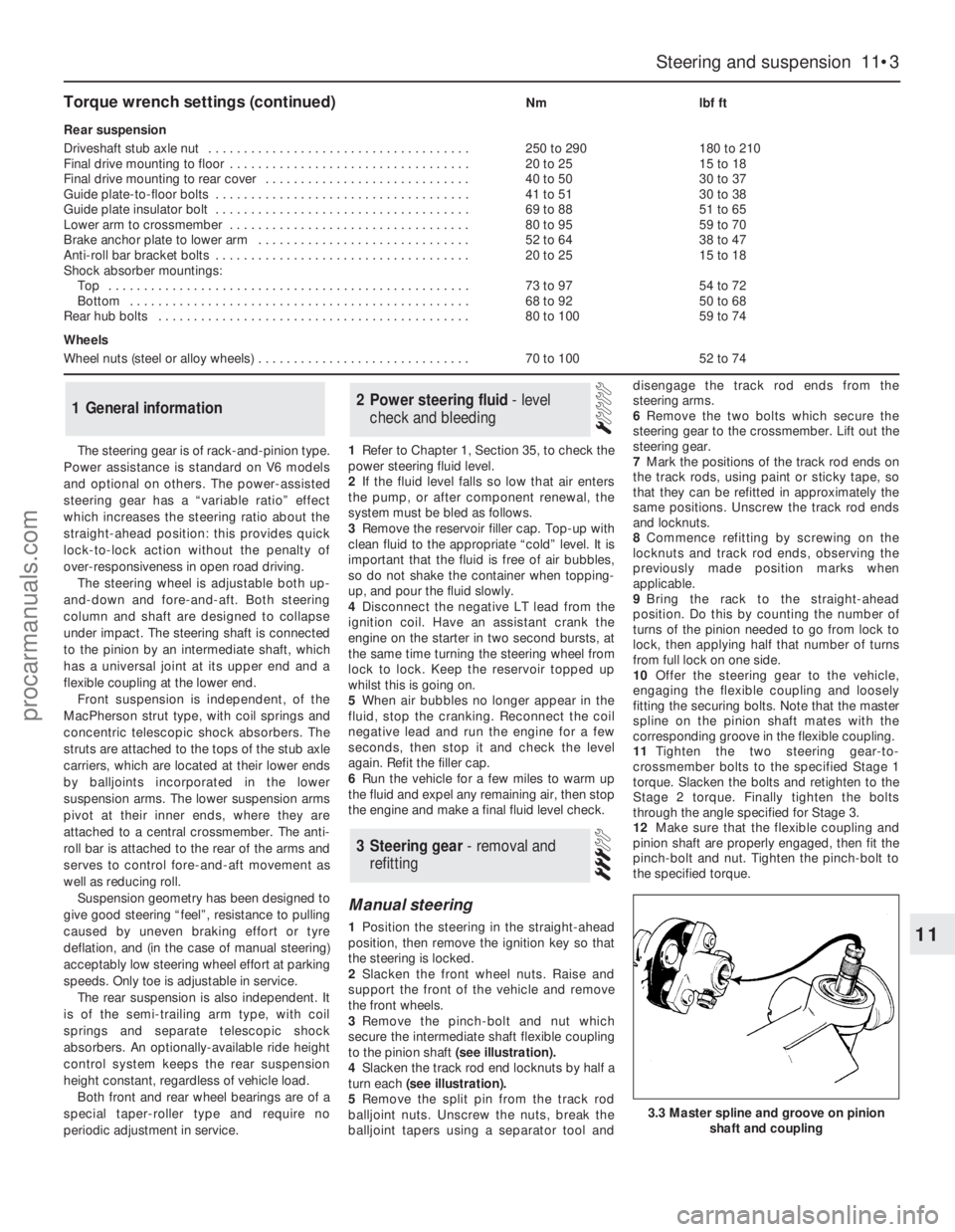
3Remove the pinch-bolt and nut which
secure the intermediate shaft flexible coupling
to the pinion shaft (see illustration).
4Slacken the track rod end locknuts by half a
turn each (see illustration).
5Remove the split pin from the track rod
balljoint nuts. Unscrew the nuts, break the
balljoint tapers using a separator tool anddisengage the track rod ends from the
steering arms.
6Remove the two bolts which secure the
steering gear to the crossmember. Lift out the
steering gear.
7Mark the positions of the track rod ends on
the track rods, using paint or sticky tape, so
that they can be refitted in approximately the
same positions. Unscrew the track rod ends
and locknuts.
8Commence refitting by screwing on the
locknuts and track rod ends, observing the
previously made position marks when
applicable.
9Bring the rack to the straight-ahead
position. Do this by counting the number of
turns of the pinion needed to go from lock to
lock, then applying half that number of turns
from full lock on one side.
10Offer the steering gear to the vehicle,
engaging the flexible coupling and loosely
fitting the securing bolts. Note that the master
spline on the pinion shaft mates with the
corresponding groove in the flexible coupling.
11Tighten the two steering gear-to-
crossmember bolts to the specified Stage 1
torque. Slacken the bolts and retighten to the
Stage 2 torque. Finally tighten the bolts
through the angle specified for Stage 3.
12Make sure that the flexible coupling and
pinion shaft are properly engaged, then fit the
pinch-bolt and nut. Tighten the pinch-bolt to
the specified torque.
3Steering gear - removal and
refitting
2Power steering fluid - level
check and bleeding1General information
Steering and suspension 11•3
11
3.3 Master spline and groove on pinion
shaft and coupling
Torque wrench settings (continued)Nmlbf ft
Rear suspension
Driveshaft stub axle nut . . . . . . . . . . . . . . . . . . . . . . . . . . . . . . . . . . . . .250 to 290180 to 210
Final drive mounting to floor . . . . . . . . . . . . . . . . . . . . . . . . . . . . . . . . . .20 to 2515 to 18
Final drive mounting to rear cover . . . . . . . . . . . . . . . . . . . . . . . . . . . . .40 to 5030 to 37
Guide plate-to-floor bolts . . . . . . . . . . . . . . . . . . . . . . . . . . . . . . . . . . . .41 to 5130 to 38
Guide plate insulator bolt . . . . . . . . . . . . . . . . . . . . . . . . . . . . . . . . . . . .69 to 8851 to 65
Lower arm to crossmember . . . . . . . . . . . . . . . . . . . . . . . . . . . . . . . . . .80 to 9559 to 70
Brake anchor plate to lower arm . . . . . . . . . . . . . . . . . . . . . . . . . . . . . .52 to 6438 to 47
Anti-roll bar bracket bolts . . . . . . . . . . . . . . . . . . . . . . . . . . . . . . . . . . . .20 to 2515 to 18
Shock absorber mountings:
Top . . . . . . . . . . . . . . . . . . . . . . . . . . . . . . . . . . . . . . . . . . . . . . . . . . .73 to 9754 to 72
Bottom . . . . . . . . . . . . . . . . . . . . . . . . . . . . . . . . . . . . . . . . . . . . . . . .68 to 9250 to 68
Rear hub bolts . . . . . . . . . . . . . . . . . . . . . . . . . . . . . . . . . . . . . . . . . . . .80 to 10059 to 74
Wheels
Wheel nuts (steel or alloy wheels) . . . . . . . . . . . . . . . . . . . . . . . . . . . . . .70 to 10052 to 74
procarmanuals.com