1985 FORD GRANADA key
[x] Cancel search: keyPage 148 of 255
reference to horn switch plate retaining
screws. Note that the wheel is retained by a
bolt, not a nut as on earlier models. To gain
access to the bolt, prise out the horn button
and disconnect the wiring connectors.
1This operation is for correcting small errors
in steering wheel centralisation - up to 60°. For
larger errors, remove the steering wheel and
make a rough correction by repositioning the
wheel on refitting.
2Drive the vehicle in a straight line on a level
surface. Note the angle by which the steering
wheel deviates from the desired straight-
ahead position.
3Raise the front of the vehicle by driving it
onto ramps, or with a jack and axle stands
(see “Jacking”).
4Slacken both track rod end locknuts. Also
slacken the steering rack bellows outer clips.
5Make alignment marks between each track
rod end and its rod, so that the amount of
rotation applied can be accurately determined.
6Turn both track rodsin the same direction
to correct the steering wheel position. As a
rough guide, 19°of track rod rotation will
change the steering wheel position by 1°. To
correct error at the steering wheel, rotate both
track rods anti-clockwise (viewed from the
left-hand side of the vehicle), and the reverse
to correct as anti-clockwise errors. Both track
rods must be rotated by the same amount.
7Tighten the bellows clips and the track rod
end locknuts when adjustment is correct.
Lower the vehicle.
1Disconnect the battery negative lead.
2Position the steering in the straight-ahead
position.
3Remove the steering wheel. This is not
essential, but will improve access.
4Working under the bonnet, disconnect the
intermediate shaft universal joint from the
steering column shaft.5Remove the steering column shrouds and
disconnect the switch multi-plugs. Do not
forget the ignition/starter switch.
6Disconnect the bonnet release cable from the
operating lever on the underside of the column.
7Prise out the driver’s side air vent. Remove
the under-dash insulation and trim panel on
the driver’s side, unclipping the bulb failure
module, where applicable.
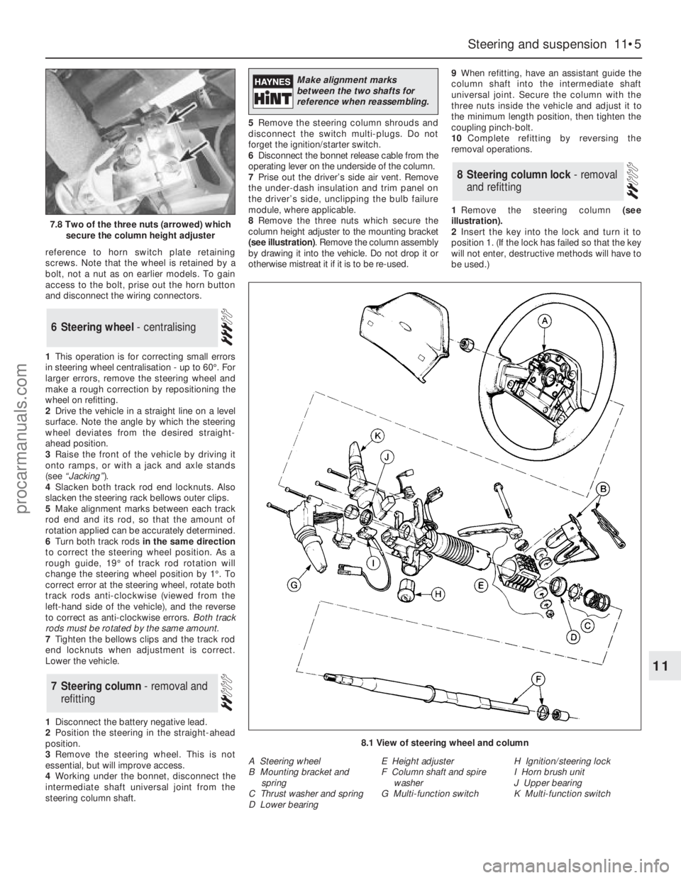
8Remove the three nuts which secure the
column height adjuster to the mounting bracket
(see illustration). Remove the column assembly
by drawing it into the vehicle. Do not drop it or
otherwise mistreat it if it is to be re-used.9When refitting, have an assistant guide the
column shaft into the intermediate shaft
universal joint. Secure the column with the
three nuts inside the vehicle and adjust it to
the minimum length position, then tighten the
coupling pinch-bolt.
10Complete refitting by reversing the
removal operations.
1Remove the steering column (see
illustration).
2Insert the key into the lock and turn it to
position 1. (If the lock has failed so that the key
will not enter, destructive methods will have to
be used.)
8Steering column lock - removal
and refitting
7Steering column - removal and
refitting
6Steering wheel - centralising
Steering and suspension 11•5
11
7.8 Two of the three nuts (arrowed) which
secure the column height adjuster
8.1 View of steering wheel and column
A Steering wheel
B Mounting bracket and
spring
C Thrust washer and spring
D Lower bearingE Height adjuster
F Column shaft and spire
washer
G Multi-function switchH Ignition/steering lock
I Horn brush unit
J Upper bearing
K Multi-function switch
Make alignment marks
between the two shafts for
reference when reassembling.
procarmanuals.com
Page 149 of 255
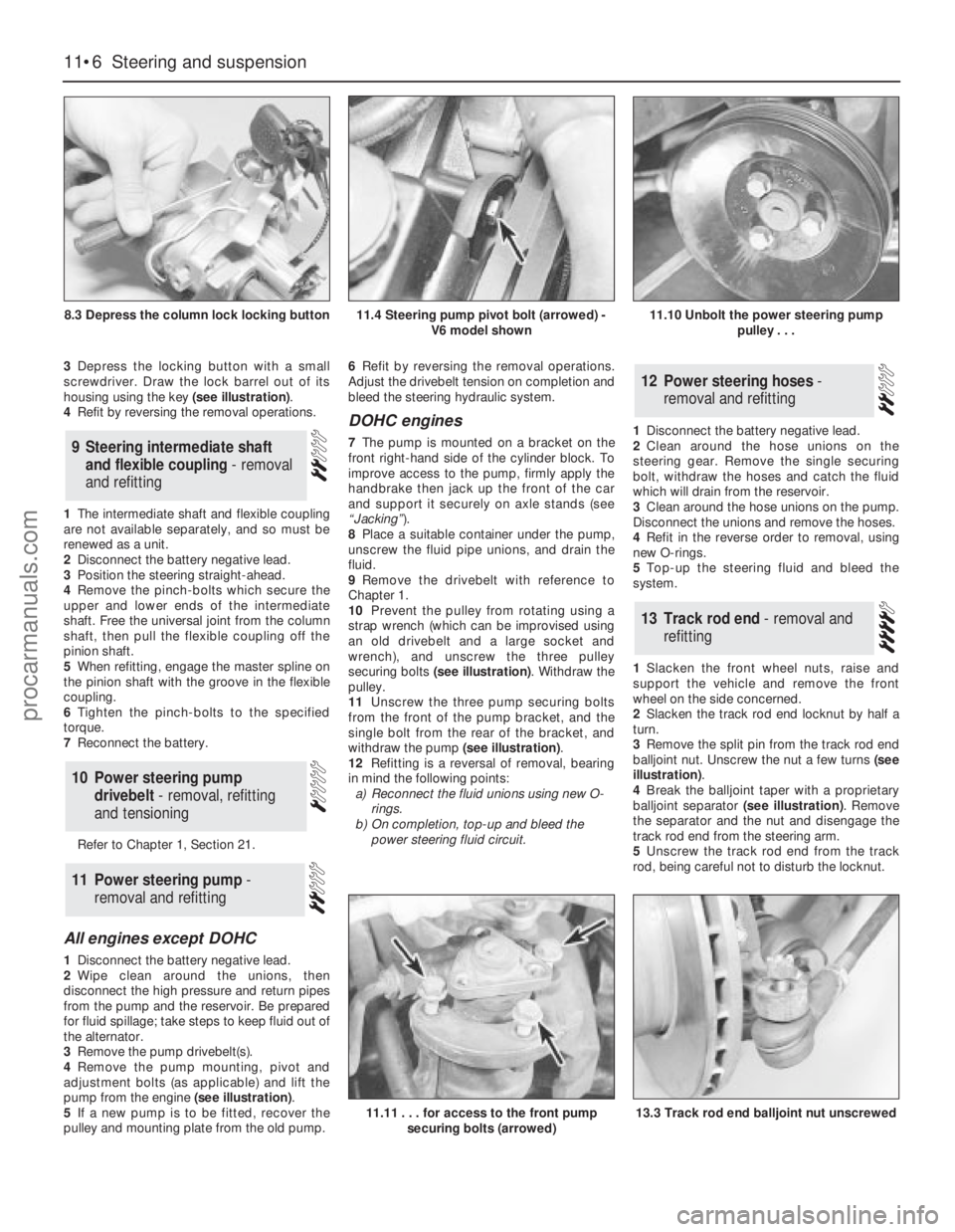
3Depress the locking button with a small
screwdriver. Draw the lock barrel out of its
housing using the key (see illustration).
4Refit by reversing the removal operations.
1The intermediate shaft and flexible coupling
are not available separately, and so must be
renewed as a unit.
2Disconnect the battery negative lead.
3Position the steering straight-ahead.
4Remove the pinch-bolts which secure the
upper and lower ends of the intermediate
shaft. Free the universal joint from the column
shaft, then pull the flexible coupling off the
pinion shaft.
5When refitting, engage the master spline on
the pinion shaft with the groove in the flexible
coupling.
6Tighten the pinch-bolts to the specified
torque.
7Reconnect the battery.
Refer to Chapter 1, Section 21.
All engines except DOHC
1Disconnect the battery negative lead.
2Wipe clean around the unions, then
disconnect the high pressure and return pipes
from the pump and the reservoir. Be prepared
for fluid spillage; take steps to keep fluid out of
the alternator.
3Remove the pump drivebelt(s).
4Remove the pump mounting, pivot and
adjustment bolts (as applicable) and lift the
pump from the engine (see illustration).
5If a new pump is to be fitted, recover the
pulley and mounting plate from the old pump.6Refit by reversing the removal operations.
Adjust the drivebelt tension on completion and
bleed the steering hydraulic system.
DOHC engines
7The pump is mounted on a bracket on the
front right-hand side of the cylinder block. To
improve access to the pump, firmly apply the
handbrake then jack up the front of the car
and support it securely on axle stands (see
“Jacking”).
8Place a suitable container under the pump,
unscrew the fluid pipe unions, and drain the
fluid.
9Remove the drivebelt with reference to
Chapter 1.
10Prevent the pulley from rotating using a
strap wrench (which can be improvised using
an old drivebelt and a large socket and
wrench), and unscrew the three pulley
securing bolts (see illustration). Withdraw the
pulley.
11Unscrew the three pump securing bolts
from the front of the pump bracket, and the
single bolt from the rear of the bracket, and
withdraw the pump (see illustration).
12Refitting is a reversal of removal, bearing
in mind the following points:
a)Reconnect the fluid unions using new O-
rings.
b)On completion, top-up and bleed the
power steering fluid circuit.1Disconnect the battery negative lead.
2Clean around the hose unions on the
steering gear. Remove the single securing
bolt, withdraw the hoses and catch the fluid
which will drain from the reservoir.
3Clean around the hose unions on the pump.
Disconnect the unions and remove the hoses.
4Refit in the reverse order to removal, using
new O-rings.
5Top-up the steering fluid and bleed the
system.
1Slacken the front wheel nuts, raise and
support the vehicle and remove the front
wheel on the side concerned.
2Slacken the track rod end locknut by half a
turn.
3Remove the split pin from the track rod end
balljoint nut. Unscrew the nut a few turns (see
illustration).
4Break the balljoint taper with a proprietary
balljoint separator (see illustration). Remove
the separator and the nut and disengage the
track rod end from the steering arm.
5Unscrew the track rod end from the track
rod, being careful not to disturb the locknut.
13Track rod end - removal and
refitting
12Power steering hoses -
removal and refitting
11Power steering pump -
removal and refitting
10Power steering pump
drivebelt - removal, refitting
and tensioning
9Steering intermediate shaft
and flexible coupling - removal
and refitting
11•6Steering and suspension
8.3 Depress the column lock locking button
11.11 . . . for access to the front pump
securing bolts (arrowed)13.3 Track rod end balljoint nut unscrewed
11.4 Steering pump pivot bolt (arrowed) -
V6 model shown11.10 Unbolt the power steering pump
pulley . . .
procarmanuals.com
Page 153 of 255
1With the strut removed, clamp it in a vice
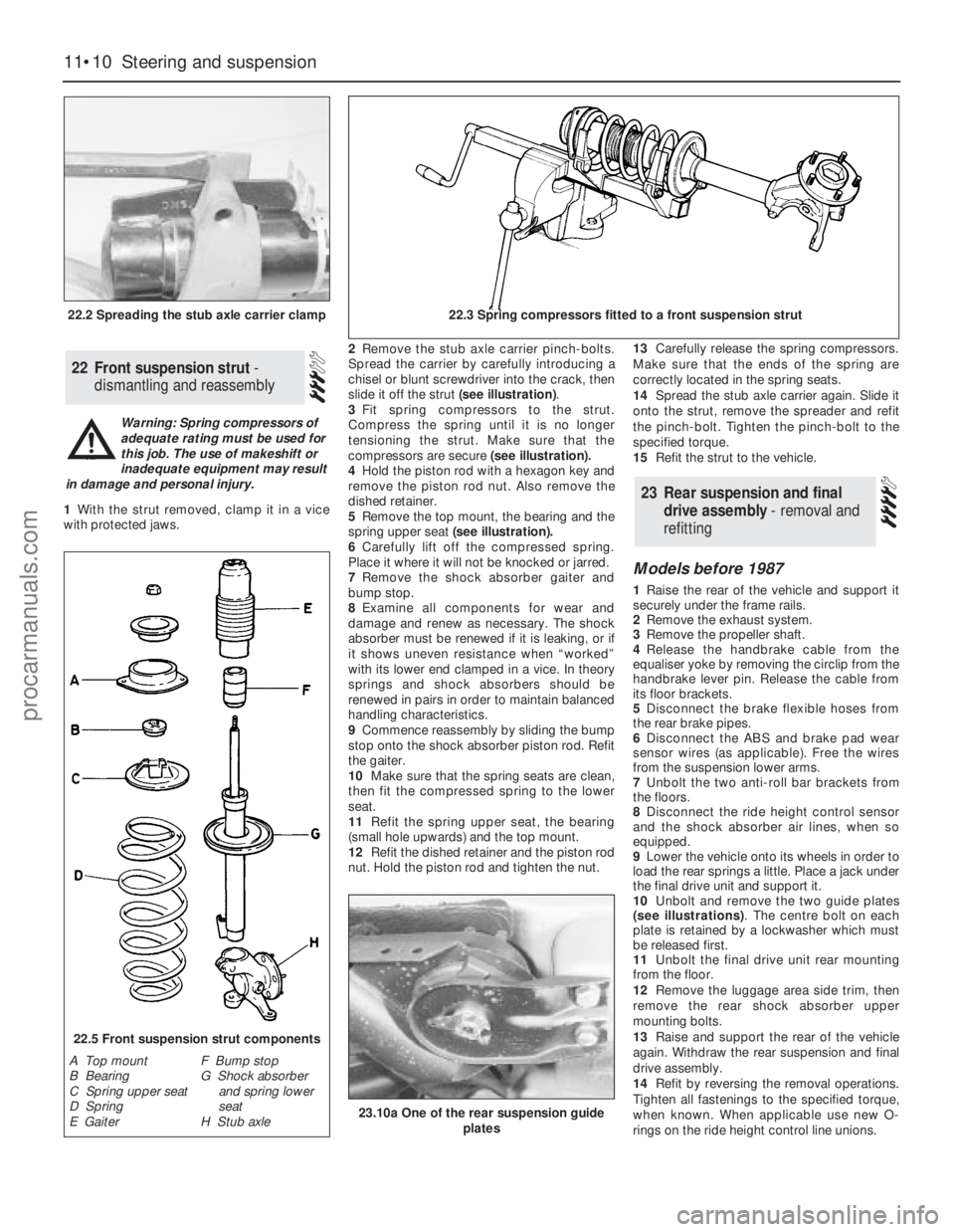
with protected jaws.2Remove the stub axle carrier pinch-bolts.
Spread the carrier by carefully introducing a
chisel or blunt screwdriver into the crack, then
slide it off the strut (see illustration).
3Fit spring compressors to the strut.
Compress the spring until it is no longer
tensioning the strut. Make sure that the
compressors are secure (see illustration).
4Hold the piston rod with a hexagon key and
remove the piston rod nut. Also remove the
dished retainer.
5Remove the top mount, the bearing and the
spring upper seat(see illustration).
6Carefully lift off the compressed spring.
Place it where it will not be knocked or jarred.
7Remove the shock absorber gaiter and
bump stop.
8Examine all components for wear and
damage and renew as necessary. The shock
absorber must be renewed if it is leaking, or if
it shows uneven resistance when “worked”
with its lower end clamped in a vice. In theory
springs and shock absorbers should be
renewed in pairs in order to maintain balanced
handling characteristics.
9Commence reassembly by sliding the bump
stop onto the shock absorber piston rod. Refit
the gaiter.
10Make sure that the spring seats are clean,
then fit the compressed spring to the lower
seat.
11Refit the spring upper seat, the bearing
(small hole upwards) and the top mount.
12Refit the dished retainer and the piston rod
nut. Hold the piston rod and tighten the nut.13Carefully release the spring compressors.
Make sure that the ends of the spring are
correctly located in the spring seats.
14Spread the stub axle carrier again. Slide it
onto the strut, remove the spreader and refit
the pinch-bolt. Tighten the pinch-bolt to the
specified torque.
15Refit the strut to the vehicle.
Models before 1987
1Raise the rear of the vehicle and support it
securely under the frame rails.
2Remove the exhaust system.
3Remove the propeller shaft.
4Release the handbrake cable from the
equaliser yoke by removing the circlip from the
handbrake lever pin. Release the cable from
its floor brackets.
5Disconnect the brake flexible hoses from
the rear brake pipes.
6Disconnect the ABS and brake pad wear
sensor wires (as applicable). Free the wires
from the suspension lower arms.
7Unbolt the two anti-roll bar brackets from
the floors.
8Disconnect the ride height control sensor
and the shock absorber air lines, when so
equipped.
9Lower the vehicle onto its wheels in order to
load the rear springs a little. Place a jack under
the final drive unit and support it.
10Unbolt and remove the two guide plates
(see illustrations). The centre bolt on each
plate is retained by a lockwasher which must
be released first.
11Unbolt the final drive unit rear mounting
from the floor.
12Remove the luggage area side trim, then
remove the rear shock absorber upper
mounting bolts.
13Raise and support the rear of the vehicle
again. Withdraw the rear suspension and final
drive assembly.
14Refit by reversing the removal operations.
Tighten all fastenings to the specified torque,
when known. When applicable use new O-
rings on the ride height control line unions.
23Rear suspension and final
drive assembly - removal and
refitting
22Front suspension strut -
dismantling and reassembly
11•10Steering and suspension
22.2 Spreading the stub axle carrier clamp22.3 Spring compressors fitted to a front suspension strut
22.5 Front suspension strut components
A Top mount
B Bearing
C Spring upper seat
D Spring
E GaiterF Bump stop
G Shock absorber
and spring lower
seat
H Stub axle
Warning: Spring compressors of
adequate rating must be used for
this job. The use of makeshift or
inadequate equipment may result
in damage and personal injury.
23.10a One of the rear suspension guide
plates
procarmanuals.com
Page 159 of 255
important also to keep watch on those parts of
the vehicle not immediately visible, for
instance the underside, inside all the wheel
arches, and the lower part of the engine
compartment.
The basic maintenance routine for the
bodywork is washing - preferably with a lot of
water, from a hose. This will remove all the
loose solids which may have stuck to the
vehicle. It is important to flush these off in
such a way as to prevent grit from scratching
the finish. The wheel arches and underframe
need washing in the same way, to remove any
accumulated mud, which will retain moisture
and tend to encourage rust. Paradoxically
enough, the best time to clean the underframe
and wheel arches is in wet weather, when the
mud is thoroughly wet and soft. In very wet
weather, the underframe is usually cleaned of
large accumulations automatically, and this is
a good time for inspection.
Periodically, except on vehicles with a wax-
based underbody protective coating, it is a
good idea to have the whole of the underframe
of the vehicle steam-cleaned, engine
compartment included, so that a thorough
inspection can be carried out to see what
minor repairs and renovations are necessary.
Steam-cleaning is available at many garages,
and is necessary for the removal of the
accumulation of oily grime, which sometimes
is allowed to become thick in certain areas. If
steam-cleaning facilities are not available,
there are some excellent grease solvents
available which can be brush-applied; the dirt
can then be simply hosed off. Note that these
methods should not be used on vehicles with
wax-based underbody protective coating, or
the coating will be removed. Such vehicles
should be inspected annually, preferably just
prior to Winter, when the underbody should be
washed down, and any damage to the wax
coating repaired. Ideally, a completely fresh
coat should be applied. It would also be worth
considering the use of such wax-based
protection for injection into door panels, sills,
box sections, etc, as an additional safeguard
against rust damage, where such protection is
not provided by the vehicle manufacturer.
After washing paintwork, wipe off with a
chamois leather to give an unspotted clear
finish. A coat of clear protective wax polish will
give added protection against chemical
pollutants in the air. If the paintwork sheen has
dulled or oxidised, use a cleaner/polisher
combination to restore the brilliance of the
shine. This requires a little effort, but such
dulling is usually caused because regular
washing has been neglected. Care needs to
be taken with metallic paintwork, as special
non-abrasive cleaner/polisher is required to
avoid damage to the finish. Always check that
the door and ventilator opening drain holes
and pipes are completely clear, so that water
can be drained out. Brightwork should be
treated in the same way as paintwork.
Windscreens and windows can be kept clear
of the smeary film which often appears, by theuse of proprietary glass cleaner. Never use
any form of wax or other body or chromium
polish on glass.
Mats and carpets should be brushed or
vacuum-cleaned regularly, to keep them free
of grit. If they are badly stained, remove them
from the vehicle for scrubbing or sponging,
and make quite sure they are dry before
refitting. Seats and interior trim panels can be
kept clean by wiping with a damp cloth. If they
do become stained (which can be more
apparent on light-coloured upholstery), use a
little liquid detergent and a soft nail brush to
scour the grime out of the grain of the material.
Do not forget to keep the headlining clean in
the same way as the upholstery. When using
liquid cleaners inside the vehicle, do not over-
wet the surfaces being cleaned. Excessive
damp could get into the seams and padded
interior, causing stains, offensive odours or
even rot. If the inside of the vehicle gets wet
accidentally, it is worthwhile taking some
trouble to dry it out properly, particularly
where carpets are involved. Do not leave oil or
electric heaters inside the vehicle for this
purpose.
Repairs of minor scratches in
bodywork
If the scratch is very superficial, and does
not penetrate to the metal of the bodywork,
repair is very simple. Lightly rub the area of the
scratch with a paintwork renovator, or a very
fine cutting paste, to remove loose paint from
the scratch, and to clear the surrounding
bodywork of wax polish. Rinse the area with
clean water.
Apply touch-up paint to the scratch using a
fine paint brush; continue to apply fine layers
of paint until the surface of the paint in the
scratch is level with the surrounding
paintwork. Allow the new paint at least two
weeks to harden, then blend it into the
surrounding paintwork by rubbing the scratch
area with a paintwork renovator or a very fine
cutting paste. Finally, apply wax polish.
Where the scratch has penetrated right
through to the metal of the bodywork, causing
the metal to rust, a different repair technique is
required. Remove any loose rust from the
bottom of the scratch with a penknife, then
apply rust-inhibiting paint to prevent the
formation of rust in the future. Using a rubber
or nylon applicator, fill the scratch with
bodystopper paste. If required, this paste can
be mixed with cellulose thinners to provide a
very thin paste which is ideal for filling narrow
scratches. Before the stopper-paste in the
scratch hardens, wrap a piece of smoothcotton rag around the top of a finger. Dip the
finger in cellulose thinners, and quickly sweep
it across the surface of the stopper-paste in
the scratch; this will ensure that the surface of
the stopper-paste is slightly hollowed. The
scratch can now be painted over as described
earlier in this Section.
Repairs of dents in bodywork
When deep denting of the vehicle’s
bodywork has taken place, the first task is to
pull the dent out, until the affected bodywork
almost attains its original shape. There is little
point in trying to restore the original shape
completely, as the metal in the damaged area
will have stretched on impact, and cannot be
reshaped fully to its original contour. It is
better to bring the level of the dent up to a
point which is about 3 mm below the level of
the surrounding bodywork. In cases where the
dent is very shallow anyway, it is not worth
trying to pull it out at all. If the underside of the
dent is accessible, it can be hammered out
gently from behind, using a mallet with a
wooden or plastic head. Whilst doing this,
hold a suitable block of wood firmly against
the outside of the panel, to absorb the impact
from the hammer blows and thus prevent a
large area of the bodywork from being “belled-
out”.
Should the dent be in a section of the
bodywork which has a double skin, or some
other factor making it inaccessible from
behind, a different technique is called for. Drill
several small holes through the metal inside
the area - particularly in the deeper section.
Then screw long self-tapping screws into the
holes, just sufficiently for them to gain a good
purchase in the metal. Now the dent can be
pulled out by pulling on the protruding heads
of the screws with a pair of pliers.
The next stage of the repair is the removal
of the paint from the damaged area, and from
an inch or so of the surrounding “sound”
bodywork. This is accomplished most easily
by using a wire brush or abrasive pad on a
power drill, although it can be done just as
effectively by hand, using sheets of abrasive
paper. To complete the preparation for filling,
score the surface of the bare metal with a
screwdriver or the tang of a file, or
alternatively, drill small holes in the affected
area. This will provide a really good “key” for
the filler paste.
To complete the repair, see the Section on
filling and respraying.
Repairs of rust holes or gashes in
bodywork
Remove all paint from the affected area, and
from an inch or so of the surrounding “sound”
bodywork, using an abrasive pad or a wire
brush on a power drill. If these are not
available, a few sheets of abrasive paper will
do the job most effectively. With the paint
removed, you will be able to judge the severity
of the corrosion, and therefore decide whether
to renew the whole panel (if this is possible) or
4Minor body damage - repair
3Maintenance - upholstery and
carpets
12•2Bodywork and fittings
procarmanuals.com
Page 164 of 255
the door through the large cut-out. Further
displacement or removal of the foamrubber
sheet may be necessary.
7Refit in the reverse order to removal, noting
the following points:
a)Apply a little grease to the interior handle
rods where they pass through the plastic
bushes
b)When securing the interior handle, have
the locking lever in the “unlocked”
position, hold the assembly forwards as
far as itwill go and tighten the securing
screw
c)Check all functions before refitting the trim
panel.
Door weatherstrip
1Open the door and remove the weatherstrip
securing screw from the latch end. In the case
of the rear door, also remove the screw from
the hinge end.
2Carefully lift the latch end of the
weatherstrip and pull it off the door.
3Refit by reversing the removal operations,
using your palm to seat the weatherstrip.
Aperture weatherstrip
4Open the door. Remove the scuff plate
securing screws from the bottom of the door
aperture.
5Pull the old weatherstrip out of the door
aperture.
6Fit the new weatherstrip, starting at the
right-angled corner at the top. Fit the
weatherstrip to the other corners and bends,
leaving the straight sections until last.
7Refit the scuff, plate securing screws.
All models except Estate
1Disconnect the battery negative lead.
2Remove the tailgate interior trim panel,
which is secured by eleven screws.
3Remove the six nuts which secure the
tailgate handle. Remove the handle and
recover the gasket.
4Disconnect the tailgate lock switch multi-
plug. Release the switch locking tab and
remove the switch.
5Disconnect the operating rod from the lock
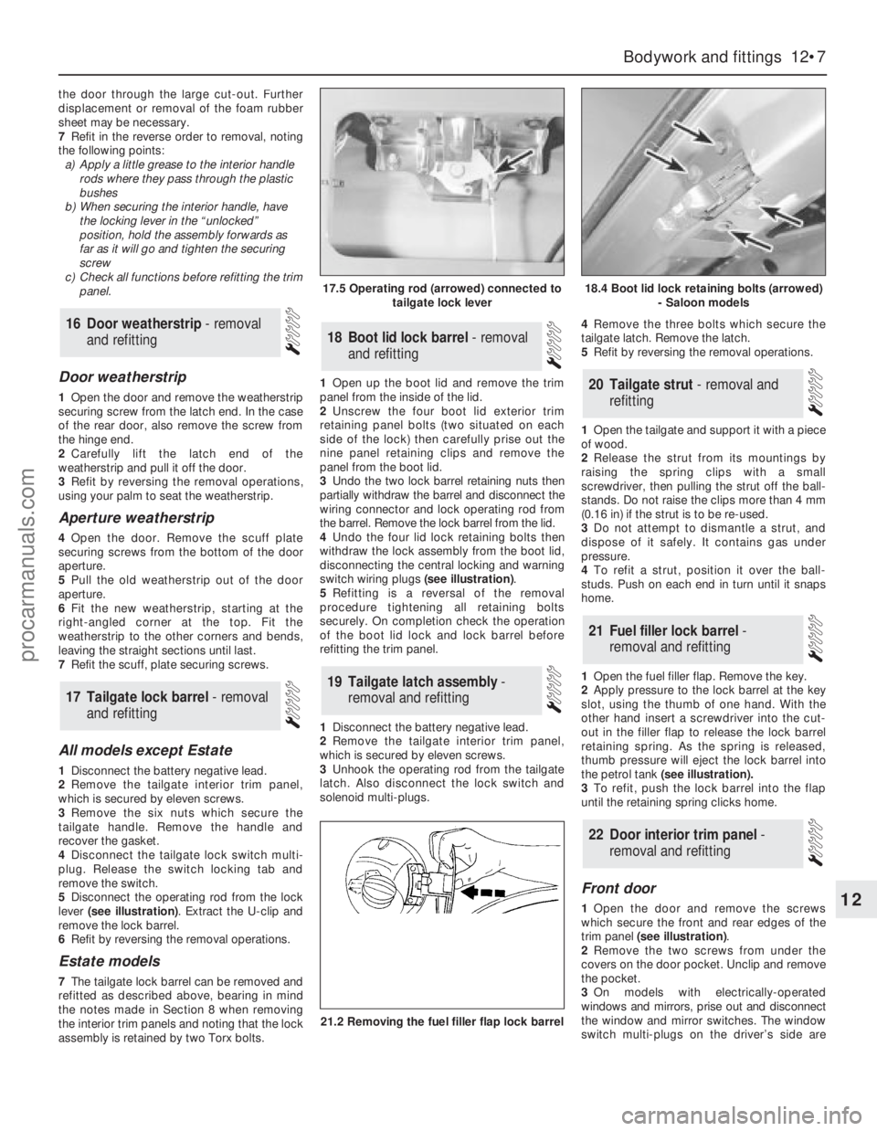
lever (see illustration). Extract the U-clip and
remove the lock barrel.
6Refit by reversing the removal operations.
Estate models
7The tailgate lock barrel can be removed and
refitted as described above, bearing in mind
the notes made in Section 8 when removing
the interior trim panels and noting that the lock
assembly is retained by two Torx bolts.1Open up the boot lid and remove the trim
panel from the inside of the lid.
2Unscrew the four boot lid exterior trim
retaining panel bolts (two situated on each
side of the lock) then carefully prise out the
nine panel retaining clips and remove the
panel from the boot lid.
3Undo the two lock barrel retaining nuts then
partially withdraw the barrel and disconnect the
wiring connector and lock operating rod from
the barrel. Remove the lock barrel from the lid.
4Undo the four lid lock retaining bolts then
withdraw the lock assembly from the boot lid,
disconnecting the central locking and warning
switch wiring plugs (see illustration).
5Refitting is a reversal of the removal
procedure tightening all retaining bolts
securely. On completion check the operation
of the boot lid lock and lock barrel before
refitting the trim panel.
1Disconnect the battery negative lead.
2Remove the tailgate interior trim panel,
which is secured by eleven screws.
3Unhook the operating rod from the tailgate
latch. Also disconnect the lock switch and
solenoid multi-plugs.4Remove the three bolts which secure the
tailgate latch. Remove the latch.
5Refit by reversing the removal operations.
1Open the tailgate and support it with a piece
of wood.
2Release the strut from its mountings by
raising the spring clips with a small
screwdriver, then pulling the strut off the ball-
stands. Do not raise the clips more than 4 mm
(0.16 in) if the strut is to be re-used.
3Do not attempt to dismantle a strut, and
dispose of it safely. It contains gas under
pressure.
4To refit a strut, position it over the ball-
studs. Push on each end in turn until it snaps
home.
1Open the fuel filler flap. Remove the key.
2Apply pressure to the lock barrel at the key
slot, using the thumb of one hand. With the
other hand insert a screwdriver into the cut-
out in the filler flap to release the lock barrel
retaining spring. As the spring is released,
thumb pressure will eject the lock barrel into
the petrol tank (see illustration).
3To refit, push the lock barrel into the flap
until the retaining spring clicks home.
Front door
1Open the door and remove the screws
which secure the front and rear edges of the
trim panel (see illustration).
2Remove the two screws from under the
covers on the door pocket. Unclip and remove
the pocket.
3On models with electrically-operated
windows and mirrors, prise out and disconnect
the window and mirror switches. The window
switch multi-plugs on the driver’s side are
22Door interior trim panel -
removal and refitting
21Fuel filler lock barrel -
removal and refitting
20Tailgate strut - removal and
refitting
19Tailgate latch assembly -
removal and refitting
18Boot lid lock barrel - removal
and refitting
17Tailgate lock barrel - removal
and refitting
16Door weatherstrip - removal
and refitting
Bodywork and fittings 12•7
12
17.5 Operating rod (arrowed) connected to
tailgate lock lever18.4 Boot lid lock retaining bolts (arrowed)
- Saloon models
21.2 Removing the fuel filler flap lock barrel
procarmanuals.com
Page 167 of 255
Later models
7The radiator grille of these models can be
removed and refitted as described above,
noting that it will also be necessary to remove
the headlamp wiper arms (where fitted) before
the grille can be removed. To remove a wiper
arm, lift the cover to gain access to the
retaining nut then undo the nut and pull the
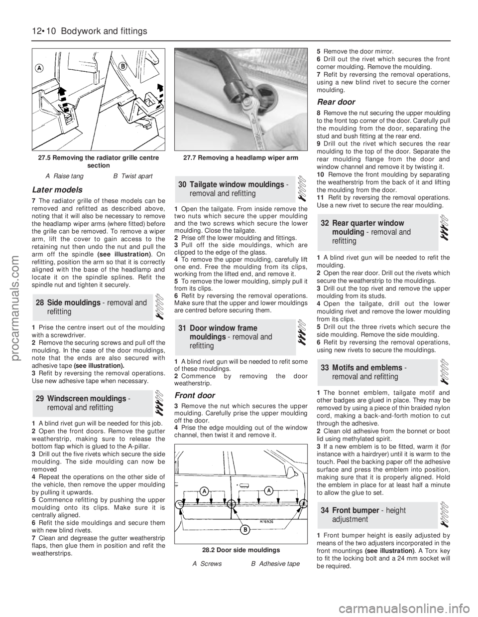
arm off the spindle (see illustration). On
refitting, position the arm so that it is correctly
aligned with the base of the headlamp and
locate it on the spindle splines. Refit the
spindle nut and tighten it securely.
1Prise the centre insert out of the moulding
with a screwdriver.
2Remove the securing screws and pull off the
moulding. In the case of the door mouldings,
note that the ends are also secured with
adhesive tape (see illustration).
3Refit by reversing the removal operations.
Use new adhesive tape when necessary.
1A blind rivet gun will be needed for this job.
2Open the front doors. Remove the gutter
weatherstrip, making sure to release the
bottom flap which is glued to the A-pillar.
3Drill out the five rivets which secure the side
moulding. The side moulding can now be
removed
4Repeat the operations on the other side of
the vehicle, then remove the upper moulding
by pulling it upwards.
5Commence refitting by pushing the upper
moulding onto its clips. Make sure it is
centrally aligned.
6Refit the side mouldings and secure them
with new blind rivets.
7Clean and degrease the gutter weatherstrip
flaps, then glue them in position and refit the
weatherstrips.1Open the tailgate. From inside remove the
two nuts which secure the upper moulding
and the two screws which secure the lower
moulding. Close the tailgate.
2Prise off the lower moulding and fittings.
3Pull off the side mouldings, which are
clipped to the edge of the glass.
4To remove the upper moulding, carefully lift
one end. Free the moulding from its clips,
working from the lifted end, and remove it.
5To remove the lower moulding, simply pull it
from its clips.
6Refit by reversing the removal operations.
Make sure that the upper and lower mouldings
are centred before securing them.
1A blind rivet gun will be needed to refit some
of these mouldings.
2Commence by removing the door
weatherstrip.
Front door
3Remove the nut which secures the upper
moulding. Carefully prise the upper moulding
off the door.
4Prise the edge moulding out of the window
channel, then twist it and remove it. 5Remove the door mirror.
6Drill out the rivet which secures the front
corner moulding. Remove the moulding.
7Refit by reversing the removal operations,
using a new blind rivet to secure the corner
moulding.
Rear door
8Remove the nut securing the upper moulding
to the front top corner of the door. Carefully pull
the moulding from the door, separating the
stud and bush fitting at the rear end.
9Drill out the rivet which secures the rear
moulding to the top of the door. Separate the
rear moulding flange from the door and
window channel and remove it by twisting it.
10Remove the front moulding by separating
the weatherstrip from the back of it and lifting
the moulding from the door.
11Refit by reversing the removal operations.
Use a new rivet to secure the rear moulding.
1A blind rivet gun will be needed to refit the
moulding.
2Open the rear door. Drill out the rivets which
secure the weatherstrip to the mouldings.
3Drill out the top rivet and remove the upper
moulding from its studs.
4Open the tailgate, drill out the lower
moulding rivet and remove the lower moulding
from its clips.
5Drill out the three rivets which secure the
side moulding. Remove the side moulding.
6Refit by reversing the removal operations,
using new rivets to secure the mouldings.
1The bonnet emblem, tailgate motif and
other badges are glued in place. They may be
removed by using a piece of thin braided nylon
cord, making a back-and-forth motion to cut
through the adhesive.
2Clean old adhesive from the bonnet or boot
lid using methylated spirit.
3If a new emblem is to be fitted, warm it (for
instance with a hairdryer) until it is warm to the
touch. Peel the backing paper off the adhesive
surface and press the emblem into position,
making sure that it is properly aligned. Hold
the emblem in place for at least half a minute
to allow the glue to set.
1Front bumper height is easily adjusted by
means of the two adjusters incorporated in the
front mountings (see illustration). A Torx key
to fit the locking bolt and a 24 mm socket will
be required.
34Front bumper - height
adjustment
33Motifs and emblems -
removal and refitting
32Rear quarter window
moulding - removal and
refitting
31Door window frame
mouldings - removal and
refitting
30Tailgate window mouldings -
removal and refitting
29Windscreen mouldings -
removal and refitting
28Side mouldings - removal and
refitting
12•10Bodywork and fittings
27.5 Removing the radiator grille centre
section
A Raise tangB Twist apart
27.7 Removing a headlamp wiper arm
28.2 Door side mouldings
A ScrewsB Adhesive tape
procarmanuals.com
Page 190 of 255
Heated rear window switch
Models before April 1992
50Remove the instrument panel surround,
which is secured by four screws.
51Carefully prise the switch from its location,
disconnect the multi-plug and remove it.
Models from April 1992
52Using a small flat-bladed screwdriver,
carefully prise the switch out of the centre
facia vent panel and disconnect the wiring
connector.
53On refitting, reconnect the wiring
connector and push the switch in until it clicks
into position.
Foglight switch(es)
54These are removed in the same way as the
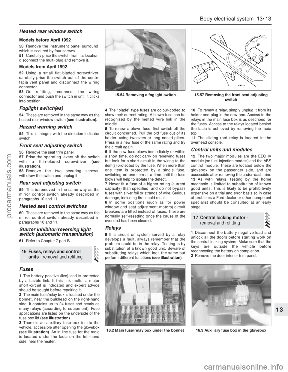
heated rear window switch (see illustration).
Hazard warning switch
55This is integral with the direction indicator
switch.
Front seat adjusting switch
56Remove the seat trim panel.
57Prise the operating levers off the switch
with a thin-bladed screwdriver (see
illustration).
58Remove the two securing screws,
withdraw the switch and unplug it.
Rear seat adjusting switch
59This is removed in the same way as the
mirror control switch already described in
paragraphs 10 and 11.
Heated seat control switches
60These are removed in the same way as the
mirror control switch already described in
paragraphs 10 and 11.
Starter inhibitor/reversing light
switch (automatic transmission)
61Refer to Chapter 7 part B.
Fuses
1The battery positive (live) lead is protected
by a fusible link. If this link melts, a major
short-circuit is indicated and expert advice
should be sought before repairing it.
2The main fuse/relay box is located under the
bonnet, near the bulkhead on the right-hand
side. It contains up to 24 fuses and nearly as
many relays (according to equipment). Fuse
applications are listed on the underside of the
fuse box lid (see illustration).
3There is an auxiliary fuse box inside the
vehicle, accessible after opening the glovebox
(see illustration). An in-line fuse for the radio
is located under the facia on the left-hand
side, near the heater.4The“blade” type fuses are colour-coded to
show their current rating. A blown fuse can be
recognised by the melted wire link in the
middle.
5To renew a blown fuse, first switch off the
circuit concerned. Pull the old fuse out of its
holder, using tweezers or long-nosed pliers.
Press in a new fuse of the same rating and try
the circuit again.
6If the new fuse blows immediately or within
a short time, do not carry on renewing fuses
but look for a short-circuit in the wiring to the
item(s) protected by the fuse. When more than
one item is protected by a single fuse,
switching on one item at a time until the fuse
blows will help to isolate the defect.
7Never fit a fuse of a higher rating (current
capacity) than specified, and do not bypass
fuses with silver foil or strands of wire. Serious
damage, including fire, could result.
8In some positions (such as for power
window and seat adjustment motors) circuit
breakers are fitted instead of fuses. These are
normally self-resetting once the cause of the
overload has been cleared.
Relays
9If a circuit or system served by a relay
develops a fault, always remember that the
problem could be in the relay. Testing is by
substitution of a known good unit. Beware of
substituting relays which look the same but
perform different functions(see illustration).10To renew a relay, simply unplug it from its
holder and plug in the new one. Access to the
relays in the main fuse box is as described for
the fuses. Access to the relays located behind
the facia is achieved by removing the facia
top.
11The sliding roof relay is located in the
overhead console.
Control units and modules
12The two major modules are the EEC IV
module (on fuel-injection models) and the ABS
control module. These are located below the
glovebox on the passenger side, and are
accessible after removing the under-dash trim.
13As with relays, testing by the home
mechanic is limited to substitution of known
good units. This is likely to be prohibitively
expensive on a trial and error basis so in case
of problems a Ford dealer or other competent
specialist should be consulted at an early
stage.
1Disconnect the battery negative lead and
unlock all the doors before starting work on
the central locking system. Make sure that the
keys are outside the vehicle before
reconnecting the battery on completion.
2Remove the door interior trim panel.
17Central locking motor -
removal and refitting
16Fuses, relays and control
units - removal and refitting
Body electrical system 13•13
13
15.54 Removing a foglight switch15.57 Removing the front seat adjusting
switch
16.2 Main fuse/relay box under the bonnet16.3 Auxiliary fuse box in the glovebox
procarmanuals.com
Page 199 of 255
High frequency units
14Remove the instrument panel surround
and the facia top.
15Remove the two screws which secure the
speaker bracket. Disconnect the wiring and
withdraw the speaker and bracket together.
The screws which secure the speaker to the
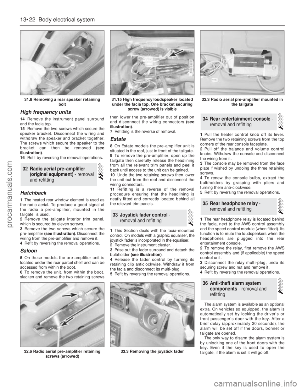
bracket can then be removed (see
illustration).
16Refit by reversing the removal operations.
Hatchback
1The heated rear window element is used as
the radio aerial. To produce a good signal at
the radio a pre-amplifier, mounted in the
tailgate, is used.
2Remove the tailgate interior trim panel,
which is secured by eleven screws.
3Remove the two screws which secure the
pre-amplifier (see illustration). Disconnect the
wiring from the pre-amplifier and remove it.
4Refit by reversing the removal operations.
Saloon
5On these models the pre-amplifier unit is
located under the rear parcel shelf and can be
accessed from within the boot.
6To remove the unit, from within the boot,
slacken and remove the two retaining screwsthen lower the pre-amplifier out of position
and disconnect the wiring connectors (see
illustration).
7Refitting is the reverse of removal.
Estate
8On Estate models the pre-amplifier unit is
situated in the roof, just in front of the tailgate.
9To remove the pre-amplifier, open up the
tailgate then carefully release the headlining
from all the relevant trim panels and peel it
back until access to the unit can be gained.
10Undo the two retaining screws then lower
the unit out from the roof and disconnect the
wiring connectors.
11Refitting is a reverse of the removal
procedure ensuring that the headlining is
neatly fitted and correctly located behind all
the relevant trim panels.
1This Section deals with the facia-mounted
control. On models with a graphic equaliser, the
joystick fader is incorporated in the equaliser.
2Remove the instrument cluster.
3Prise out the fader surround and detach the
bulbholder (see illustration).
4Release the fader control by turning its
retaining clip anticlockwise. Withdraw it from
the facia and disconnect its multi-plug.
5Refit by reversing the removal operations.1Pull the heater control knob off its lever.
Remove the two retaining screws from the top
corners of the rear console faceplate.
2Pull off the balance and volume control
knobs. Withdraw the console and disconnect
the wiring from it.
3The console may be removed from the face
plate if wished by undoing the three retaining
screws.
4To renew the console bulbs, extract the
bulbholders by grasping with pliers and
turning them anti-clockwise.
5Refit by reversing the removal operations.
1The rear headphone relay is located behind
the facia, next to the AWS control assembly
and the speed control module (when fitted). Its
function is to mute the loudspeakers when the
headphones are plugged into the rear
entertainment console.
2To remove the relay, first remove the AWS
control assembly and (if applicable) the speed
control unit.
3Disconnect the relay multi-plug, undo its
securing screw and nut and remove it.
4Refit by reversing the removal operations.
The alarm system is available as an optional
extra. On vehicles so equipped, the alarm is
automatically set by locking the driver’s or
front passenger’s door with the key. After a
brief delay (approximately 20 seconds), the
alarm will be set off if the doors, bonnet or
tailgate are opened.
The only way to disarm the alarm system is
by unlocking one of the front doors with the
key. Even if the key is used to open the
tailgate, if the alarm is set it will go off.
36Anti-theft alarm system
components - removal and
refitting
35Rear headphone relay -
removal and refitting
34Rear entertainment console -
removal and refitting
33Joystick fader control -
removal and refitting
32Radio aerial pre-amplifier
(original equipment) - removal
and refitting
13•22Body electrical system
31.8 Removing a rear speaker retaining
bolt
32.6 Radio aerial pre-amplifier retaining
screws (arrowed)33.3 Removing the joystick fader
31.15 High frequency loudspeaker located
under the facia top. One bracket securing
screw (arrowed) is visible32.3 Radio aerial pre-amplifier mounted in
the tailgate
procarmanuals.com