Page 17 of 79

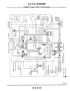
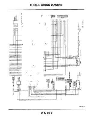
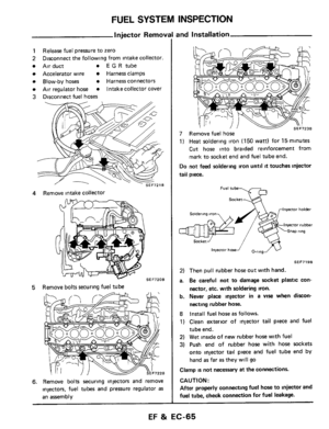
E. C. C. S. DESCRIPTION
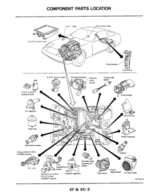
E.C.C.S. Corn
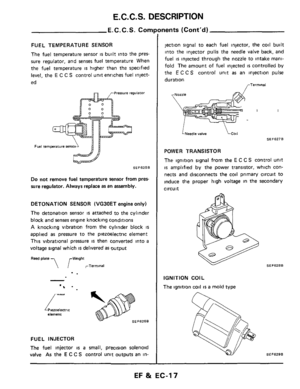
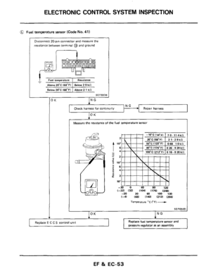
FUEL TEMPERATURE SENSOR
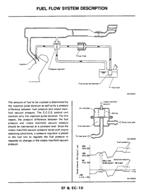
The fuel temperature sensor is built into the pres-
sure regulator, and senses fuel temperature When
the fuel temperature
IS higher than the specified
level, the
E C C S control unit enriches fuel inject-
ed
Pressure regulator
Fuel temprature $ens
SEF625B
Do not remove fuel temperature sensor from pres-
sure regulator. Always replace as
an assembly.
DETONATION SENSOR (VG30ET engine only)
The detonation sensor
is attached to the cylinder
block and senses engine knocking conditions
A knocking vibration from the cylinder block is
applied as pressure to the piezoelectric element
This vibrational pressure
IS then converted into a
voltage signal which is delivered as output
Reed plate ,, ,-Weight
rTerminal
-.
Piezoelectric element
SEFSZSB
/-
FUEL INJECTOR
The
fuel injector is a small, precision solenoid
valve As the
E C C S control unit outputs an in-
lnents (Cont’d)
jection signal to each fuel injector, the coil built
into the injector pulls the needle valve back, and
fuel
is injected through the nozzle to intake mani-
fold The amount of fuel injected
is controlled by
the
E C C S control unit as an injection pulse
duration
<-Nozzle
LNeedle valve
SEF627B
POWER TRANSISTOR
The ignition signal from the
E C C S control unit
is amplified by the power transistor, which con-
nects and disconnects the coil primary circuit to
induce the proper high voltage in the secondary
circuit
SEFSZBB
IGNITION COIL
The ignition coil
IS a mold type
EF & EC-17
Page 18 of 79

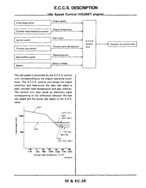
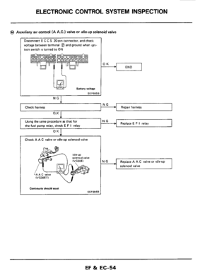
The
A A C valve is attached to the intake collec-
tor The E C CS control unit actuates AAC")
E. C. C. S. DESCRIPTION
E.C.C.S. Corn1
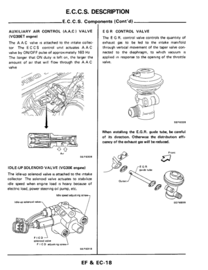
AUXILIARY AIR CONTROL (A.A.C 1 VALVE
(VG30ET
engine)
The
A A C valve is attached to the intake collec-
tor The E C CS control unit actuates AAC
valve by ON/OFF pulse of approximately 160 Hz
The longer that ON duty is left on, the larger the
amount of
air that will flow through the A A C
valve
1
AV SEF630B
IDLE-UP SOLENOID VALVE (VG30E engine)
The idle-up solenoid valve is attached to the intake
collector The solenoid valve actuates to stabilize
idle speed when engine load
is heavy because of
electric load, power steering oil pump, etc.
7
idle speed adiuning screw
ldleup solenoid valve
SEF631 B
FICDJ solenoid valve
F I C D adjusling screw
nents (Cont'd)
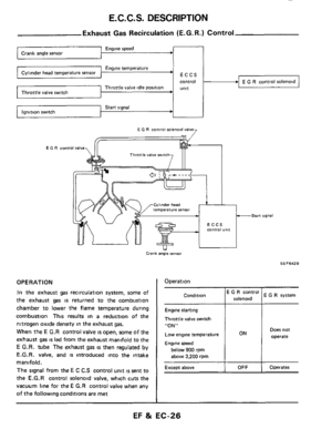
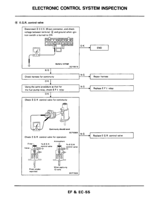
E G R CONTROL VALVE
The E G R. control valve controls the quantity of
exhaust
gas to be led to the intake manifold
through vertical movement of the taper valve con-
nected to the diaphragm, to which vacuum
IS
applied in response to the opening of the throttle
valve.
SEF632B
When installing the E.G.R. guide tube, be careful
of its direction. Otherwise the distribution effi-
ciency of the exhaust gas will be reduced.
SEF689B
EF 8i EC-18
Page 19 of 79

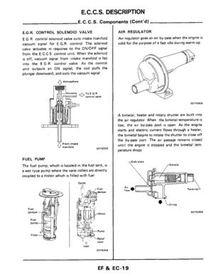
E.G.R. CONTROL SOLENOID VALVE
E G R control solenoid valve cuts intake manifold
vacuum signal for
E G.R control The solenoid
valve")
E. C. C. S. DESCRIPTION
E.C.C.S. Components (Cont’d)
E.G.R. CONTROL SOLENOID VALVE
E G R control solenoid valve cuts intake manifold
vacuum signal for
E G.R control The solenoid
valve actuates in response to the ON/OFF signal
from
the E C.C S control unit. When the solenoid
is off, vacuum signal from intake manifold is fed
into the
E G R control valve As the control
unit outputs an ON signal, the coil pulls the
plunger downward, and cuts the vacuum signal
9 Atmosphere
ToEGR control valve
From intake
SEF6336 0 manifold
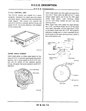
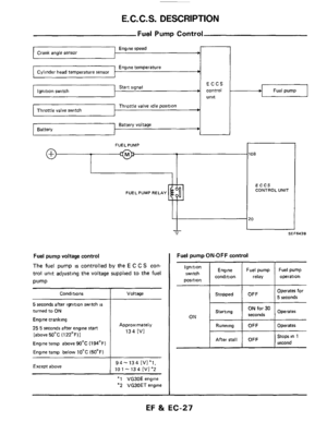
FUEL PUMP
The fuel pump, which is located in the fuel tank, IS
a wet type pump where the vane rollers are directly
coupled to
a motor which is filled with fuel
1 Outlet A
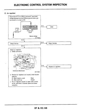
AIR REGULATOR
Air regulator gives an air by-pass when the engine is
cold for the purpose of a fast idle during warm-up
SE F635 B
A bimetal, heater and rotary shutter are built into
the air regulator When the bimetal temperature
IS
low,
the air by-pass port is open As the engine
starts and electric current flows through a heater,
the bimetal begins to rotate the shutter
to close off
the by-pass port The air passage remalns closed
until the engine
is stopped and the bimetal tem-
perature drops
SEF636B
EF & EC-19
Page 20 of 79

E.C.C.S. DESCRIPTION
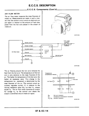
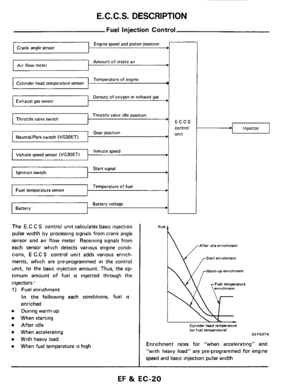
Fuel Injection Control
Temperature of engine Cylinder head temperature sensor
Density of oxygen in exhaust gas Exhaust gas sensor
Throttle valve idle position ' Throttle valve switch
Engine speed and piston position
Amount of intake air Air flow meter
ECCS
I I
I
control
Gear position unit NeutraVPark switch (VG30ET) I I
Vehicle speed
Start signal
Temperature of fuel
Battery voltage Battery
The E.C C S control unit calculates basic injection
pulse
width by processing signals from crank angle
sensor and air flow meter Receiving signals from
each sensor which detects various engine condi-
tions,
E C.C S control unit adds various enrich-
ments, which are pre-programmed
in the control
unit, to the basic injection amount. Thus, the op-
timum amount of fuel is injected through the
injectors.
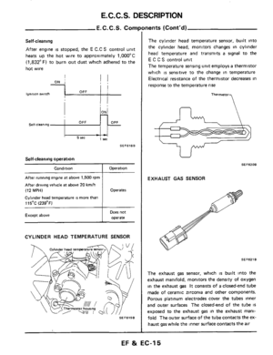
1 ) Fuel enrichment
In the following each conditions, fuel is
enriched
e During warm-up
When starting
After idle
e When accelerating
e With heavy load
e When fuel temperature is high
.I Injector
Rlch
' \/ .-Warm-u~ enrichment
Cylmder head temperature (or fuel temperature1 SE F637 0
Enrichment rates for "when accelerating" and
"with heavy load" are pre-programmed for engine
speed and basic injection pulse
width
EF & EC-20
Page 21 of 79
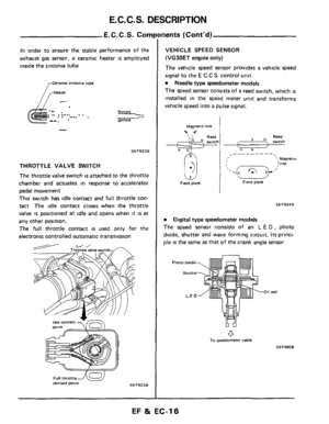
 Fuel shut-off
 is accomplished under the follow-
ing conditions.
a Du")
E. C. C. S. DESCRIPTION
Deceleration from @
Deceleration from @
Deceleration from 0 or @
Fuel Injection
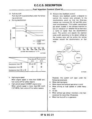
2) Fuel shut-off
Fuel shut-off is accomplished under the follow-
ing conditions.
a During deceleration
@ and @ 62
0 (E9
- -
- -.. . . . ._ '. .
VG30ET (MITI
VG30E
_-- VGXIET IA/Tl
-20 0 20 40 60 SO 100
(-41 1321 (681 11041 (1401 (1761 12121
Cvlinder head IemPerature "C 1°F)
SEF638B
b High engine speed
When engine speed is more than 6,500 rpm,
fuel
is shut-off for safety reasons
High vehicle speed
(VG30ET engine only)
When vehicle speed
is more than 220 km/h
(137 MPH), fuel is shut-off for safety reasons
c
mtrol (Cont'd)
3) Mixture ratio feedback control
Mixture ratio feedback system is designed to
control the mixture ratio precisely to the
*stoichiometric point
so that the three-way
!catalyst can minimize
CO, HC and NOx emis-
';ions simultaneously This system
uses exhaust
gas senwr located in the exhaust manifold to
give an indication of whether the air-fuel ratio
is richer or leaner than the stoichiometric
point The control unit adjusts the injection
pulse width according to the sensor voltage so
the mixture ratio will be within the narrow
window around the stoichiometric
air fuel
ratio
eontroi
Injector
0
Combustm
Engme
However, this system will open under the
following conditions
When starting engine.
When engine and exhaust
gas sensor is cold
When driving
at high speeds or under heavy
load.
At idle
When exhaust
gas sensor monitors a too lean
condition for more than
10 seconds.
When fuel shut-off
is in omration
EF & EC-21
Page 22 of 79
-
4) Simultaneous injection and group injection
On the VG30ET engines, two types of fuel
injection systems
are used - simultaneous
injectio")
E.C.C.S. DESCRIPTION
-Fuel injection Control (Cont'd)-
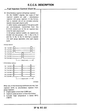
4) Simultaneous injection and group injection
On the VG30ET engines, two types of fuel
injection systems
are used - simultaneous
injection and group injection. In the former,
fuel is injected into all six cylinders simulta-
neously twice each engine cycle
In other words, pulse signals
of the same width
are simultaneously transmitted from the
E C.C.S. control unit to the six injectors two
times for each engine cycle
In the group injection system, six injectors are
divided into
two groups - No 1, No. 2, No. 3
and No 4, No 5, No 6 And fuel is injected
into each group separately once each engine
cycle
Group injection
NO 1 cylmder u
No 5 cylinder n
No 6cylinder _n
No 1 cylinder u
NO 2 cylinder -
u
u
u
u
NO 2 cylinder-
No 3 cylinder -
No 4 cylmdern
L- 1 engine cvcle4
. Slrnultaneous ln,ect,On
No 3 cylinder
No 4 cylinder
No 5 cylinder
No 6 cylinder
I 1 engm cycle I
SEF640B
When any of the following conditions are met, fuel
injection shifts to simultaneous injection from
group injection.
Engine speed is more than 3,000 rpm
Injection pulse duration is more than 6.5ms
Cylinder head temperature IS below 60°C
(1 40" F)
EF & EC-22
Page 23 of 79

E. C. C. S. DESCRIPTION
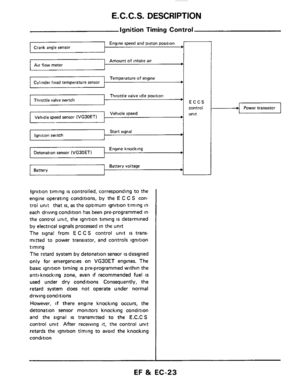
Ignition Timing Control
Engine speed and piston position Crank angle sensor
Amount of intake air Air flow meter
Temperature of engine Cylinder head temperature sensor
Throttle valve idle position
Vehicle speed Vehicle speed sensor (VG30ETl 1 I I
Start signal Ignition switch
Engine knocking Detonation sensor
Battery voltage Battery ~
Ignition
timing is controlled, corresponding to the
engine operating conditions, by the
E C C S con-
trol unit that
is, as the optimum ignition timing in
each driving condition has been pre-programmed in
the control unit, the ignition timing
IS determined
by electrical signals processed in the unit
The signal from
E C C S control unit is trans-
mitted to power transistor, and controls ignition
timing
The retard system by detonation sensor
is designed
only for emergencies on VG30ET engines. The
basic ignition timing
is pre-programmed within the
anti-knocking zone, even
if recommended fuel is
used under dry conditions Consequently, the
retard system does not operate under normal
driving conditions
However,
if there engine knocking occurs, the
detonation sensor monitors knocking condition
and the signal is transmitted to the E.C.C S
control unit After receiving it, the control unit
retards the ignition timing to avoid the knocking
condition
Power transistor
EF & EC-23
Page 24 of 79
E.C.C.S. DESCRIPTION
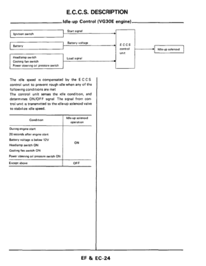
Battery voltage Battery
~-
Headlarnp switch Load signal
Cooling fan switch
Power steering oil pressure switch
Idle-up Control (VG30E engine)
Start signal Ignition switch
ECCS
control
unit
The idle speed is compensated by the E C C S
control unit to prevent rough idle when any of the
following conditions
are met
The control unit senses the idle condition, and
determines
ON/OFF signal The signal from con-
trol unit
is transmitted to the idle-uD solenoid valve
to stabilize idle speed.
Condition
During engine start
20 seconds after engine start
Battery voltage is below 12V
Headlarnp switch ON
Cooling fan switch ON
Power steering oil pressure switch ON
Except above
Idle-up solenoid
operation
ON
OFF
EF 8t EC-24

Start signal Ignition swi")