Page 12 of 79

AIR FLOW SYSTEM DESCRIPTION
TURBOCHARGER
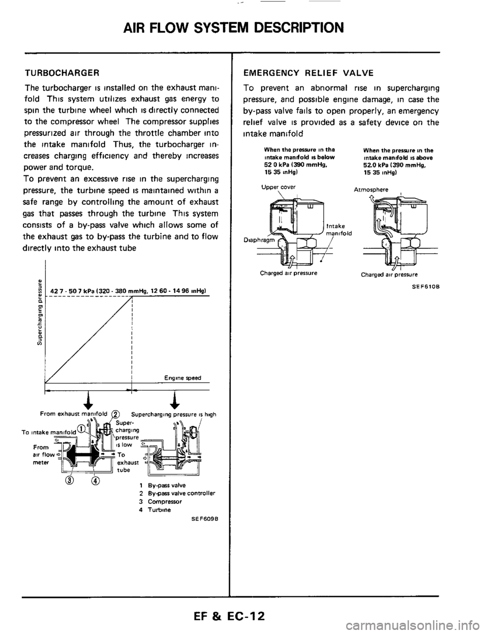
The turbocharger is installed on the exhaust mani-
fold This system utilizes exhaust gas energy to
spin the turbine wheel which
is directly connected
to the compressor wheel The compressor supplies
pressurized air through the throttle chamber into
the intake manifold Thus, the turbocharger in-
creases charging efficiency and thereby increases
power and torque.
To prevent an excessive rise in the supercharging
pressure, the turbine speed
is maintained within a
safe range by controlling the amount of exhaust
gas that passes through the turbine This system
consists of
a by-pass valve which allows some of
the exhaust gas to by-pass the turbine and to flow
directly into the exhaust tube
Engine speed
From b==iF exhausi man2fold 0 Superchargang pressure 41 hqh
To intake
From air flo meter
h
To intake
From air flo meter
2 Bygars valve controller
3 Compressor
4 Turbine
SEF609B
EMERGENCY RELIEF VALVE
To prevent an abnormal rise in supercharging
pressure, and possible engine damage, in case
the
by-pass valve fails to open properly, an emergency
relief valve
is provided as a safety device on the
intake manifold
When the prwre in the Intake mandold IS below 52 0 kPa 1390 mmHg. 15 35 inHgl
Upper cover
When the prerrura tn the intake mandold IS above 520 kPa 1390 mrnHg, 15 35 mHg)
Atmosphere
Charged air pressure Charged air pressure
SEF6lOB
EF & EC-12
Page 63 of 79

FUEL SYSTEM INSPECTION
Releasing Fuel Pressure
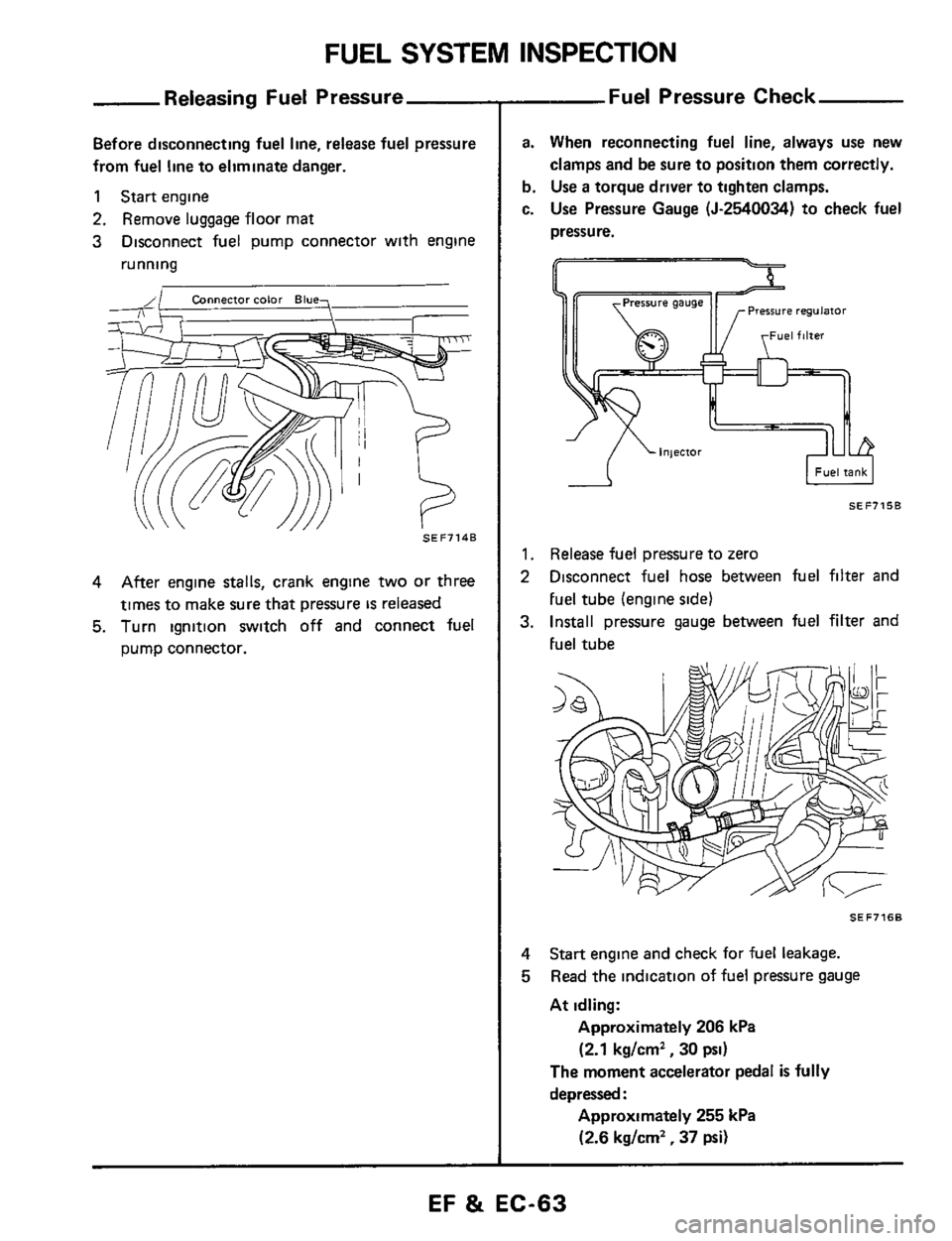
Before disconnecting fuel line, release fuel pressure
from fuel line to eliminate danger.
1 Start engine
2. Remove luggage floor mat
3 Disconnect fuel pump connector with engine
running
SEF7148
4 After engine stalls, crank engine two or three
times to make sure that pressure
IS released
5. Turn ignition switch off and connect fuel
pump connector.
--Fuel Pressure Check
a. When reconnecting fuel line, always use new
clamps and be sure to position them correctly.
b. Use a torque driver to tighten clamps.
c.
Use Pressure Gauge (5-2540034) to check fuel
pressure.
I Fuel tank I -A
SEF7158
1. Release fuel pressure to zero
2 Disconnect fuel hose between fuel filter and
Fuel tube (engine side1
3. Install pressure gauge between fuel filter and
Fuel tube
SEF7168
4
5
Start engine and check for fuel leakage.
Read the indication of fuel pressure gauge
At idling:
Approximately 206 kPa
(2.1 kg/cm2, 30 psi)
The moment accelerator pedal is fully
depressed
:
Approximately 255 kPa
(2.6 kg/cm2, 37 psi)
EF & EC-63
Page 79 of 79

SERVICE DATA AND SPECIFICATIONS (S.D.S.)
General Specifications
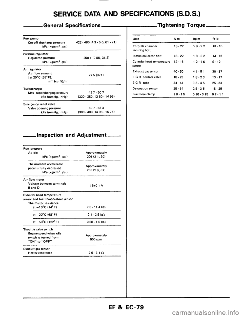
Fuel pump Cut-off discharge pressure 422 -490 I4 3 -5 0.61 .71)
kPa (kg/cm'. psi1
Pressure regulator Regulated pressure 250 1 (2 55.36 3) kPa Ikalcm'. Dsll
Air regulatoi
27 5 (971 I Air flow amount
[atZO'C (68OF)I m3 (cu ft)/hr ~~
Turbocharger
Max supercharging pressure 42 7 - 507
kPa (mmHa.
InHal (320-380.1260-1496)
Emergency relief valve Valve opening pressure 507 - 53 3
(380 -400.14 96 - 15 75) kPa (mmHg, InHg)
-inspection and Adjustment -
Fuel pressure
At idle Approximately
kPa (kg/cm', psi) 206 (2 1.30)
The moment accelerator
pedal IS fully depressed Approximately
255 (2 6.371 kPa (kglcm'. psi)
Air flow meter
Voltage between terminals
B and D 1 620 1 V
Cylinder head temperature
sensor and fuel temperature sensor Thermistor resistance
at-lO'C 114'F) 7 0- 11 4 kSl
at 20'C I68'Fl 21-29kSl
at 50°C Il22'FI 068- 1 0 kSl ~~~~
Throttle
valve switch Engine speed when idle
swmh
IS turned from
"ON" to "OFF"
Approximately
900 rpm
Exhaust gas sensor Heater resistance 26-31Sl
- Tightening Torque
-
U"lt Nm kwn ft-lb
Throttle chamber 18-22 18-22 13-16 securing bolt
Intakecollector bolt
18-22 18-22 13-16
Cylinder head temperature 12. 16 1 2.1 6 9.12 SeIlSOr
Exhaust gar senior 40.50 41-51 30-37
E G R control valve 18-23 18-23 13-17
E G H tube 34-44 35-45 25-33
Detonation sensor 25.34 25-35 18-25
Fuel hose clamp 10-15 010-015 07-1 1
EF %i EC-79