1984 NISSAN 300ZX clock
[x] Cancel search: clockPage 31 of 79
DIAGNOSTIC PROCEDURE
Driveabili
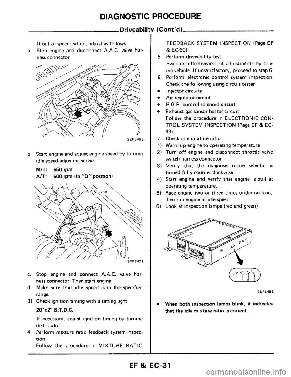
If out of specification, adjust as follows
ness connector
a Stop engine and disconnect A A C valve har-
SEF646B
b Start engine and adjust engine speed by turning
idle speed adjusting screw
M/T: 650 rpm
A/T. 600 rpm (in "D" position)
c. Stop engine and connect A.A.C. valve har-
ness connector Then
start engine
d Make sure that idle speed
is in the specified
range.
3) Check ignition timing with a timing light
ZO"r2" B.T.D.C.
If necessary, adjust ignition timing by turning
distributor
Perform mixture ratio feedback
system inspec-
tion Follow the procedure
in MIXTURE RATIO
4
(Cont'd)
FEEDBACK SYSTEM INSPECTION (Page EF
lk EC-60)
5 Perform driveability test
Evaluate effectiveness of adjustments by driv-
ing vehicle If unsatisfactory, proceed to step
6
6
Perform electronic control system inspection
Check the following using circuit tester
Injector circuits
Air regulator circuit
E G R control solenoid circuit
E xhaust gas sensor heater circuit
Follow the procedure in ELECTRONIC CON-
TROL SYSTEM INSPECTION (Page EF
& EC-
43)
7 Check idle mixture ratio
1) Warm up engine to operating temperature
2) Turn off engine and disconnect throttle valve
switch harness connector
3) Verify that the diagnosis mode selector is
turned fully counterclockwise
4) Start engine and verify that engine IS still at
operating temperature.
5) Race engine two or three times under no-load,
then run engine
at idle speed
6) Look at inspection lamps (red and green)
SEF648B
When both inspection lamps blink, it indicates
that the idle mixture ratio IS correct.
EF & EC-31
Page 35 of 79
SELF-DIAGNOSIS
Self-diagni
The self-diagnostic system determines malfunctions
of signal systems such as sensors, actuators, and
wire harnesses based on the status of the input
signals received by the
E C C S control unit
A malfunction is displayed by both the red and
green
L E D s (Light Emitting Diodes).
Basically, self-diagnosis
is always performed when
the power
is furnished to the E C C S control
unit The self-diagnosis results
are retained in the
memory chip of the
E C C S control unit and are
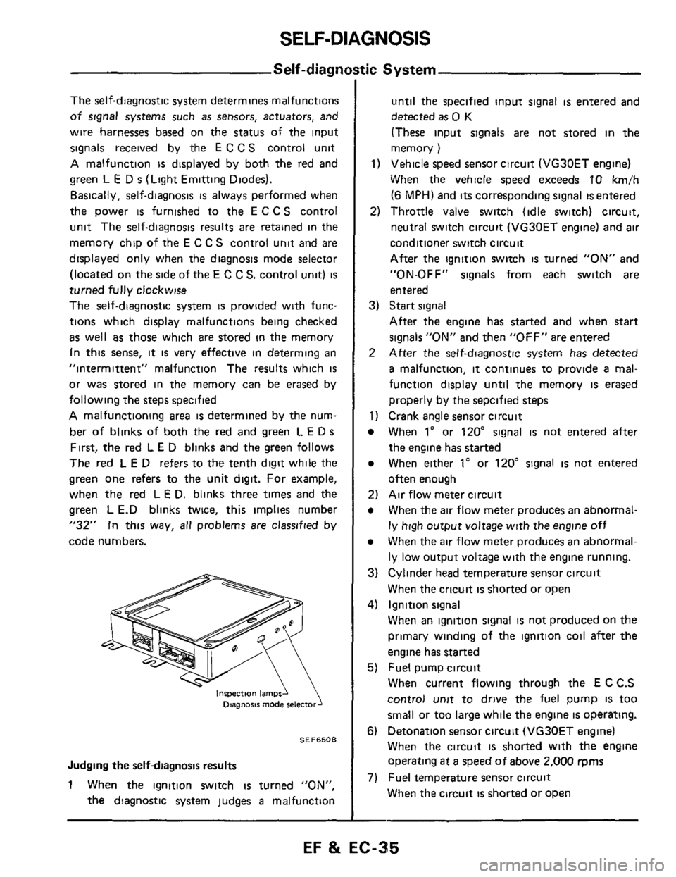
displayed only when the diagnosis mode selector
(located on
the side of the E C C S. control unit) is
turned fully clockwise
The self-diagnostic system
is provided with func-
tions which display malfunctions being checked
as well as those which are stored in the memory
In
this sense, it is very effective in determing an
"intermittent" malfunction The results which
is
or was stored in the memory can be erased by
following the steps specified
A malfunctioning area is determined by the num-
ber of blinks of both the
red and green L E D s
First, the red L E D blinks and the green follows
The red L E D refers to the tenth digit while the
green
one refers to the unit digit. For example,
when the red L
E D. blinks three times and the
green
L E.D blinks twice, this implies number
"32" In this way, all problems are classified by
code numbers.
inspection lamps1 Diagnosis mode
SEF6508
Judging the selfdiagnosis results
1 When the ignition switch is turned "ON",
the diagnostic system judges
a malfunction
tic System
until the specified input signal is entered and
detected
as 0 K
(These input signals are not stored in the
memory
)
1) Vehicle speed sensor circuit (VG30ET engine)
When the vehicle speed exceeds
10 km/h
(6 MPH) and its corresponding signal is entered
2) Throttle valve switch (idle switch) circuit,
neutral switch circuit (VG30ET engine) and
air
conditioner switch circuit
After the ignition switch
is turned "ON" and
"ON-OFF"
signals from each switch are
entered
3) Start signal
After the engine has started and when start
signals "ON" and then "OFF" are entered
2 After the self-diagnostic system has detected
a malfunction, it continues to provide a mal-
function display until the memory
is erased
properly by the sepcified steps
1) Crank angle sensor circuit
When 1" or 120" signal is not entered after
the engine has started
When either 1" or 120" signal is not entered
often enough
2) Air flow meter circuit
When the air flow meter produces an abnormal-
ly high output voltage with the engine off
When the air flow meter produces an abnormal-
ly low output voltage with the engine running.
3) Cylinder head temperature sensor circuit
When the cricuit
is shorted or open
4) Ignition signal
When an ignition signal
is not produced on the
primary winding of the ignition coil after
the
engine has started
5) Fuel pump circuit
When current flowing through the E
C C.S
control
unit to drive the fuel pump IS too
small or too large while the engine
is operating.
6) Detonation sensor circuit (VG30ET engine)
When the circuit
is shorted with the engine
operating
at a speed of above 2,000 rpms
When the circuit is shorted or open
7) Fuel temperature sensor circuit
EF & EC-35
Page 37 of 79
SELF-DIAGNOSIS
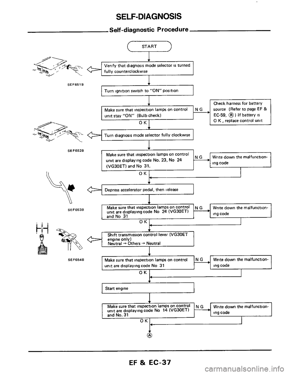
Self-diagnostic Procedure
fully counterclockwise -,
SEF651B
Turn Ignition switch to "ON" Poslflon1
Check harness for battery
source (Refer to page
EF &
EC-59, 8) If battery is
0 K , replace control unit
unit stay "ON" (Bulb check)
Turn diagnosis mode selector fully clockwise
Write down the malfunction- unit are displaying code No. 23, No 24
(VG30ET) and No 31.
I
SEF653B
ing code
SEF654B
unit are displaying code No 31
OK
Start engine 41
Make sure that N G Write down the malfunction-
unit are displaying code No 14 (VG30ET)
and No. 31 ing code
OK1
EF & EC-37
Page 38 of 79
SELF-DIAGNOSIS
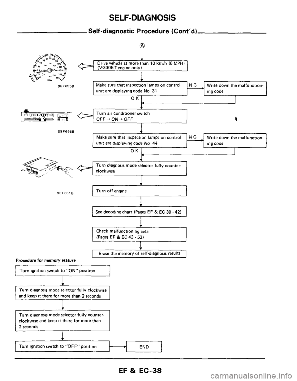
Self-diagnostic Procedure (Cont'd)
SEF655B
SEF6568
SEF651B
Drive vehde ax more than 10 kmlh (6 MPrll
(VG30ET eng.ne onov)
I 4
Make sure that inspection lamps on control
unit are displaying code
No 31
Write down the malfunction-
ing code
OK
Turn air conditioner switch
4
Write down the malfunction-
ing code
unit are displaying code No 44
OK
Turn diagnosis mode selector fully counter-
clockwise
4
Turn off engine 1
] See decoding chart (Pages EF & EC 39 - 42) I
(Pages EF & EC 43 - 53)
v
Erase the memorv of selfdiaanosis results
Procedure for memory erasure
Turn ignition switch to "ON" position
Turn diagnosis mode selector fully clockwise
and keep
it there for more than 2 seconds
Turn diagnosis mode selector fully counter-
clockwise and keep
it there for more than
2 seconds
Turn ignition switch to "OFF" position
EF & EC-38
Page 60 of 79
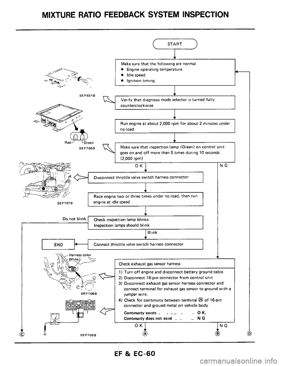
MIXTURE RATIO FEEDBACK SYSTEM INSPECTION
SEF707B
START
-
Make sure that the following are normal
engine at idle speed
SEF651B
SEF70BB
een
jumper wire.
connector and ground metal
on vehicle body
Continuity exists
. . .. .. . . 0 K.
Continuity does not exist . . .. N G
4) Check for continuity between terminal @ of 16-pin
SEF706B
t
Verify that diagnosis mode selector is turned fully
cou nterclockwise
1
Run engine at about 2,000 rpm for about 2 minutes under
no-load
I
4
Make sure that inspection lamp (Green) on control unit
aoes
on and off more than 5 times durinq 10 seconds
I i2~000 rom) .. .~,. ~ ~
OK
Disconnect throttle valve switch harness connector
1
I Race engine two or three times under no-load, then run I
I JG
1
SEF709B
EF 81 EC-60