1984 NISSAN 300ZX Air flow meter
[x] Cancel search: Air flow meterPage 2 of 79
PRECAUTIONS
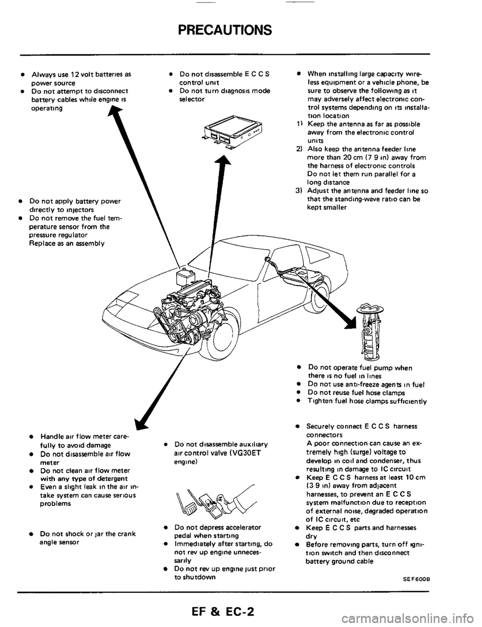
Always use 12 volt batteries as * Do not disassemble E C C S When installing large capacity wire-
Do not attempt to disconnect Do not turn diagnosis mode sure to obsetve the following as it power source
battery cables while engine
IS
control unit
selector less equipment or a vehicle phone, be
may adversely affect electronic con-
operating
Do not apply battery power
directly to injectors
Do not remove the fuel tem-
perature sensor from
the T
pressure regulator
Replace as an assembly
trol systems depending on its installa-
tion location
1) Keep the antenna as far as possible
away from the electronic control
units
2) Also keep the antenna feeder line
more than
20 cm (7 9 in) away from
the harness of electronic controls
Do not let them run parallel for a
long distance
3) Adjust the antenna and feeder line so
that the standing-wave ratio can be
keot smaller
J
Handle air flow meter care-
fully to avoid damage * Do not disassemble auxiliary
Do not disassemble air flow air control valve (VG30ET
meter engine)
Do not clean air flow meter
with any type of detergent
0 Even a slight leak in the air in- /
&&%$$?&
take system can cause serious
problems
Do not depress accelerator Do not shock or jar the crank
angle sensor
Immediately after starting, do
pedal when starting
not rev
up engine unneces-
sarily
Do not rev up engine just prioi
to shutdown
Do not operate fuel pump when
there is no fuel in lines Do not use anti-freeze agents in fuel
0 Do not reuse fuel hose clamps
0 Tighten fuel hose clamps sufficiently
Securely connect E C C S harness
connectors
A poor connection can cause an ex-
tremely
high (surge) voltage to
develop in coil and condenser, thus
resulting in damage to IC circuit
Keep
E C C S harness at least 10 cm
(3 9 in) away from adjacent
harnesses, to prevent an
E C C S
system malfunction due to reception
of external noise, degraded operation
of
IC circuit. etc
Keep E C C S parts and harnesses
Before removing parts, turn off igni-
tion switch and then disconnect
battery ground cable dry
SEF6008
EF & EC-2
Page 7 of 79
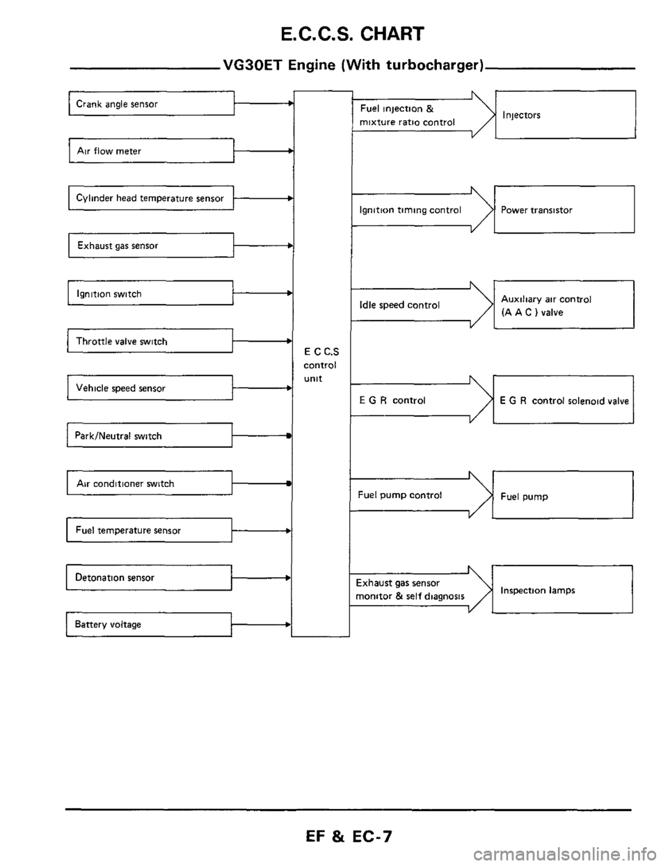
E. C. C.S. CHART
VG30ET Engine (With turbocharger)
Air flow meter c
Cylinder head temperature sensor b
b
Ignition switch b
Throttle valve switch I b
b
Park/Neutral switch
Air conditioner switch I
b
E C C.S
control
unit
b
Injectors Fuel injection &
mixture ratio control
--I
Ignition timing control Power transistor
-dI Auxiliary air control
(A A
C ) valve Idle speed control
I YL
E G R control E G R control solenoid valve
Fuel pump control Fuel pump
Inspection lamps ixhaust gas sensor
nonitor
& self diagnosis I
EF & EC-7
Page 12 of 79
AIR FLOW SYSTEM DESCRIPTION
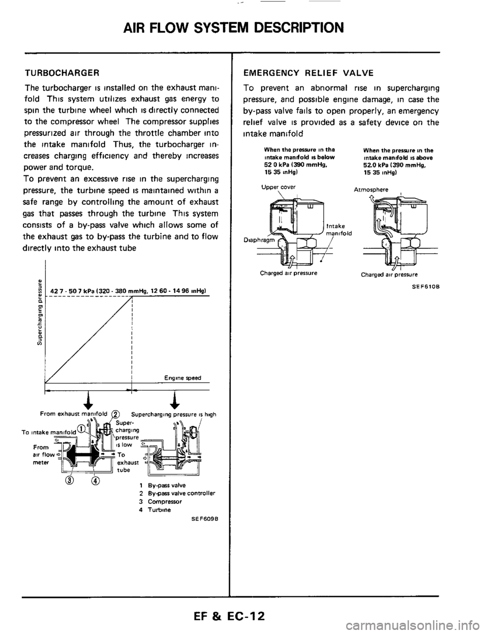
TURBOCHARGER
The turbocharger is installed on the exhaust mani-
fold This system utilizes exhaust gas energy to
spin the turbine wheel which
is directly connected
to the compressor wheel The compressor supplies
pressurized air through the throttle chamber into
the intake manifold Thus, the turbocharger in-
creases charging efficiency and thereby increases
power and torque.
To prevent an excessive rise in the supercharging
pressure, the turbine speed
is maintained within a
safe range by controlling the amount of exhaust
gas that passes through the turbine This system
consists of
a by-pass valve which allows some of
the exhaust gas to by-pass the turbine and to flow
directly into the exhaust tube
Engine speed
From b==iF exhausi man2fold 0 Superchargang pressure 41 hqh
To intake
From air flo meter
h
To intake
From air flo meter
2 Bygars valve controller
3 Compressor
4 Turbine
SEF609B
EMERGENCY RELIEF VALVE
To prevent an abnormal rise in supercharging
pressure, and possible engine damage, in case
the
by-pass valve fails to open properly, an emergency
relief valve
is provided as a safety device on the
intake manifold
When the prwre in the Intake mandold IS below 52 0 kPa 1390 mmHg. 15 35 inHgl
Upper cover
When the prerrura tn the intake mandold IS above 520 kPa 1390 mrnHg, 15 35 mHg)
Atmosphere
Charged air pressure Charged air pressure
SEF6lOB
EF & EC-12
Page 14 of 79
E.C.C.S. DESCRIPTION
E.C.C.S. Components (Cont'd)
A
Air flow meter 0.
C
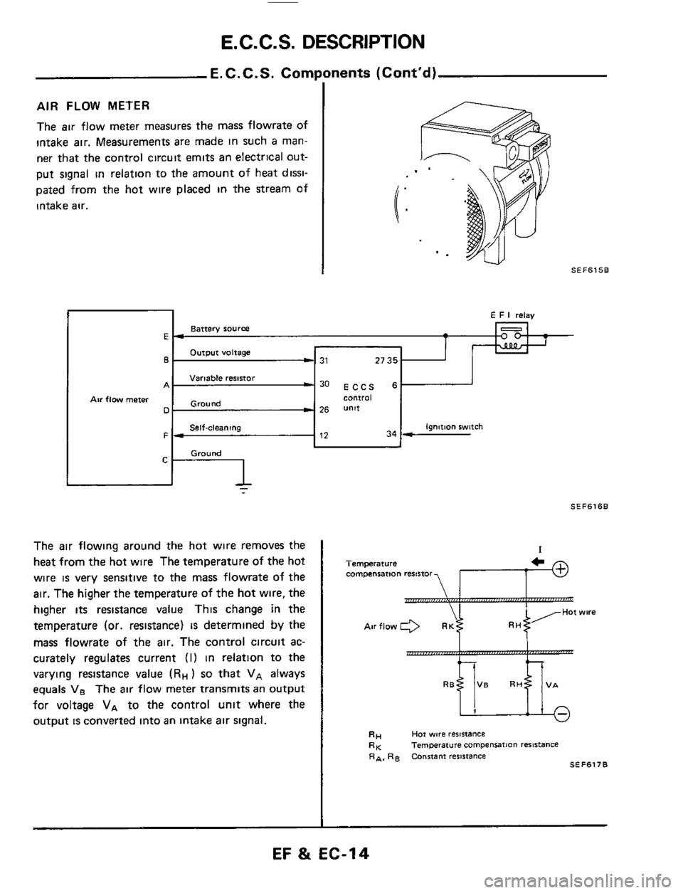
AIR FLOW METER
The air flow meter measures the mass flowrate of
intake air. Measurements are made in such
a man-
ner
that the control circuit emits an electrical out-
put signal
in relation to the amount of heat dissi-
pated from the hot wire placed
in the stream of
intake
air.
E F I relay
Battery source
Output voltage
Variable resistor
25 unit Ground
Self-cleaning ignition switch
Ground
El -
-
6- 31 27 35 1
w30 ECCS 6 comroi
F- 12 34 -
-
I SEF615B
SEFSlSB
The air flowing around the hot wire removes the
heat from
the hot wire The temperature of the hot
wire
is very sensitive to the mass flowrate of the
air.
The higher the temperature of the hot wire, the
higher
its resistance value This change in the
temperature (or. resistance)
IS determined by the
mass flowrate of the air. The control circuit
ac-
curately regulates current (I) in relation to the
varying resistance value
(RH) so that VA always
equals VB The air flow meter transmits an output
for voltage
VA to the control unit where the
output
is convened into an intake air signal.
I
Temperature compensation resistor
twire
Hot wore reststance
Temperature campenration resistance RA. RB Constant reSiiIanCe
RH RK
SEFS17B
I
EF & EC-14
Page 20 of 79
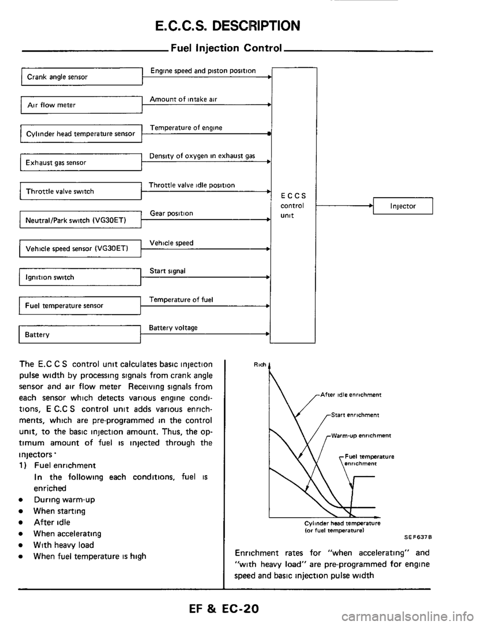
E.C.C.S. DESCRIPTION
Fuel Injection Control
Temperature of engine Cylinder head temperature sensor
Density of oxygen in exhaust gas Exhaust gas sensor
Throttle valve idle position ' Throttle valve switch
Engine speed and piston position
Amount of intake air Air flow meter
ECCS
I I
I
control
Gear position unit NeutraVPark switch (VG30ET) I I
Vehicle speed
Start signal
Temperature of fuel
Battery voltage Battery
The E.C C S control unit calculates basic injection
pulse
width by processing signals from crank angle
sensor and air flow meter Receiving signals from
each sensor which detects various engine condi-
tions,
E C.C S control unit adds various enrich-
ments, which are pre-programmed
in the control
unit, to the basic injection amount. Thus, the op-
timum amount of fuel is injected through the
injectors.
1 ) Fuel enrichment
In the following each conditions, fuel is
enriched
e During warm-up
When starting
After idle
e When accelerating
e With heavy load
e When fuel temperature is high
.I Injector
Rlch
' \/ .-Warm-u~ enrichment
Cylmder head temperature (or fuel temperature1 SE F637 0
Enrichment rates for "when accelerating" and
"with heavy load" are pre-programmed for engine
speed and basic injection pulse
width
EF & EC-20
Page 23 of 79
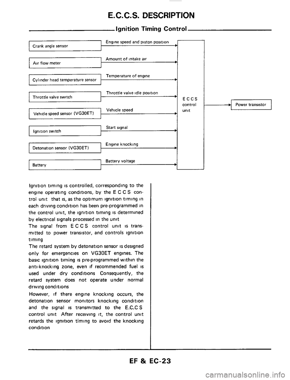
E. C. C. S. DESCRIPTION
Ignition Timing Control
Engine speed and piston position Crank angle sensor
Amount of intake air Air flow meter
Temperature of engine Cylinder head temperature sensor
Throttle valve idle position
Vehicle speed Vehicle speed sensor (VG30ETl 1 I I
Start signal Ignition switch
Engine knocking Detonation sensor
Battery voltage Battery ~
Ignition
timing is controlled, corresponding to the
engine operating conditions, by the
E C C S con-
trol unit that
is, as the optimum ignition timing in
each driving condition has been pre-programmed in
the control unit, the ignition timing
IS determined
by electrical signals processed in the unit
The signal from
E C C S control unit is trans-
mitted to power transistor, and controls ignition
timing
The retard system by detonation sensor
is designed
only for emergencies on VG30ET engines. The
basic ignition timing
is pre-programmed within the
anti-knocking zone, even
if recommended fuel is
used under dry conditions Consequently, the
retard system does not operate under normal
driving conditions
However,
if there engine knocking occurs, the
detonation sensor monitors knocking condition
and the signal is transmitted to the E.C.C S
control unit After receiving it, the control unit
retards the ignition timing to avoid the knocking
condition
Power transistor
EF & EC-23
Page 29 of 79
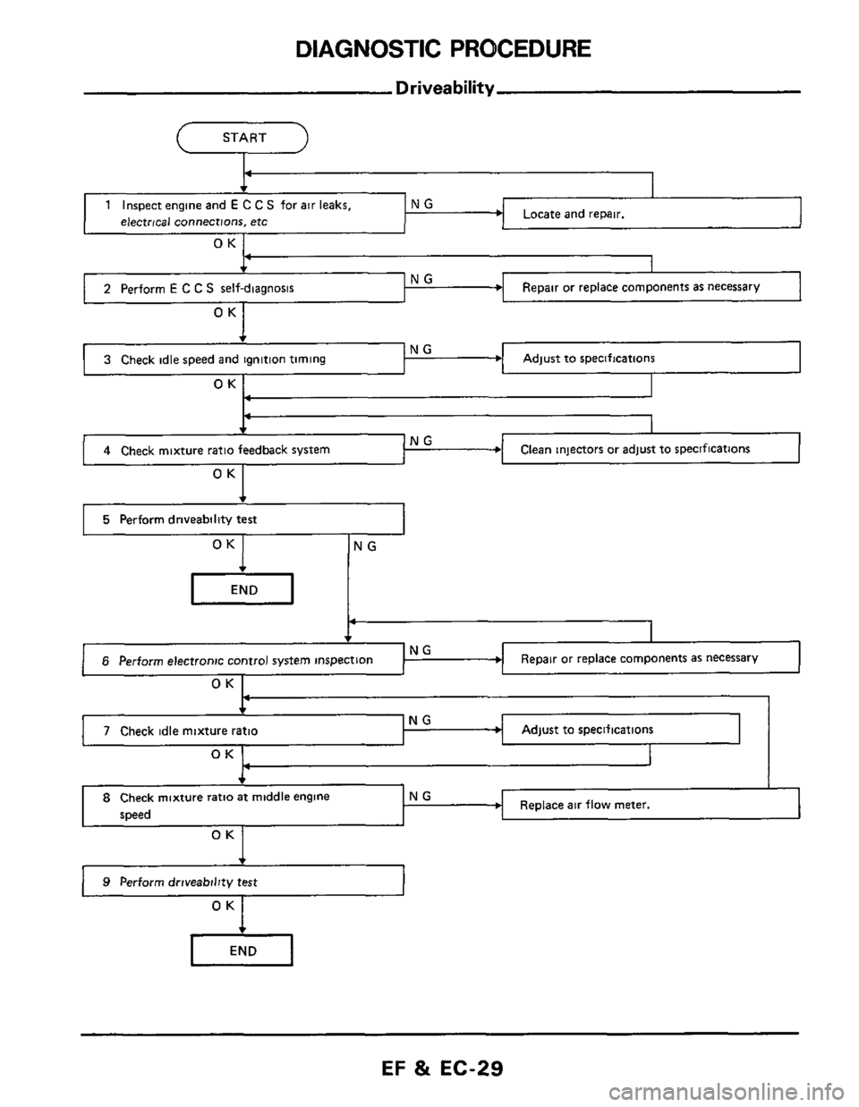
DIAGNOSTIC PROCEDURE
b NG 3 Check idle speed and ignition timing
Driveability
(--- START -l
Adjust to specifications
4 Check mixture ratio feedback system Clean injectors or adjust to specifications
I 5 Perform driveability test I
OK NG
Repair or replace components as necessary
P
6 Perform electronic control system inspection
OK I
Adjust to specifications
OK 1 I
NG 4-
7 Check idle mixture ratio
, I
I
Replace air flow meter. 8 Check mixture ratio at middle engine NG
speed
OK
) 9 Perform driveability test
EF & EC-29
Page 32 of 79
DIAGNOSTIC PROCEDURE
Driveability (Cont'd)
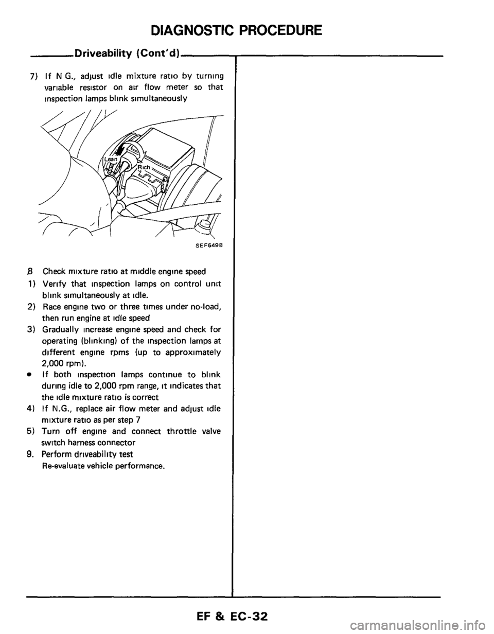
7) If N G., adjust idle mixture ratio by turning
variable resistor on
air flow meter so that
inspection lamps blink simultaneously
SEF649B
B Check mixture ratio at middle engine speed
1) Verify that inspection lamps on control unit
blink simultaneously at idle.
2) Race engine two or three times under no-load,
then run engine
at idle speed
3) Gradually increase engine speed and check for
operating (blinking)
of the inspection lamps at
different engine rpms (up to approximately
2,000 rprn).
If both inspection lamps continue to blink
during idle to
2,000 rpm range, it indicates that
the idle mixture ratio is correct
4) If N.G., replace air flow meter and adjust idle
mixture ratio
as per step 7
5) Turn off engine and connect throttle valve
switch harness connector
9. Perform driveability test
Reevaluate vehicle performance.
EF %t EC-32