Page 36 of 79
SELF-DIAGNOSIS
-Self-diagnostic System (Cont'd)-
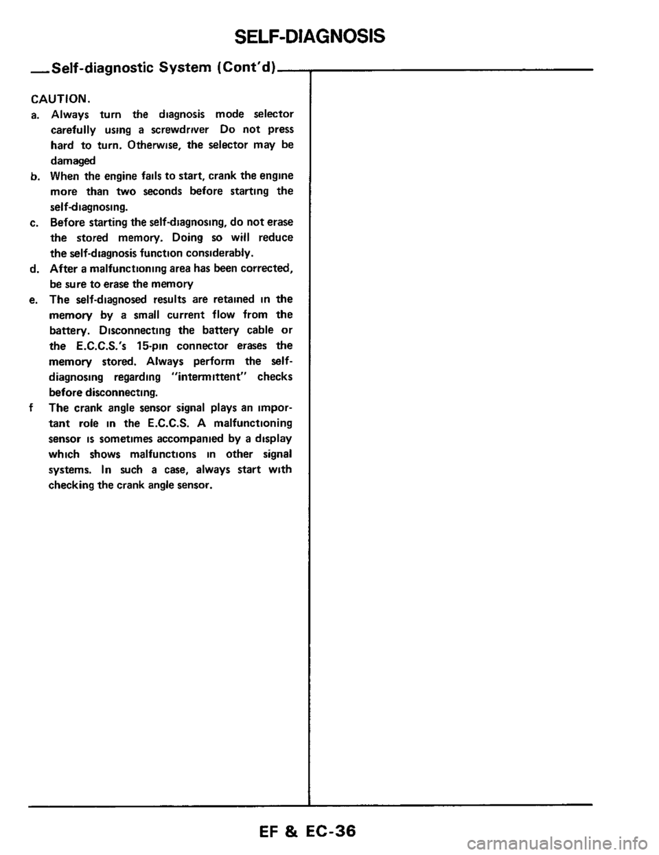
CAUTION.
a. Always turn the diagnosis mode selector
carefully using
a screwdriver Do not press
hard to turn. Otherwise, the selector may be
damaged
b. When the engine fails to start, crank the engine
more
than two seconds before starting the
self-diagnosing.
c. Before starting the self-diagnosing, do not erase
the stored memory. Doing
so will reduce
the self-diagnosis function considerably.
d. After a malfunctioning area has been corrected,
be sure to erase the memory
e. The self-diagnosed results are retained in the
memory by a small current flow from the
battery. Disconnecting the battery cable
or
the E.C.C.S.'s 15-pin connector erases the
memory stored. Always perform the
self-
diagnosing regarding "intermittent" checks
before disconnecting.
The crank
angle sensor signal plays an impor-
tant role in the E.C.C.S. A malfunctioning
sensor
is sometimes accompanied by a display
which shows malfunctions in other signal
systems.
In such a case, always start with
checking the crank angle sensor.
f
EF & EC-36
Page 38 of 79
SELF-DIAGNOSIS
Self-diagnostic Procedure (Cont'd)
SEF655B
SEF6568
SEF651B
Drive vehde ax more than 10 kmlh (6 MPrll
(VG30ET eng.ne onov)
I 4
Make sure that inspection lamps on control
unit are displaying code
No 31
Write down the malfunction-
ing code
OK
Turn air conditioner switch
4
Write down the malfunction-
ing code
unit are displaying code No 44
OK
Turn diagnosis mode selector fully counter-
clockwise
4
Turn off engine 1
] See decoding chart (Pages EF & EC 39 - 42) I
(Pages EF & EC 43 - 53)
v
Erase the memorv of selfdiaanosis results
Procedure for memory erasure
Turn ignition switch to "ON" position
Turn diagnosis mode selector fully clockwise
and keep
it there for more than 2 seconds
Turn diagnosis mode selector fully counter-
clockwise and keep
it there for more than
2 seconds
Turn ignition switch to "OFF" position
EF & EC-38
Page 60 of 79
MIXTURE RATIO FEEDBACK SYSTEM INSPECTION
SEF707B
START
-
Make sure that the following are normal
engine at idle speed
SEF651B
SEF70BB
een
jumper wire.
connector and ground metal
on vehicle body
Continuity exists
. . .. .. . . 0 K.
Continuity does not exist . . .. N G
4) Check for continuity between terminal @ of 16-pin
SEF706B
t
Verify that diagnosis mode selector is turned fully
cou nterclockwise
1
Run engine at about 2,000 rpm for about 2 minutes under
no-load
I
4
Make sure that inspection lamp (Green) on control unit
aoes
on and off more than 5 times durinq 10 seconds
I i2~000 rom) .. .~,. ~ ~
OK
Disconnect throttle valve switch harness connector
1
I Race engine two or three times under no-load, then run I
I JG
1
SEF709B
EF 81 EC-60