Page 35 of 79
SELF-DIAGNOSIS
Self-diagni
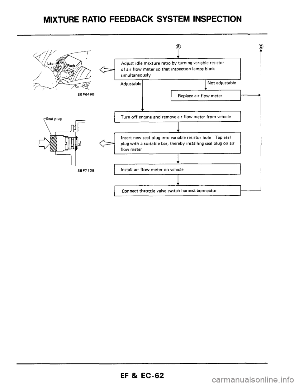
The self-diagnostic system determines malfunctions
of signal systems such as sensors, actuators, and
wire harnesses based on the status of the input
signals received by the
E C C S control unit
A malfunction is displayed by both the red and
green
L E D s (Light Emitting Diodes).
Basically, self-diagnosis
is always performed when
the power
is furnished to the E C C S control
unit The self-diagnosis results
are retained in the
memory chip of the
E C C S control unit and are
displayed only when the diagnosis mode selector
(located on
the side of the E C C S. control unit) is
turned fully clockwise
The self-diagnostic system
is provided with func-
tions which display malfunctions being checked
as well as those which are stored in the memory
In
this sense, it is very effective in determing an
"intermittent" malfunction The results which
is
or was stored in the memory can be erased by
following the steps specified
A malfunctioning area is determined by the num-
ber of blinks of both the
red and green L E D s
First, the red L E D blinks and the green follows
The red L E D refers to the tenth digit while the
green
one refers to the unit digit. For example,
when the red L
E D. blinks three times and the
green
L E.D blinks twice, this implies number
"32" In this way, all problems are classified by
code numbers.
inspection lamps1 Diagnosis mode
SEF6508
Judging the selfdiagnosis results
1 When the ignition switch is turned "ON",
the diagnostic system judges
a malfunction
tic System
until the specified input signal is entered and
detected
as 0 K
(These input signals are not stored in the
memory
)
1) Vehicle speed sensor circuit (VG30ET engine)
When the vehicle speed exceeds
10 km/h
(6 MPH) and its corresponding signal is entered
2) Throttle valve switch (idle switch) circuit,
neutral switch circuit (VG30ET engine) and
air
conditioner switch circuit
After the ignition switch
is turned "ON" and
"ON-OFF"
signals from each switch are
entered
3) Start signal
After the engine has started and when start
signals "ON" and then "OFF" are entered
2 After the self-diagnostic system has detected
a malfunction, it continues to provide a mal-
function display until the memory
is erased
properly by the sepcified steps
1) Crank angle sensor circuit
When 1" or 120" signal is not entered after
the engine has started
When either 1" or 120" signal is not entered
often enough
2) Air flow meter circuit
When the air flow meter produces an abnormal-
ly high output voltage with the engine off
When the air flow meter produces an abnormal-
ly low output voltage with the engine running.
3) Cylinder head temperature sensor circuit
When the cricuit
is shorted or open
4) Ignition signal
When an ignition signal
is not produced on the
primary winding of the ignition coil after
the
engine has started
5) Fuel pump circuit
When current flowing through the E
C C.S
control
unit to drive the fuel pump IS too
small or too large while the engine
is operating.
6) Detonation sensor circuit (VG30ET engine)
When the circuit
is shorted with the engine
operating
at a speed of above 2,000 rpms
When the circuit is shorted or open
7) Fuel temperature sensor circuit
EF & EC-35
Page 39 of 79
SELF-DIAGNOSIS
Decoding Chart
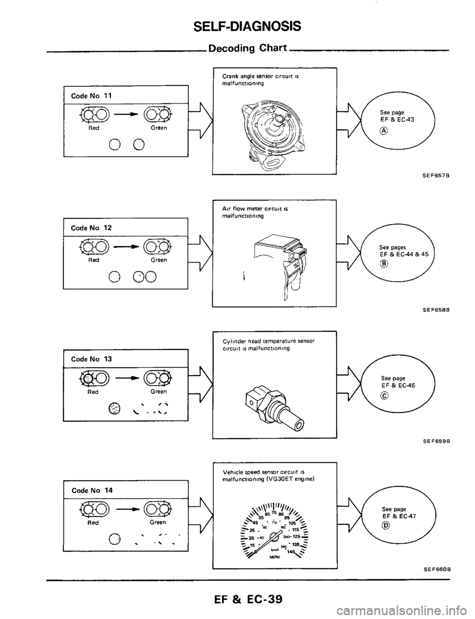
I Code No 11
I ked Green
00
1 CodeNo 12
I 'Red Green
0 00
Crank angle sensor circuit IS malfunctioning
Air flow meter circuit IS
malfunctioning 1
See page
EF & EC43
SEF6578
EF & EC44 & 45
1
SEF658B II
I CodeNo 13 I
Cylinder head temperature sensor clrcuit IS malfunctioning
See page EF & EC-46
SEF659B II
Vehtcle speed sensor circuit IS malfunctioning (VG30ET engine)
See page
EF & EC47
Id SEF660B
EF & EC-39
Page 44 of 79
ELECTRONIC CONTROL SYSTEM INSPECTION
VG -
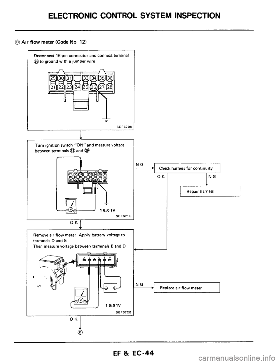
@Air flow meter (Code No 12)
Check harness for continuity
Disconnect 16pin connector and connect terminal
@to ground with
a jumper wire
NG -
Turn ignition switch ”ON” and measure voltage
between terminals @and
@I
Replace air flow meter
1 6tO 1V
SEF671B
O “I
Remove air flow meter Apply battery voltage to
terminals
D and E
Then measure voltage between terminals Band D
SEF672B
I
OK
7
IN
Repair harness
OK
@
EF 81 EC-44
Page 45 of 79
ELECTRONIC CONTROL SYSTEM INSPECTION
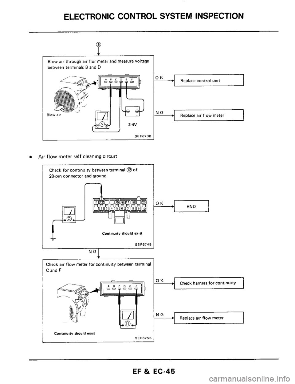
+I Replace control unit
t +I Replace air flow meter
Blow air through air flor meter and measure voltage
between terminals
B and D
Blo
I
I SEF6730
Air flow meter self cleaning circuit
Check for continuity between terminal @of
20-pin connector and ground
I
n
Contwny should extR
SEF6748
___~
Check air flow meter for continuity between terminal
C and F
Check harness for continuitv
Replace air flow meter
I Continuity should exis
SEF6750
EF & EC-45
Page 61 of 79
MIXTURE RATIO FEEDBACK SYSTEM INSPECTION
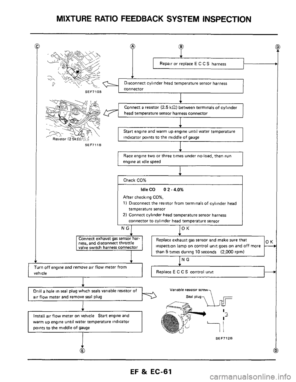
Repair or replace E C C S harness
SEF71OB
SEF7118
f
Connect a resistor (2.5 kS2) between terminals of cylinder
head temperature sensor harness connector
I
Start engine and warm up engine until water temperature
indicator points to the middle
of gauge
Race engine two or three times under no-load. then run
engine
at idle speed
After checking CO%,
1) Disconnect the resistor from terminals of cylinder head
temperature sensor
2) Connect cylinder head temperature sensor harness
connector to cylinder head temperature sensor
ness, and disconnect throttle inspection lamp on control unit goes on and off more
I
Turn off engine and remove air flow meter from
vehicle ~~
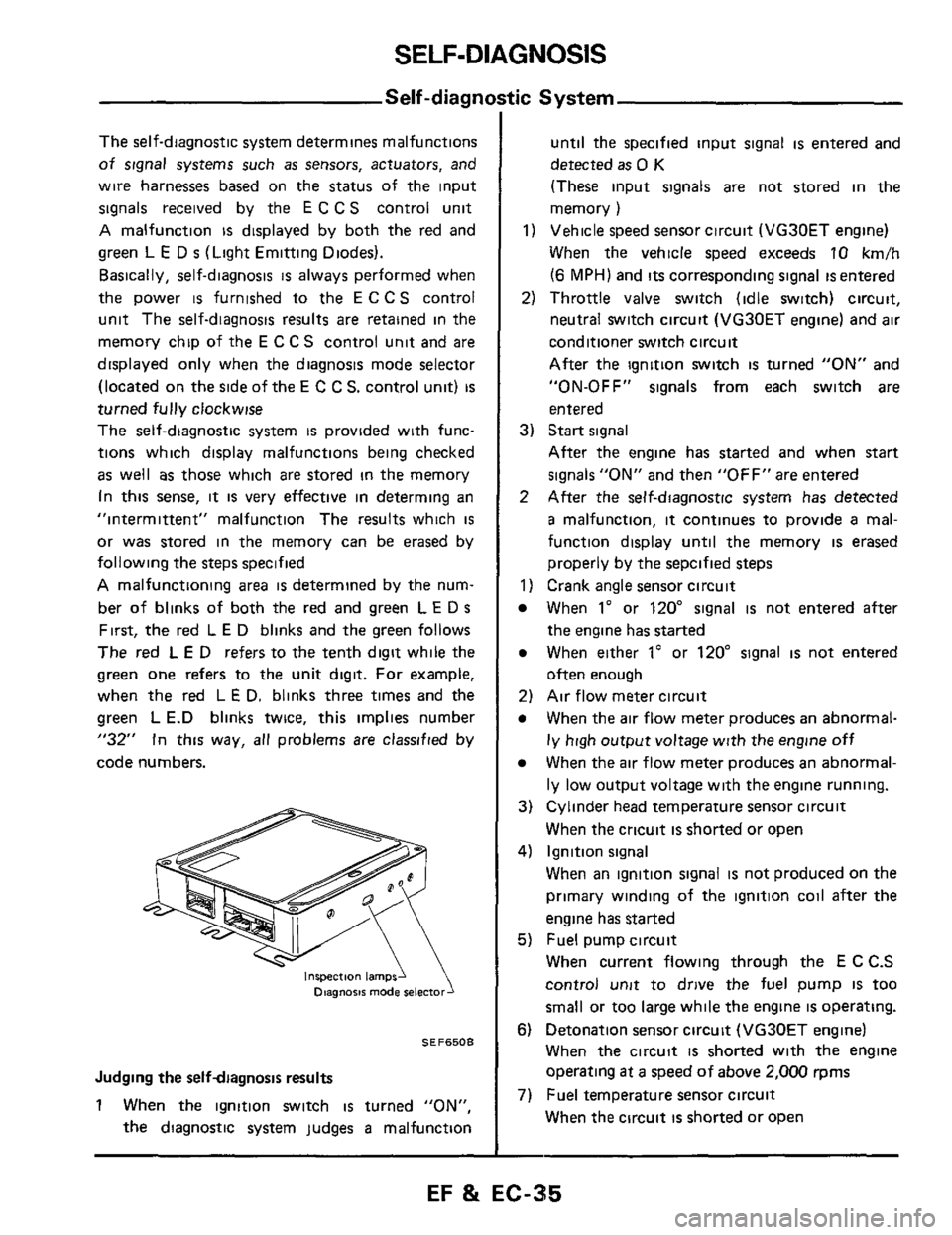
Drill a hole
in seal plug which seals variable resistor of
air flow meter and remove seal plug
warm up engine until water temperature indicator
Varrable resistor scmw
SEF7128
Page 62 of 79
MIXTURE RATIO FEEDBACK SYSTEM INSPECTION
SEF7138
SEF649B
Install air flow meter on vehicle
P
of air flow meter so that inspection lamps blink
Not adjustable Adjustable
Replace air flow meter
Turn off engine and remove air flow meter from vehicle
1
Insert new seal plug into variable resistor hole Tap seal
plug with a suitable bar, thereby installing seal plug on air
flow meter
1 Connect throttle valve switch harness connector I---
EF & EC-62
Page 79 of 79
SERVICE DATA AND SPECIFICATIONS (S.D.S.)
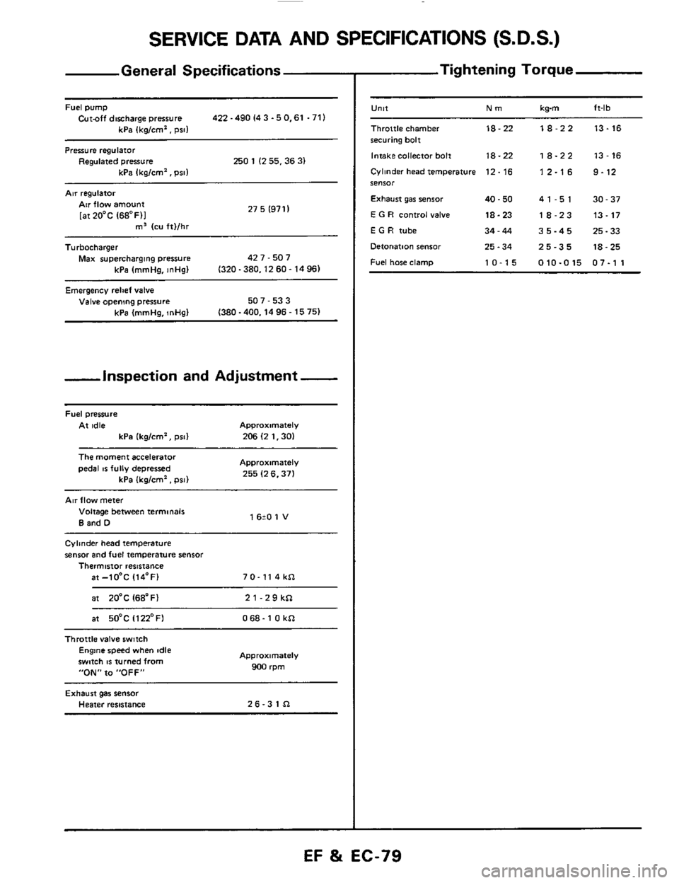
General Specifications
Fuel pump Cut-off discharge pressure 422 -490 I4 3 -5 0.61 .71)
kPa (kg/cm'. psi1
Pressure regulator Regulated pressure 250 1 (2 55.36 3) kPa Ikalcm'. Dsll
Air regulatoi
27 5 (971 I Air flow amount
[atZO'C (68OF)I m3 (cu ft)/hr ~~
Turbocharger
Max supercharging pressure 42 7 - 507
kPa (mmHa.
InHal (320-380.1260-1496)
Emergency relief valve Valve opening pressure 507 - 53 3
(380 -400.14 96 - 15 75) kPa (mmHg, InHg)
-inspection and Adjustment -
Fuel pressure
At idle Approximately
kPa (kg/cm', psi) 206 (2 1.30)
The moment accelerator
pedal IS fully depressed Approximately
255 (2 6.371 kPa (kglcm'. psi)
Air flow meter
Voltage between terminals
B and D 1 620 1 V
Cylinder head temperature
sensor and fuel temperature sensor Thermistor resistance
at-lO'C 114'F) 7 0- 11 4 kSl
at 20'C I68'Fl 21-29kSl
at 50°C Il22'FI 068- 1 0 kSl ~~~~
Throttle
valve switch Engine speed when idle
swmh
IS turned from
"ON" to "OFF"
Approximately
900 rpm
Exhaust gas sensor Heater resistance 26-31Sl
- Tightening Torque
-
U"lt Nm kwn ft-lb
Throttle chamber 18-22 18-22 13-16 securing bolt
Intakecollector bolt
18-22 18-22 13-16
Cylinder head temperature 12. 16 1 2.1 6 9.12 SeIlSOr
Exhaust gar senior 40.50 41-51 30-37
E G R control valve 18-23 18-23 13-17
E G H tube 34-44 35-45 25-33
Detonation sensor 25.34 25-35 18-25
Fuel hose clamp 10-15 010-015 07-1 1
EF %i EC-79