Page 6 of 79
E.C.C.S. CHART
Exhaust gas sensor t
b
Throttle valve switch -b
VG30E Engine (Without turbocharger)
ECCS
control
unit
Crank angle sensor
%el pump control Fuel pump
Air conditioner switch 1 t
Battery voltage
- I
Injectors Fuel injection &
mixture ratio control
VI 1
1
Ignition timing control Power transistor
Idle-up control Idle-up solenoid valve
E G R control E G R control solenoid valve
-1 I
Inspection lamps ixhaust gas sensor
nonitor
& self-diamosis
EF & EC-6
Page 7 of 79
E. C. C.S. CHART
VG30ET Engine (With turbocharger)
Air flow meter c
Cylinder head temperature sensor b
b
Ignition switch b
Throttle valve switch I b
b
Park/Neutral switch
Air conditioner switch I
b
E C C.S
control
unit
b
Injectors Fuel injection &
mixture ratio control
--I
Ignition timing control Power transistor
-dI Auxiliary air control
(A A
C ) valve Idle speed control
I YL
E G R control E G R control solenoid valve
Fuel pump control Fuel pump
Inspection lamps ixhaust gas sensor
nonitor
& self diagnosis I
EF & EC-7
Page 15 of 79
E. C. C. S. DESCRIPTION
E.C.C.S. Corn1
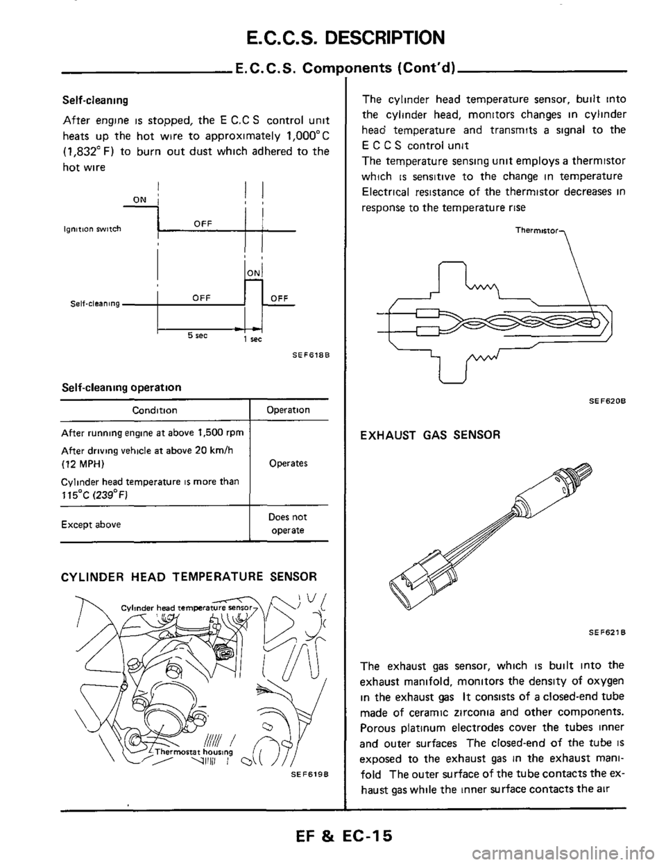
Self-cleaning
After engine is stopped, the E C.C S control unit
heats up the hot wire to approximately
1,OOO"C
(1,832"F) to burn out dust which adhered to the
hot wire
- - 1 rec 5 rec
SEF618B
Self-cleaning operation
Condition _____~ ~
After running engine at above 1,500 rpm
After driving vehicle at above
20 kmlh
(12 MPH)
Cylinder head temperature is more than
115OC
(239°F)
Except above
Operation
Operates
Does not
operate
CYLINDER HEAD TEMPERATURE SENSOR
SEF6198
nents (Cont'd)
The cylinder head temperature sensor, built into
the cylinder head, monitors changes in cylinder
head temperature and transmits
a signal to the
E C C S control unit
The temperature sensing unit employs
a thermistor
which
is sensitive to the change in temperature
Electrical resistance
of the thermistor decreases in
response to the temperature
rise
Thermmor
U
SEF6208
EXHAUST GAS SENSOR
SEF621
The exhaust gas sensor, which is built into the
exhaust manifold, monitors the density
of oxygen
in the exhaust gas It consists of a closed-end tube
made
of ceramic zirconia and other components.
Porous platinum electrodes cover the tubes inner
and outer surfaces The closed-end
of the tube IS
exposed to the exhaust gas in the exhaust mani-
fold The outer surface
of the tube contacts the ex-
haust
gas while the inner surface contacts the air
EF & EC-15
Page 20 of 79
E.C.C.S. DESCRIPTION
Fuel Injection Control
Temperature of engine Cylinder head temperature sensor
Density of oxygen in exhaust gas Exhaust gas sensor
Throttle valve idle position ' Throttle valve switch
Engine speed and piston position
Amount of intake air Air flow meter
ECCS
I I
I
control
Gear position unit NeutraVPark switch (VG30ET) I I
Vehicle speed
Start signal
Temperature of fuel
Battery voltage Battery
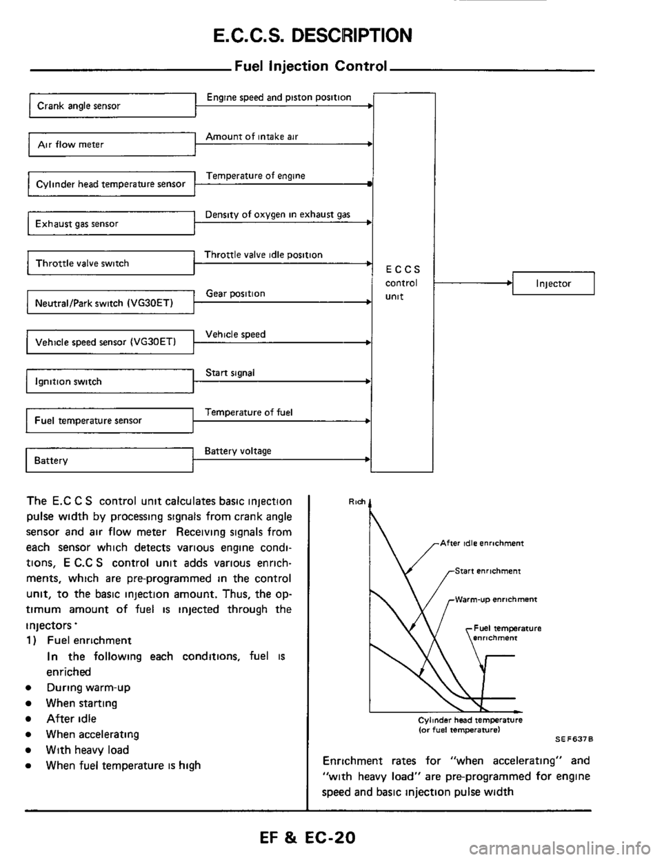
The E.C C S control unit calculates basic injection
pulse
width by processing signals from crank angle
sensor and air flow meter Receiving signals from
each sensor which detects various engine condi-
tions,
E C.C S control unit adds various enrich-
ments, which are pre-programmed
in the control
unit, to the basic injection amount. Thus, the op-
timum amount of fuel is injected through the
injectors.
1 ) Fuel enrichment
In the following each conditions, fuel is
enriched
e During warm-up
When starting
After idle
e When accelerating
e With heavy load
e When fuel temperature is high
.I Injector
Rlch
' \/ .-Warm-u~ enrichment
Cylmder head temperature (or fuel temperature1 SE F637 0
Enrichment rates for "when accelerating" and
"with heavy load" are pre-programmed for engine
speed and basic injection pulse
width
EF & EC-20
Page 21 of 79
E. C. C. S. DESCRIPTION
Deceleration from @
Deceleration from @
Deceleration from 0 or @
Fuel Injection
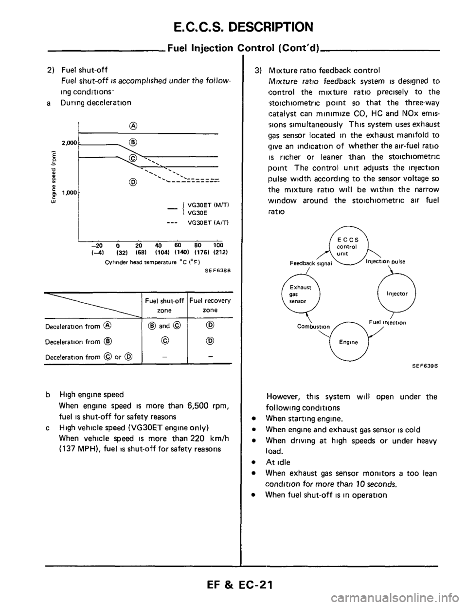
2) Fuel shut-off
Fuel shut-off is accomplished under the follow-
ing conditions.
a During deceleration
@ and @ 62
0 (E9
- -
- -.. . . . ._ '. .
VG30ET (MITI
VG30E
_-- VGXIET IA/Tl
-20 0 20 40 60 SO 100
(-41 1321 (681 11041 (1401 (1761 12121
Cvlinder head IemPerature "C 1°F)
SEF638B
b High engine speed
When engine speed is more than 6,500 rpm,
fuel
is shut-off for safety reasons
High vehicle speed
(VG30ET engine only)
When vehicle speed
is more than 220 km/h
(137 MPH), fuel is shut-off for safety reasons
c
mtrol (Cont'd)
3) Mixture ratio feedback control
Mixture ratio feedback system is designed to
control the mixture ratio precisely to the
*stoichiometric point
so that the three-way
!catalyst can minimize
CO, HC and NOx emis-
';ions simultaneously This system
uses exhaust
gas senwr located in the exhaust manifold to
give an indication of whether the air-fuel ratio
is richer or leaner than the stoichiometric
point The control unit adjusts the injection
pulse width according to the sensor voltage so
the mixture ratio will be within the narrow
window around the stoichiometric
air fuel
ratio
eontroi
Injector
0
Combustm
Engme
However, this system will open under the
following conditions
When starting engine.
When engine and exhaust
gas sensor is cold
When driving
at high speeds or under heavy
load.
At idle
When exhaust
gas sensor monitors a too lean
condition for more than
10 seconds.
When fuel shut-off
is in omration
EF & EC-21
Page 23 of 79
E. C. C. S. DESCRIPTION
Ignition Timing Control
Engine speed and piston position Crank angle sensor
Amount of intake air Air flow meter
Temperature of engine Cylinder head temperature sensor
Throttle valve idle position
Vehicle speed Vehicle speed sensor (VG30ETl 1 I I
Start signal Ignition switch
Engine knocking Detonation sensor
Battery voltage Battery ~
Ignition
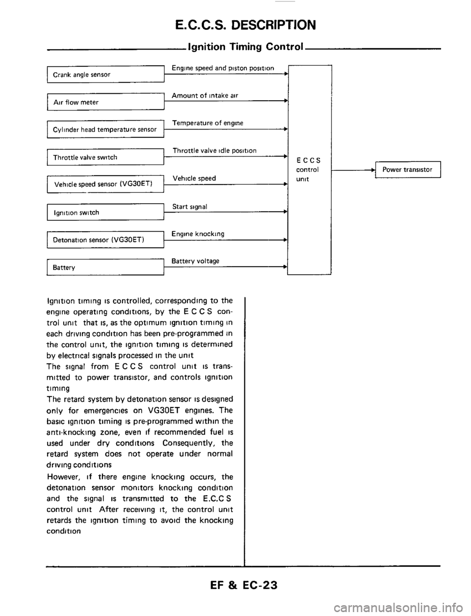
timing is controlled, corresponding to the
engine operating conditions, by the
E C C S con-
trol unit that
is, as the optimum ignition timing in
each driving condition has been pre-programmed in
the control unit, the ignition timing
IS determined
by electrical signals processed in the unit
The signal from
E C C S control unit is trans-
mitted to power transistor, and controls ignition
timing
The retard system by detonation sensor
is designed
only for emergencies on VG30ET engines. The
basic ignition timing
is pre-programmed within the
anti-knocking zone, even
if recommended fuel is
used under dry conditions Consequently, the
retard system does not operate under normal
driving conditions
However,
if there engine knocking occurs, the
detonation sensor monitors knocking condition
and the signal is transmitted to the E.C.C S
control unit After receiving it, the control unit
retards the ignition timing to avoid the knocking
condition
Power transistor
EF & EC-23
Page 25 of 79
E. C. C. S. DESCRIPTION
Start signal ’ Ignition switch
Throttle valve idle position
Neutral position t
Battery voltage Battery
Idle Speed Control (VG30ET engine)
Engine speed
Engine temperature
ECCS
control
Unlt
-
The idle speed is controlled by the E.C C S. control
unit, corresponding to the engine operating condi-
tions
The E C C S control unit senses the engine
condition and determines the best idle speed
at
each cylinder head temperature and gear position
The control unit then sends an electronic signal
corresponding
to the difference between the best
idle speed and the actual idle speed to the A A C.
valve.
I
,/ lAiC”ON”1 -‘I E .. -
P - 0 E 4 1 - - - -L- - - - - - lZN)
500 w
LAiT (”0”. A/C ”ON1
I -20 0 20 40 60 80 1M) 14) I321 168) 11041 1140) 1176) (212)
Cylinder head ternprature “C (OF1
SEF641B
Auxiliary air control valve
EF & EC-25
Page 30 of 79
DIAGNOSTIC PROCEDURE
Driveabil
1. Inspect engine and E C C.S. for air leaks,
proper electrical connections, etc
1) Check all hoses and ducts for air leaks
2) Check air cleaner for clogging
3) Check harness connectors for proper connec-
tions
4) Check ignition wiring
5) Check gaskets for leaks at all air intake com-
ponents
6) Check E G.R valve operation
7) Check air regulator operation
2 Perform E C C S self-diagnosis
Follow the procedure in E CCS SELF-
DIAGNOSIS (Page EF & EC-35)
3 Check idle speed and ignition timing
a. Prepare the following conditions:
Headlampswitch' OFF
Heater blower: OFF
Air conditioner switch: OFF
Front wheel (Power steering model):
KEEP STRAIGHT AHEAD
b. Warm engine to operating temperature.
Check
and adjust as follows
[VG30E engine (Without turbocharger)]
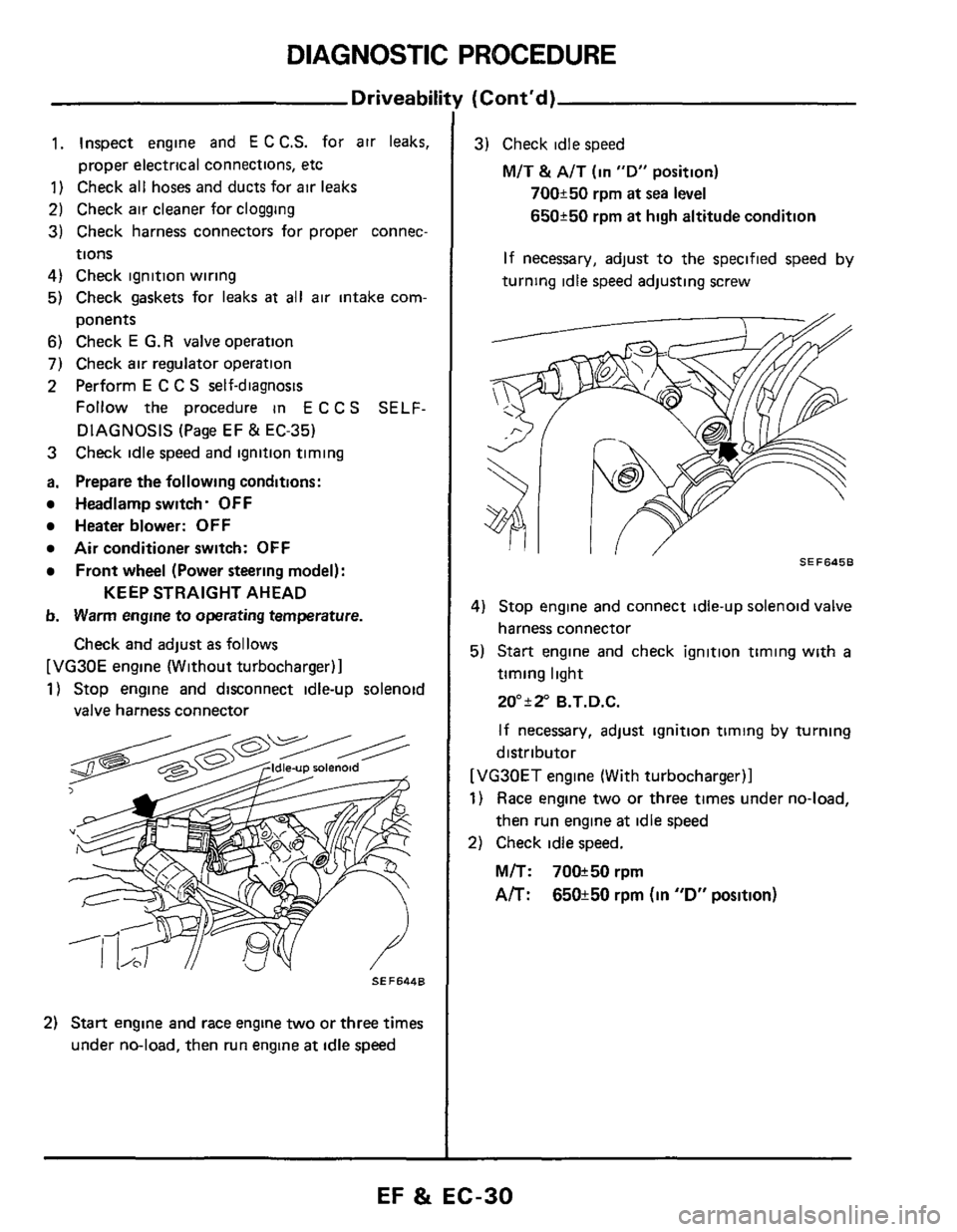
1) Stop engine and disconnect idle-up solenoid
valve harness connector
Idle-up solenoid
2) Start engine and race engine two or three times
under no-load, then run engine
at idle speed
(Cont'd)
3) Check idle speed
M/T & A/T (in "D" position)
700250 rpm at sea level
650250 rpm at high altitude condition
If necessary, adjust to the specified
speed by
turning idle speed adjusting screw
I, SEF6456
4) Stop engine and connect idle-up solenoid valve
harness connector
5) Start engine and check ignition timing with
a
timing light
20ai2" B.T.D.C.
If necessary, adjust ignition
timing by turning
distributor
[VG30ET engine (With turbocharger)]
1) Race engine two or three times under no-load,
then run engine at idle speed
2) Check idle speed.
M/T: 70W50rpm
A/T: 650k50 rpm (in "D" position)
EF & EC-30