Page 9 of 79
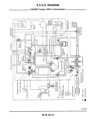
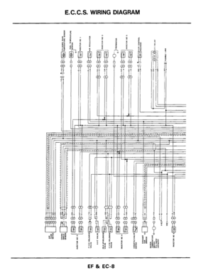
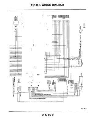
E.C.C.S. WIRING DIAGRAM
I'
.
...
.
SEF747B
EF & EC-9
Page 10 of 79
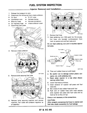
FUEL FLOW SYSTEM DESCRIPTION
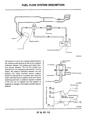
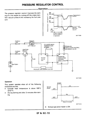
The amount of fuel to be injected is determined by
the injection pulse duration
as well as by a pressure
difference between fuel pressure and intake mani-
fold vacuum pressure. The
E.C C.S. control unit
controls only the injection pulse duration For this
reason,
the pressure difference between the fuel
pressure and intake manifold vacuum pressure
should be maintained
at a constant level Since the
intake manifold vacuum pressure varies with engine
operating conditions,
a pressure regulator IS placed
in the fuel line to regulate the fuel pressure in
response to changes
in the intake manifold vacuum
pressure
Fuel pump and damper
’ iFueirank
SEF604B
intake manifold 0 vacuum
a From fuel tank
Fuel chamber
SEF605B
Fuel presswe
EF & EC-10
Page 11 of 79
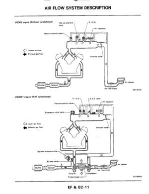
AIR FLOW SYSTEM DESCRIPTION
Air cleaner
VG30E engine (Without turbocharger) up roleno,,, FlCD
r
Valve
0 Intake air flow
C Exhaust gar flow
VGJOET engine (With turbocharger)
Vacuum control valve
Emergency relief valve
0 Intake air flow
Exhaust gar flow
cleaner
Turbbne
Turbocharger - unit- \Compresor SE F 608 B
EF & EC-11
Page 12 of 79

AIR FLOW SYSTEM DESCRIPTION
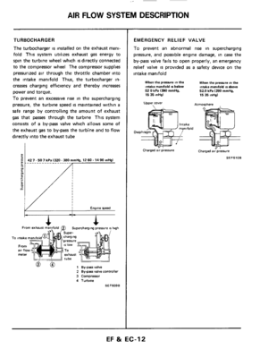
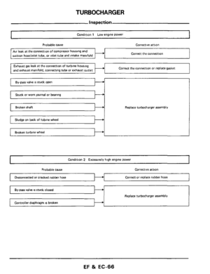
TURBOCHARGER
The turbocharger is installed on the exhaust mani-
fold This system utilizes exhaust gas energy to
spin the turbine wheel which
is directly connected
to the compressor wheel The compressor supplies
pressurized air through the throttle chamber into
the intake manifold Thus, the turbocharger in-
creases charging efficiency and thereby increases
power and torque.
To prevent an excessive rise in the supercharging
pressure, the turbine speed
is maintained within a
safe range by controlling the amount of exhaust
gas that passes through the turbine This system
consists of
a by-pass valve which allows some of
the exhaust gas to by-pass the turbine and to flow
directly into the exhaust tube
Engine speed
From b==iF exhausi man2fold 0 Superchargang pressure 41 hqh
To intake
From air flo meter
h
To intake
From air flo meter
2 Bygars valve controller
3 Compressor
4 Turbine
SEF609B
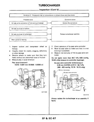
EMERGENCY RELIEF VALVE
To prevent an abnormal rise in supercharging
pressure, and possible engine damage, in case
the
by-pass valve fails to open properly, an emergency
relief valve
is provided as a safety device on the
intake manifold
When the prwre in the Intake mandold IS below 52 0 kPa 1390 mmHg. 15 35 inHgl
Upper cover
When the prerrura tn the intake mandold IS above 520 kPa 1390 mrnHg, 15 35 mHg)
Atmosphere
Charged air pressure Charged air pressure
SEF6lOB
EF & EC-12
Page 13 of 79

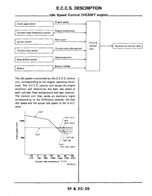
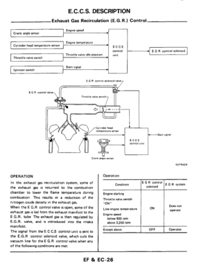
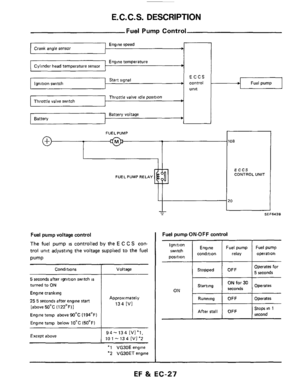
E.C.C.S. DESCRIPTION
E.C.C.S.
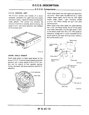
E C C.S. CONTROL UNIT
The E C C S control unit consists of a micro-
computer, connectors for signal input and output
and power supply, inspection lamps and diagnostic
mode selector The control unit controls the
amount
of fuel that is injected, ignition timing, idle
speed,
E G R , fuel pump operation, and feedback
of the mixture ratio
SEF611 B
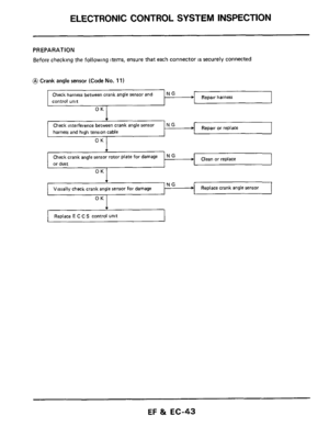
CRANK ANGLE SENSOR
Crank angle sensor is a basic signal sensor for the
entire
E C C S It monitors engine speed and piston
position, and
it sends signals to the E C C S con-
trol unit for control of
fuel injection, ignition
timing, idle speed, fuel pump operation and
E G R
operation.
rnponents
Crank angle sensor has rotor plate and wave form-
ing circuit Rotor plate has
360 slits for 1" signal
(engine speed signal) and
6 slits for 120" signal
(crank angle signal) Light Emitting Diodes
(L
E D ) and Photo Diodes are built into wave
forming circuit
When
signal rotor plate passes the space between
the
L E D and Photo Diode, the slit of the signal
rotor plate alternately cuts the light which
is sent
to
the photo diode from the L E D This causes an
alternative voltage and
it is then converted into an
on-otf pulse by the wave forming circuit, which IS
sent to the control unit
Sealed mwr
Rotor head
.-- ? Lighremitring -. - diode 'I- 1- . ;-- , -
. A. -7. l.lll- i:--, .J
- I -, _,- I- ..
. ir- .I
4,,
Phatodlodel fi-. h- 1 ,h
Wave forming-' circurt '-Rotor piate
SEFBlJB
Rotor plate
SEF614B
EF & EC-13
Page 14 of 79

A
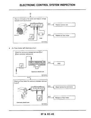
Air flow meter 0.
C
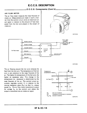
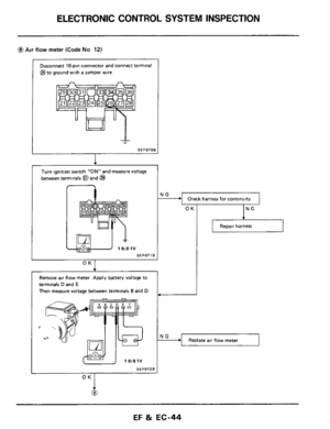
AIR FLOW METER
The air flow meter measures the mass flowrate of
intake air. Measurements are made in such
a man-")
E.C.C.S. DESCRIPTION
E.C.C.S. Components (Cont'd)
A
Air flow meter 0.
C
AIR FLOW METER
The air flow meter measures the mass flowrate of
intake air. Measurements are made in such
a man-
ner
that the control circuit emits an electrical out-
put signal
in relation to the amount of heat dissi-
pated from the hot wire placed
in the stream of
intake
air.
E F I relay
Battery source
Output voltage
Variable resistor
25 unit Ground
Self-cleaning ignition switch
Ground
El -
-
6- 31 27 35 1
w30 ECCS 6 comroi
F- 12 34 -
-
I SEF615B
SEFSlSB
The air flowing around the hot wire removes the
heat from
the hot wire The temperature of the hot
wire
is very sensitive to the mass flowrate of the
air.
The higher the temperature of the hot wire, the
higher
its resistance value This change in the
temperature (or. resistance)
IS determined by the
mass flowrate of the air. The control circuit
ac-
curately regulates current (I) in relation to the
varying resistance value
(RH) so that VA always
equals VB The air flow meter transmits an output
for voltage
VA to the control unit where the
output
is convened into an intake air signal.
I
Temperature compensation resistor
twire
Hot wore reststance
Temperature campenration resistance RA. RB Constant reSiiIanCe
RH RK
SEFS17B
I
EF & EC-14
Page 15 of 79
 to burn out dust which adh")
E. C. C. S. DESCRIPTION
E.C.C.S. Corn1
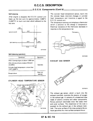
Self-cleaning
After engine is stopped, the E C.C S control unit
heats up the hot wire to approximately
1,OOO"C
(1,832"F) to burn out dust which adhered to the
hot wire
- - 1 rec 5 rec
SEF618B
Self-cleaning operation
Condition _____~ ~
After running engine at above 1,500 rpm
After driving vehicle at above
20 kmlh
(12 MPH)
Cylinder head temperature is more than
115OC
(239°F)
Except above
Operation
Operates
Does not
operate
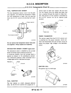
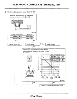
CYLINDER HEAD TEMPERATURE SENSOR
SEF6198
nents (Cont'd)
The cylinder head temperature sensor, built into
the cylinder head, monitors changes in cylinder
head temperature and transmits
a signal to the
E C C S control unit
The temperature sensing unit employs
a thermistor
which
is sensitive to the change in temperature
Electrical resistance
of the thermistor decreases in
response to the temperature
rise
Thermmor
U
SEF6208
EXHAUST GAS SENSOR
SEF621
The exhaust gas sensor, which is built into the
exhaust manifold, monitors the density
of oxygen
in the exhaust gas It consists of a closed-end tube
made
of ceramic zirconia and other components.
Porous platinum electrodes cover the tubes inner
and outer surfaces The closed-end
of the tube IS
exposed to the exhaust gas in the exhaust mani-
fold The outer surface
of the tube contacts the ex-
haust
gas while the inner surface contacts the air
EF & EC-15
Page 16 of 79

E.C.C.S. DESCRIPTION
E. C. C. S. Corn1
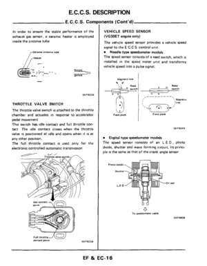
In order to ensure the stable performance of the
exhaust
gas sensor, a ceramic heater is employed
inside the zirconia tube
,-Ceramic zirmnia tube
.- . .. . ... .. . . . . . .. .. --_
SEF622B
THROTTLE VALVE SWlTCl
The throttle valve switch is attached to the throttle
chamber and actuates in response
to accelerator
pedal movement
This switch has idle contact and full throttle con-
tact The idle contact closes when the throttle
valve
is positioned at idle and opens when it is at
any other position.
The full throttle contact
is used only for the
electronic controlled automatic transmission
SEF623B
Full throttle contact p0,nt
nents (Cont'd)
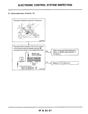
VEHICLE SPEED SENSOR
(VG30ET
engine only)
The vehicle speed sensor provides a vehicle speed
signal
to the E C.C S. control unit
Needle type speedometer models
The speed sensor consists of
a reed switch, which IS
installed in the speed meter unit and transforms
vehicle
speed into a pulse signal.
Magnetic line
\# Reed \I
i : !' sw17CI i N S"
Field 0 plate Field plate
SEF624B
Digital type speedometer models
The speed sensor consists of
an L E D , photo
diode, shutter and wave forming circuit.
Its princi-
ple
is the same as that of the crank angle sensor
011 seal
0 To speedometer cable
SEFS80B
EF & EC-16


 up roleno,,, FlCD
r
Valve
0 Intake air flow
C Exhaust gar flow
VGJOET engine (With turbocharger)
Vacuum control va")