Page 57 of 79
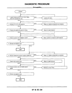
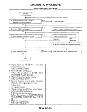
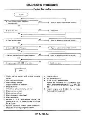
ELECTRONIC CONTROL SYSTEM INSPECTION
OK -
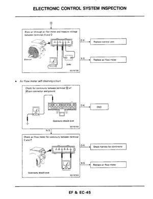
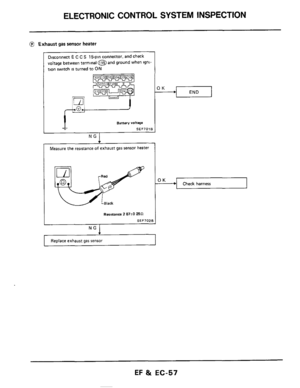
@ Exhaust gas sensor heater
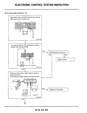
Disconnect E C C S 15-pm connector, and check
voltage between terminal@ and ground when igni
tion switch
IS turned to ON
Check harness
I J
Battery dtqe
SEF701
NG
+
Measure the resistance of exhaust gas sensor heater
Renslance 2 87kO Pa
SEF702E
NG I
Replace exhaust gas sensor
EF & EC-57
Page 58 of 79
ELECTRONIC CONTROL SYSTEM INSPECTION
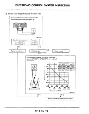
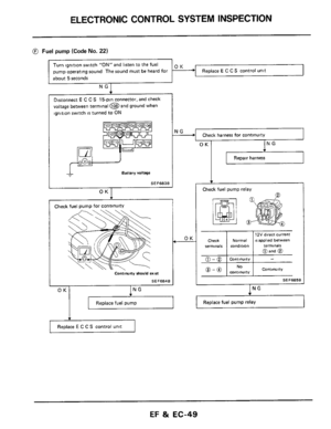
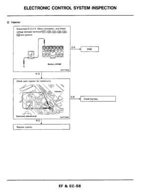
@ Injector
Disconnect E C C S 15pln connector, and check
voltage between terminal@,@,@,@,@,
@and ground
n
Battery voltage
SEF703B
NG I
Check each injector for continuity
SEF7MB COnttnuny should exin
4
Replace injector
END OK
Check harness
EF & EC-58
Page 59 of 79
ELECTRONIC CONTROL SYSTEM INSPECTION
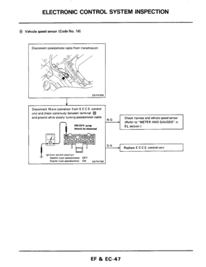
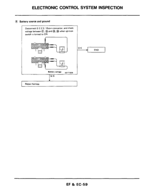
@ Battery source and ground
Dlsconnect E C C S 16-pin connector, and check
voltage between
a, @and @,@ when lgnltlon
switch
IS turned to ON
J .
J
Battery voltage SEF705B I
NG
Repair harness
EF & EC-59
Page 60 of 79
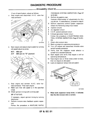
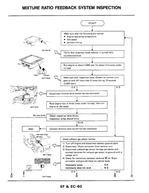
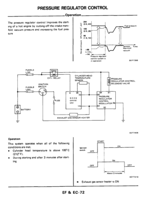
MIXTURE RATIO FEEDBACK SYSTEM INSPECTION
SEF707B
START
-
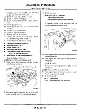
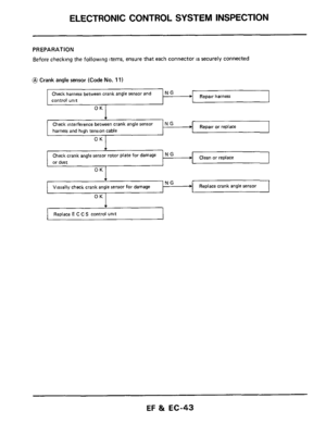
Make sure that the following are normal
engine at idle speed
SEF651B
SEF70BB
een
jumper wire.
connector and ground metal
on vehicle body
Continuity exists
. . .. .. . . 0 K.
Continuity does not exist . . .. N G
4) Check for continuity between terminal @ of 16-pin
SEF706B
t
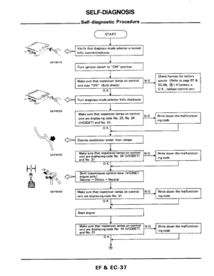
Verify that diagnosis mode selector is turned fully
cou nterclockwise
1
Run engine at about 2,000 rpm for about 2 minutes under
no-load
I
4
Make sure that inspection lamp (Green) on control unit
aoes
on and off more than 5 times durinq 10 seconds
I i2~000 rom) .. .~,. ~ ~
OK
Disconnect throttle valve switch harness connector
1
I Race engine two or three times under no-load, then run I
I JG
1
SEF709B
EF 81 EC-60
Page 61 of 79
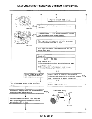
MIXTURE RATIO FEEDBACK SYSTEM INSPECTION
Repair or replace E C C S harness
SEF71OB
SEF7118
f
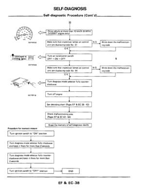
Connect a resistor (2.5 kS2) between terminals of cylinder
head temperature sensor harness connector
I
Start engine and warm up engine until water temperature
indicator points to the middle
of gauge
Race engine two or three times under no-load. then run
engine
at idle speed
After checking CO%,
1) Disconnect the resistor from terminals of cylinder head
temperature sensor
2) Connect cylinder head temperature sensor harness
connector to cylinder head temperature sensor
ness, and disconnect throttle inspection lamp on control unit goes on and off more
I
Turn off engine and remove air flow meter from
vehicle ~~
Drill a hole
in seal plug which seals variable resistor of
air flow meter and remove seal plug
warm up engine until water temperature indicator
Varrable resistor scmw
SEF7128
Page 62 of 79
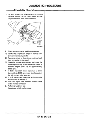
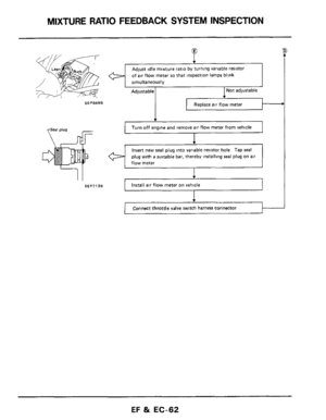
MIXTURE RATIO FEEDBACK SYSTEM INSPECTION
SEF7138
SEF649B
Install air flow meter on vehicle
P
of air flow meter so that inspection lamps blink
Not adjustable Adjustable
Replace air flow meter
Turn off engine and remove air flow meter from vehicle
1
Insert new seal plug into variable resistor hole Tap seal
plug with a suitable bar, thereby installing seal plug on air
flow meter
1 Connect throttle valve switch harness connector I---
EF & EC-62
Page 63 of 79

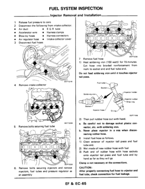
FUEL SYSTEM INSPECTION
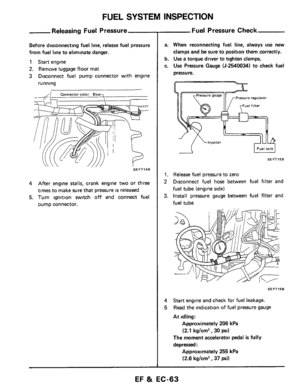
Releasing Fuel Pressure
Before disconnecting fuel line, release fuel pressure
from fuel line to eliminate danger.
1 Start engine
2. Remove luggage floor mat
3 Disconnect fuel pump connector with engine
running
SEF7148
4 After engine stalls, crank engine two or three
times to make sure that pressure
IS released
5. Turn ignition switch off and connect fuel
pump connector.
--Fuel Pressure Check
a. When reconnecting fuel line, always use new
clamps and be sure to position them correctly.
b. Use a torque driver to tighten clamps.
c.
Use Pressure Gauge (5-2540034) to check fuel
pressure.
I Fuel tank I -A
SEF7158
1. Release fuel pressure to zero
2 Disconnect fuel hose between fuel filter and
Fuel tube (engine side1
3. Install pressure gauge between fuel filter and
Fuel tube
SEF7168
4
5
Start engine and check for fuel leakage.
Read the indication of fuel pressure gauge
At idling:
Approximately 206 kPa
(2.1 kg/cm2, 30 psi)
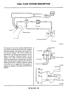
The moment accelerator pedal is fully
depressed
:
Approximately 255 kPa
(2.6 kg/cm2, 37 psi)
EF & EC-63
Page 64 of 79
FUEL SYSTEM INSPECTION
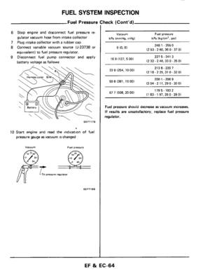
Fuel Pressure Check (Cont'd)
6 Stop engine and disconnect fuel pressure re-
gulator vacuum hose from intake collector
7
Plug intake collector with a rubber cap
8 Connect variable vacuum source (J-23738 or
equivalent) to fuel pressure regulator.
9 Disconnect fuel pump connector and apply
battery voltage
as follows
SEF717B
10 Start engine and read the indication of fuel
pressure gauge as vacuum is changed
Vacuum Fuel prerrure
SEF718B
Vacuum Fuel pressure
kPa (mmHg, inHg) kPa (kg/cm2, psi1
0 (0.01 248 1 .255 0
(2 53
- 2 60.36 0.37 01
227 5.241 3
(2 32.2 46,330.35
01 16 9 (127, 5 00)
213 8.220 7
(2 18.2 25,31 0 - 32 01 33 9 (254. 10 001
200 1 - 206 9
(2 04
- 2 11.29 0- 30 01 50 8 (381,15 00)
179 5. 193 2
(1 83-197.260-280) 67 7 (508.20 00)
Fuel pressure should decrease as vacuum increases.
If results are unsatisfactory, replace fuel pressure
regulator.
EF 8t EC-64


 between terminals of cylinder
head temperature sensor harness conne")


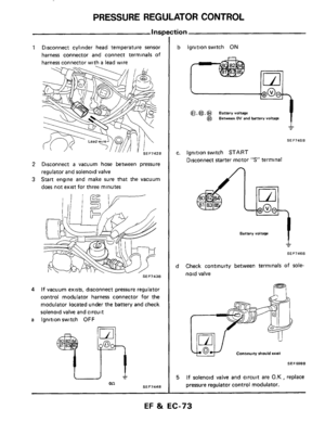
6 Stop engine and disconnect fuel pressure re-
gulator vacuum hose from intake collector
7
Plug intake collector with a rubber cap
8")