Page 65 of 79

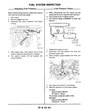
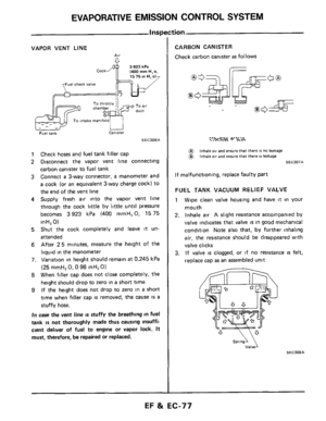
FUEL SYSTEM INSPECTION
Injector Removi
1
2
Air duct E G R tube
Accelerator wire Harness clamps
Blow-by hoses Harness connectors
Air regulator hose Intakecollector cover
3 Disconnect fuel hoses
Release fuel pressure to zero
Disconnect the following from intake collector.
4 Remove intake collector
5 Remove bolts securing fuel tube
6. Remove bolts securing injectors and remove
injecton, fuel tubes and pressure regulator
as
an assembly
and installation
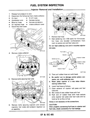
7 Remove fuel hose
1) Heat soldering iron (150 watt) for 15minutes
Cut hose into braided reinforcement from
mark to socket end and
fuel tube end.
Do not feed soldermg iron until it touches injector
tail piece.
Socket
Fuel tube
Injector holder Soldering iron
InjeCtor rubber
Snap rtng
injector hosef O-ring
SEF719B
2) Then pull rubber hose out with hand.
a.
Be careful not to damage socket plastic con-
nector, etc. with soldering
iron.
b. Never place injector in a VIS when dixon-
necting rubber hose.
8
Install fuel hose as follows.
1) Clean exterior of injector
tail piece and fuel
tube end.
2) Wet inside of new rubber hose with fuel
3) Push end of rubber hose with hose sockets
onto injector tail piece and fuel tube end by
hand
as far as they will go
Clamp is not necessary at the connections.
CAUTION:
After properly connecting fuel hose
to injector and
fuel tube, check connection
for fuel leakage.
EF & EC-65
Page 66 of 79
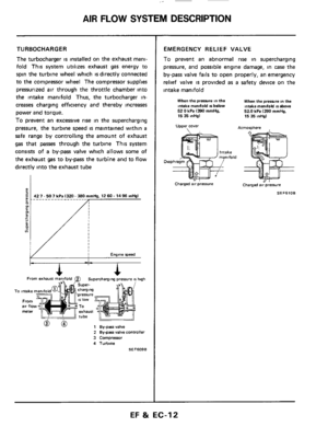
TURBOCHARGER
Disconnected or cracked rubber hose
I ~~ ~
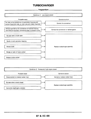
~ Condition 1 Low engine power
Probable cause Corrective action I
Correct or replace rubber hose
Air leak at the connection of compressor housing and
suction hoselinlet tube, or inlet tube and intake manifold Correct the connection
Correct the connection or replace gasket Exhaust gas leak at the connection of turbine housing
and exhaust manifold. connectina tube or exhaust outlet
I - I I I
Stuck or worn journal or bearing
Replace turbocharger assembly
Broken turbine wheel I--+
I Condition 2 Excessively high engine power 1
EF & EC-66
Page 67 of 79

Replace turbocharger assembly
I Condition 3 Excessively high oil consumption or exhaust shows pale blue smoke I
Probable cause C")
TURBOCHARGER
Worn journal or bearing
Inspection (Cont’d)
Replace turbocharger assembly
I Condition 3 Excessively high oil consumption or exhaust shows pale blue smoke I
Probable cause Corrective action
Oil leak at the connection of lubricating oil passage Correct the connection
1. Inspect turbine and compressor wheel as
follows
Visually check for cracks, clogging, deformity
or other damage
Revolve wheels to make sure that they turn
freely without any abnormal noise or friction
Measure play in axial direction
Play (axial direction):
0.013.0.091 mm (0.0005 - 0.0036 in)
SEF726B
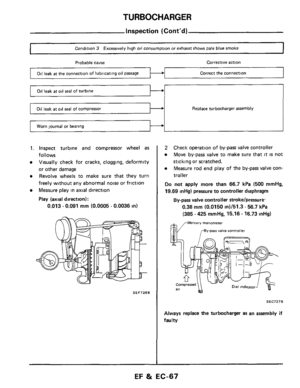
2 Check operation of by-pass valve controller
Move by-pass valve to make sure that
it is not
sticking or scratched.
Measure rod end play of the bypass valve con-
troller
Do not apply more than 66.7 kPa (500 mmHg,
19.69 mHg) pressure to controller diaphragm
0.38 mm (0.0150 in)/51.3 - 56.7 kPa
(385 - 425 mmHg, 15.16 - 16.73 inHg)
By-pass valve controller strokelpressure.
,vMercury manometer
,-By-parr valve controller
SEC7278
Always replace the turbocharger as an assembly if
faultv
EF & EC-67
Page 68 of 79
TURBOCHARGER
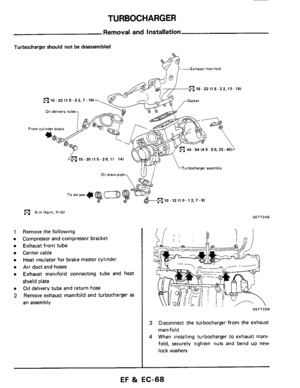
Removal and Installation
Turbocharger should not be disassembled
&- Exhaw manifold
(c1 18 -22 (1 8-22.13-161
10 -22 I1 0 -22.7.161
011 delivery tube
From cylinder block
*@
15-2OI15-20.11 14)
Turbocharger assembly
p? N m lkg-m. ft-lbl SEF724B
Remove the following
Compressor and compressor bracket
Exhaust front tube
Center cable
Heat insulator for brake master cylini
Air duct and hoses
Exhaust manifold connecting tube and heat
shield plate
Oil delivery tube and return hose
Remove exhaust manlfold and turbocharger
as
an assembly
SEF725B
3
4
Disconnect the turbocharger from the exhaust
manifold
When installing turbocharger
to exhaust mani-
fold, securely tighten nuts and bend
up new
lock washers
EF 8i EC-68
Page 69 of 79
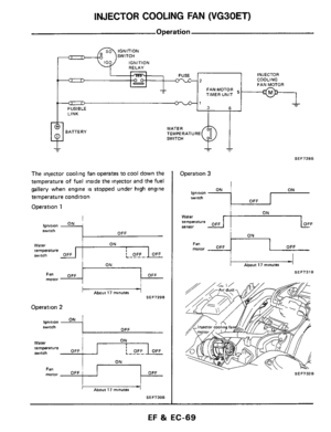
INJECTOR COOLING FAN (VG30ET)
-2
INJECTOR
COOLING
FAN MOTOR
The injector cooling fan operates to cool down the
temperature of fuel inside the injector and the fuel
gallery when engine is stopped under high engine
temperature condition
Operation 1
I
-1
lgnltl.3" ON
OFF switch
FANMOTOR TIMER UNIT
- - 3 6
Water I ON temperature witch
motor Fa" OFF 'PI OFF
Fa" motor OFF I
I About 17 monutes
SEF7296
OFF
Operation 2
ON Ignition switch OFF
ON
I iI
Water temperature witch OFF ~
Abut 17 minuter
SEF730B
Operation 3
ON I ON , Ignition twitch OFF
SEF7326
EF & EC-69
Page 70 of 79
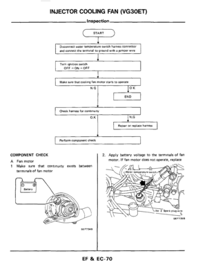
INJECTOR COOLING FAN (VG30ET)
Inspection
START
T
Disconnect water temperature switch harness connector
and connect the terminal to ground with
a jumper wire
I
Turn ignition switch
I OFF+ON+OFF L
1
I
Make sure that cooling fan motor starts to operate 1 NG I IOK I
1
Check harness for continuity ~~
[ Perform
component check
COMPONENT CHECK
A Fan motor
1 Make sure that continuity exists between
terminals of fan motor
SEF734B
2. Apply battery voltage to the terminals of fan
motor. If fan motor
does not operate, replace
SEF7358
EF & EC-70
Page 71 of 79

lnspectio
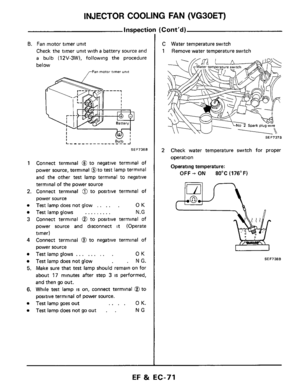
B. Fan motor timer unit
Check the timer unit with a battery source and
a bulb (12V-3W). following the procedure
below
,,-Fan motor timer unit
1 Con")
INJECTOR COOLING FAN (VG30ET)
lnspectio
B. Fan motor timer unit
Check the timer unit with a battery source and
a bulb (12V-3W). following the procedure
below
,,-Fan motor timer unit
1 Connect terminal @ to negative terminal of
power source, terminal @to
test lamp terminal
and the other
test lamp terminal to negative
terminal of the power source
2. Connect terminal @ to positive terminal of
power source
Test lamp does not glow ..... OK
Test lamp glows ......... N.G
3 Connect terminal @ to positive terminal of
power source and disconnect it (Operate
timer)
4 Connect terminal @ to negative terminal of
power source
Test lamp glows ......... OK
Test lamp does not glow . N G.
5. Make sure that test lamp should remain on for
about 17 minutes after step 3 is performed,
and then go out.
6. While test lamp is on, connect terminal @to
positive terminal of power source.
Test lamp goes out .... OK.
Test lampdoesnotgoout . . NG
(Corrt'd)
C \Mater temperature switch
1 IRemove water temperature switch
SEF737B
2 Check water temperature switch for proper
operation
Operating temperature:
OFF + ON 80°C (176°F)
SEF738B
EF & EC-71
Page 72 of 79
ZL-33 % A3
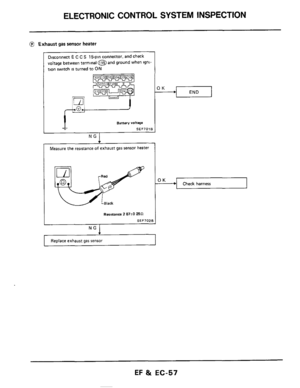
NO SI iaieaq iosuas se6 isneqx3
10tl
I
i
3snj
BSELJ3S
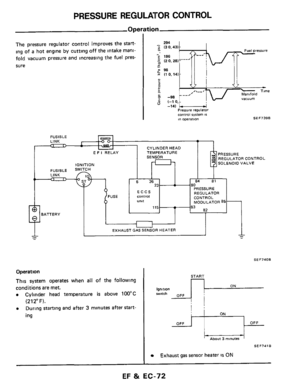


-2
INJECTOR
COOLING
FAN MOTOR
The injector cooling fan operates to cool down the
temperature of fuel inside the injector and the fuel
gallery when engine is stop")

Inspection
START
T
Disconnect water temperature switch harness connector
and connect the terminal to ground with
a jumper wire
I
Turn ignition switch
I O")
