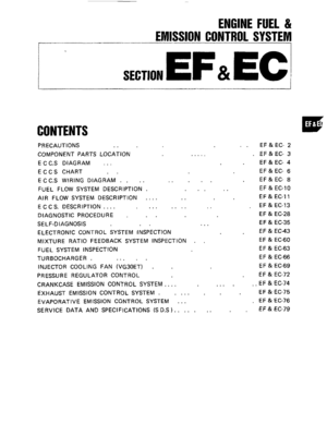
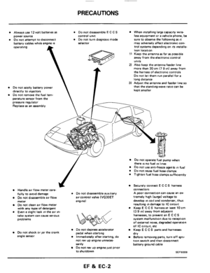
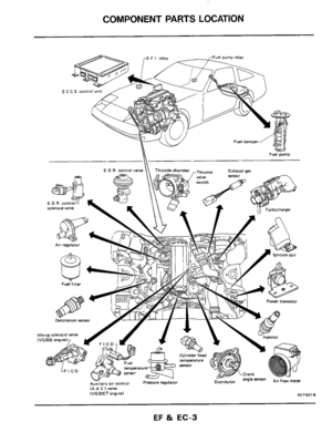
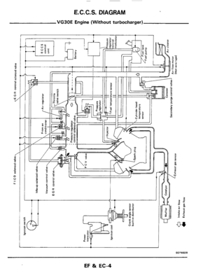
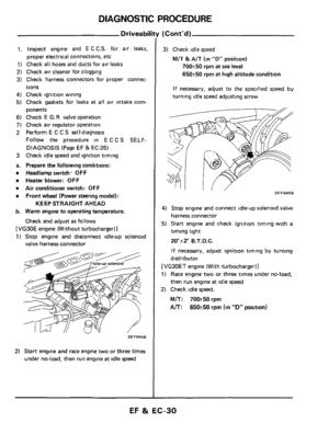
Page 41 of 79
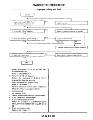
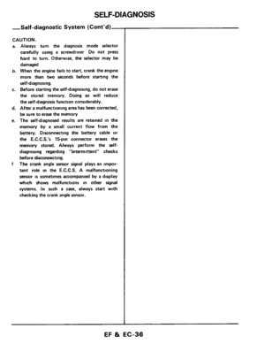
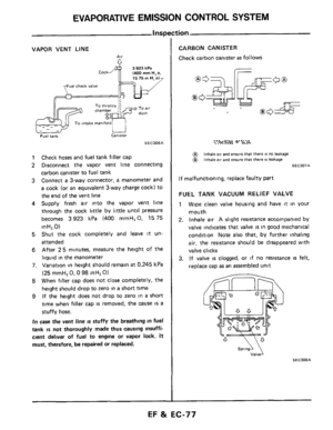
SELF-DIAGNOSIS
Decoding Chart (Cont'd)
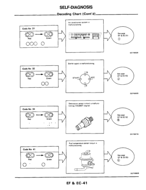
AK condnioner svstem I 16 malfunctioning
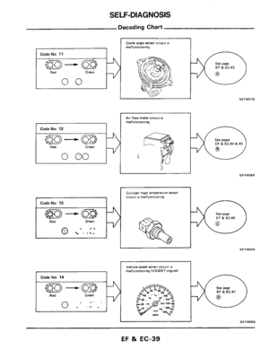
Code No 31 ~~
A ~ Green , ?/=%$== =- ~~ 0 Red
000 0
SEF665B
Starter rlgnal IS malfunctioning
Code
No 32
I2 SEF666B
CodeNo 34
Detonation sensor Circuit IS malfunc
tiontng IVG30ET enginel
See page
EF&EC52
SEF667B I ~
See
page EF & EC-53
I
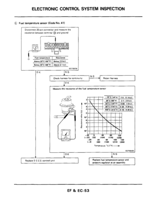
Fuel temperature sensor circuit IS malfunnmnlng
Code No 41
=-a
Red Green
0
II SEF668B
EF & EC-41
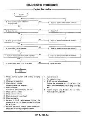
Page 42 of 79
SELF-DIAGNOSIS
Decoding Chart (Cont'd)
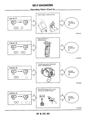
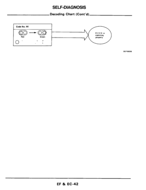
Code No. 44 ~
m-w -
Red Green
.,
0'
SEF669B
EF 81 EC-42
Page 43 of 79
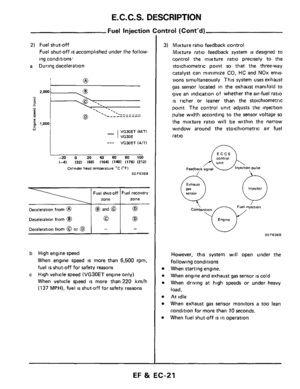
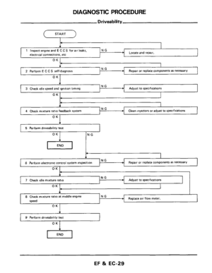
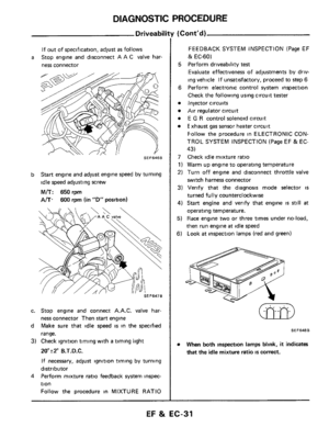
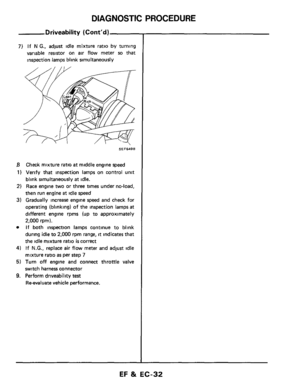
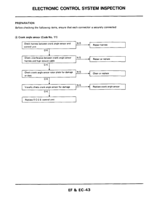
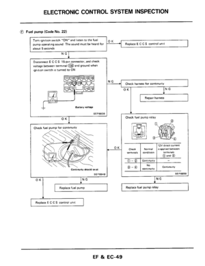
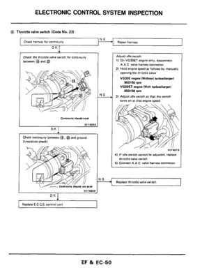
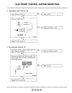
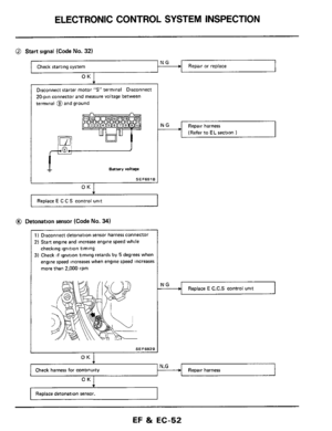
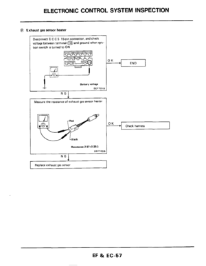
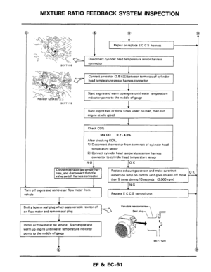
ELECTRONIC CONTROL SYSTEM INSPECTION
Check harness between crank angle sensor and
control unit
PREPARATION
Before checking the following items, ensure that each connector IS securely connected
N G ~ harness
Repair or replace harness and high tension cable
or dust
Visually check crank angle sensor for damage 1 “--+I Replace crank angle sensor
OK
Replace E C C S control unit 1
EF & EC-43
Page 44 of 79
ELECTRONIC CONTROL SYSTEM INSPECTION
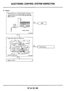
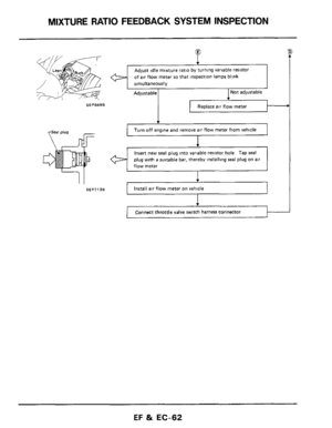
VG -
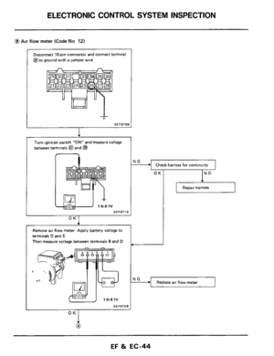
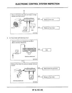
@Air flow meter (Code No 12)
Check harness for continuity
Disconnect 16pin connector and connect terminal
@to ground with
a jumper wire
NG -
Turn ignition switch ”ON” and measure voltage
between terminals @and
@I
Replace air flow meter
1 6tO 1V
SEF671B
O “I
Remove air flow meter Apply battery voltage to
terminals
D and E
Then measure voltage between terminals Band D
SEF672B
I
OK
7
IN
Repair harness
OK
@
EF 81 EC-44
Page 45 of 79
ELECTRONIC CONTROL SYSTEM INSPECTION
+I Replace control unit
t +I Replace air flow meter
Blow air through air flor meter and measure voltage
between terminals
B and D
Blo
I
I SEF6730
Air flow meter self cleaning circuit
Check for continuity between terminal @of
20-pin connector and ground
I
n
Contwny should extR
SEF6748
___~
Check air flow meter for continuity between terminal
C and F
Check harness for continuitv
Replace air flow meter
I Continuity should exis
SEF6750
EF & EC-45
Page 46 of 79
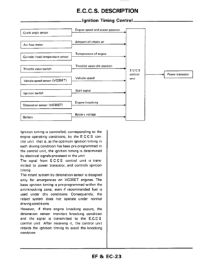
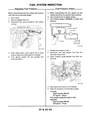
ELECTRONIC CONTROL SYSTEM INSPECTION
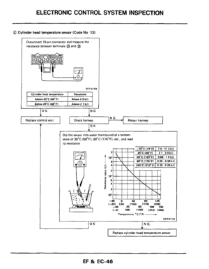
@ Cylinder head temperature sensor (Code No 13)
Disconnect 16-pin connector and measure the
resistance between terminals @and
@$
Dip the sensor into water maintained at a temper-
ature
of 20°C (68°F). 80°C (176°F). etc, and read
its resistance
2
I lo; - - c4
- ;2
c 66
g2
m : io3 u
z4 *
102
-30 0 40 80 120 (-221 I321 (1041 11781 (2481 -20 20 60 100 130 (-41 (681 (1401 (2121 (2661
Temperature "C (OF) -
SEF677B
(OK I N G.
Replace cylinder head temperature sensor
EF & EC-46
Page 47 of 79
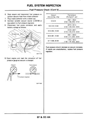
ELECTRONIC CONTROL SYSTEM INSPECTION
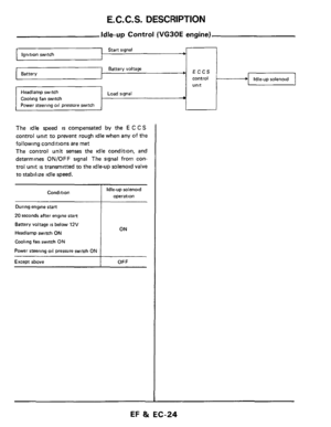
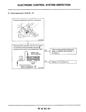
:@ Vehicle speed sensor (Code No. 14)
Disconnect speedometer cable from transmission
I
SEF678B
I
Disconnect 16-pin connector from E C C S control
unit and check continuity between terminal
@
and ground while slowly turning speedometer cable
ONIOFF puk should be detected n
(Refer to “METER AND GAUGES in
Replace E C C S control unit
EF & EC-4‘7
Page 48 of 79
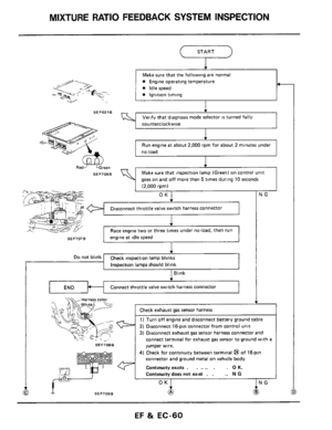
ELECTRONIC CONTROL SYSTEM INSPECTION
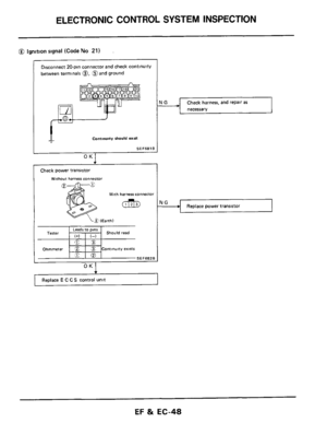
Tester
Ohmmeter
@ ignition signal (Code No 21)
Leads 'Ins ~ Should read I+) I-)
E&
CZ 3 Continuity exists
e@
A
SEF682E
Disconnect 20-pin connector and check continuity
between terminals 0. @and ground
Continuity should exst
SEF681B
OK1 ~~
Check
power transistor
Without harness Connector l
Wlth harness connector
Check harness, and repair as
necessarv
I
Replace E C C S control unit I
9 Replace power transistor I I I
EF & EC-48

AK condnioner svstem I 16 malfunctioning
Code No 31 ~~
A ~ Green , ?/=%$== =- ~~ 0 Red
000 0
SEF665B
Starter rlgnal IS malfunctioning
Code
No 32
I2 S")

Code No. 44 ~
m-w -
Red Green
.,
0
SEF669B
EF 81 EC-42")


Check harness for continuity
Disconnect 16pin connector and connect terminal
@to ground with
a jumper wire
NG -
Tu")


Disconnect 16-pin connector and measure the
resistance between terminals @and
@$
Dip the sensor into")

Disconnect speedometer cable from transmission
I
SEF678B
I
Disconnect 16-pin connector from E C C S control
unit a")

Leads Ins ~ Should read I+) I-)
E&
CZ 3 Continuity exists
e@
A
SEF682E
Disconnect 20-pin connector and")