Page 17 of 79
E. C. C. S. DESCRIPTION
E.C.C.S. Corn
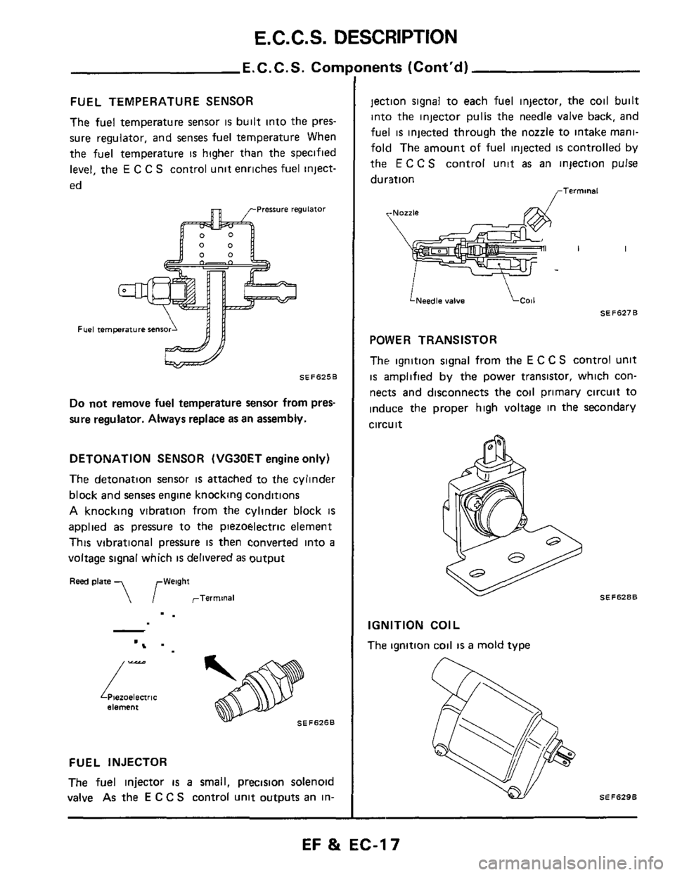
FUEL TEMPERATURE SENSOR
The fuel temperature sensor is built into the pres-
sure regulator, and senses fuel temperature When
the fuel temperature
IS higher than the specified
level, the
E C C S control unit enriches fuel inject-
ed
Pressure regulator
Fuel temprature $ens
SEF625B
Do not remove fuel temperature sensor from pres-
sure regulator. Always replace as
an assembly.
DETONATION SENSOR (VG30ET engine only)
The detonation sensor
is attached to the cylinder
block and senses engine knocking conditions
A knocking vibration from the cylinder block is
applied as pressure to the piezoelectric element
This vibrational pressure
IS then converted into a
voltage signal which is delivered as output
Reed plate ,, ,-Weight
rTerminal
-.
Piezoelectric element
SEFSZSB
/-
FUEL INJECTOR
The
fuel injector is a small, precision solenoid
valve As the
E C C S control unit outputs an in-
lnents (Cont’d)
jection signal to each fuel injector, the coil built
into the injector pulls the needle valve back, and
fuel
is injected through the nozzle to intake mani-
fold The amount of fuel injected
is controlled by
the
E C C S control unit as an injection pulse
duration
<-Nozzle
LNeedle valve
SEF627B
POWER TRANSISTOR
The ignition signal from the
E C C S control unit
is amplified by the power transistor, which con-
nects and disconnects the coil primary circuit to
induce the proper high voltage in the secondary
circuit
SEFSZBB
IGNITION COIL
The ignition coil
IS a mold type
EF & EC-17
Page 73 of 79
PRESSURE REGULATOR CONTROL
I nspi
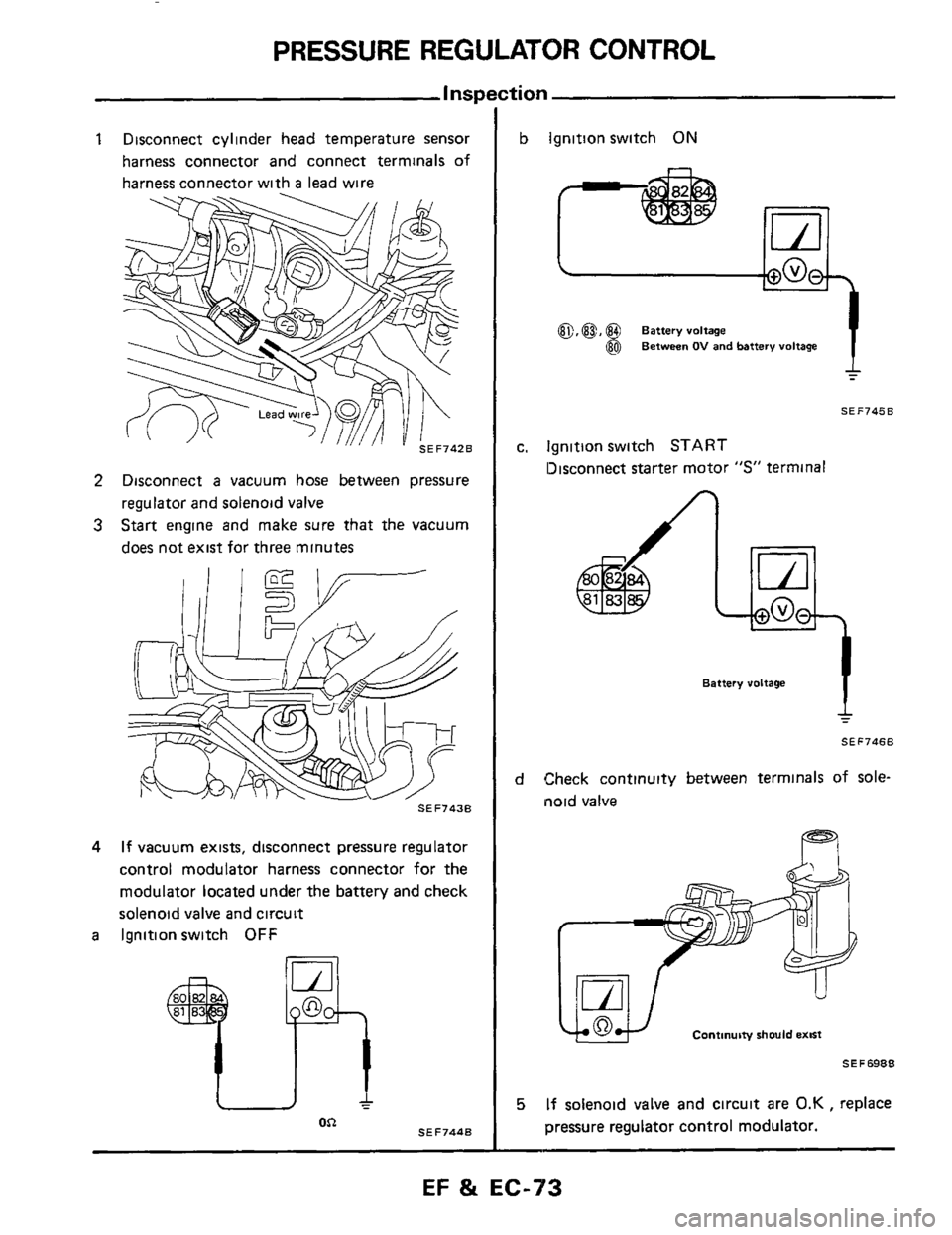
1 Disconnect cylinder head temperature sensor
harness connector and connect terminals of
harness connector with
a lead wire
2 Disconnect a vacuum hose between pressure
regulator and solenoid valve
3 Start engine and make sure that the vacuum
does not exist for three minutes
SEF743B
4 If vacuum exists, disconnect pressure regulator
control modulator harness connector for the
modulator located under the battery and check
solenoid valve and circuit
a Ignition switch OFF
SEF744B OR
b Ignition switch ON
a,@, @ Battery voltage
@ Between OV and battery voltage
SEF745B
c. lgnitlon switch START
13isconnect starter motor "S" terminal
I
Battery voltage
4
SEF7468
d Check continuity between terminals of sole-
noid valve
Continuity should emst
SE F 6988
5 If solenoid valve and circuit are 0.K , replace
pressure regulator control modulator.
-
EF & EC-73
Page 79 of 79
SERVICE DATA AND SPECIFICATIONS (S.D.S.)
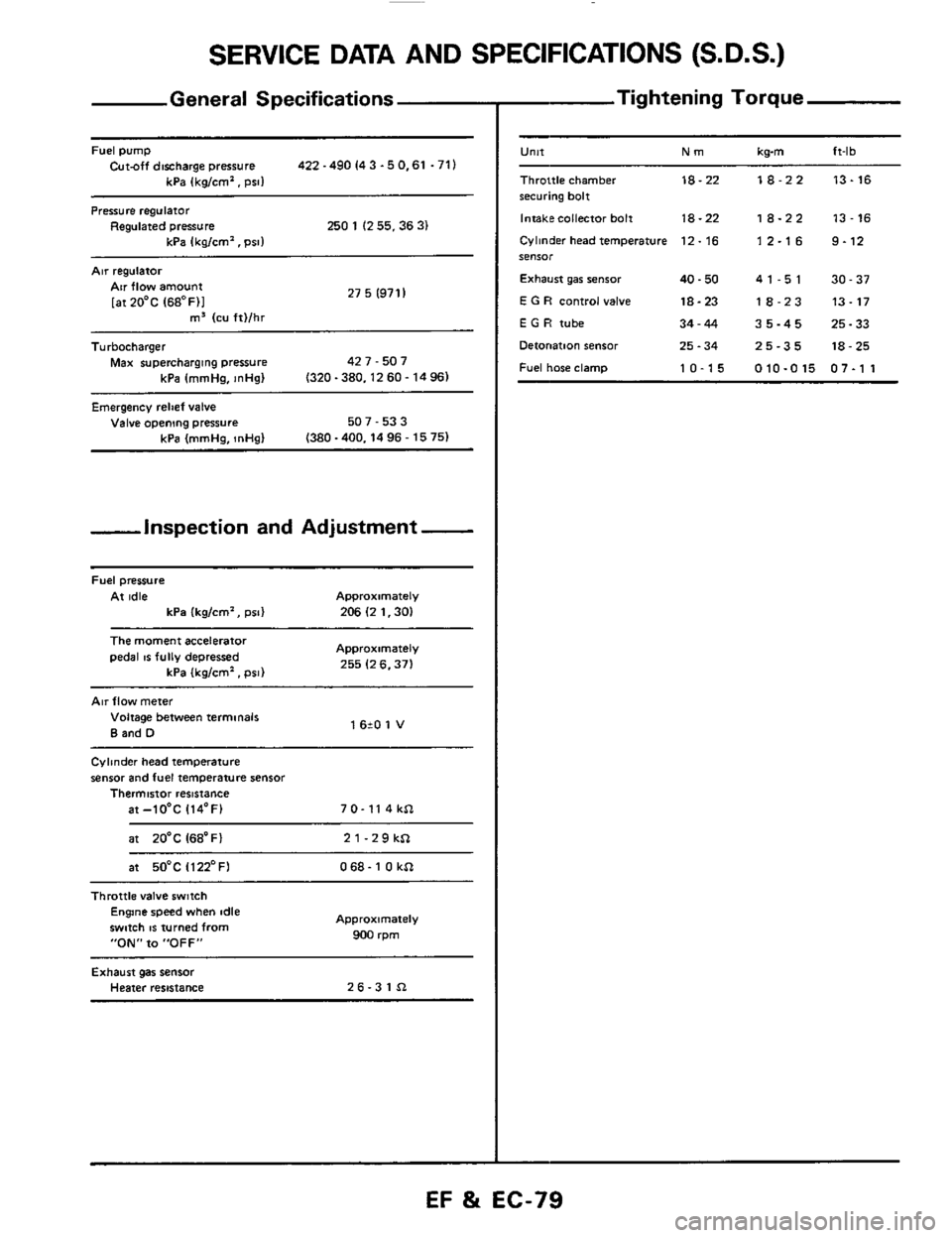
General Specifications
Fuel pump Cut-off discharge pressure 422 -490 I4 3 -5 0.61 .71)
kPa (kg/cm'. psi1
Pressure regulator Regulated pressure 250 1 (2 55.36 3) kPa Ikalcm'. Dsll
Air regulatoi
27 5 (971 I Air flow amount
[atZO'C (68OF)I m3 (cu ft)/hr ~~
Turbocharger
Max supercharging pressure 42 7 - 507
kPa (mmHa.
InHal (320-380.1260-1496)
Emergency relief valve Valve opening pressure 507 - 53 3
(380 -400.14 96 - 15 75) kPa (mmHg, InHg)
-inspection and Adjustment -
Fuel pressure
At idle Approximately
kPa (kg/cm', psi) 206 (2 1.30)
The moment accelerator
pedal IS fully depressed Approximately
255 (2 6.371 kPa (kglcm'. psi)
Air flow meter
Voltage between terminals
B and D 1 620 1 V
Cylinder head temperature
sensor and fuel temperature sensor Thermistor resistance
at-lO'C 114'F) 7 0- 11 4 kSl
at 20'C I68'Fl 21-29kSl
at 50°C Il22'FI 068- 1 0 kSl ~~~~
Throttle
valve switch Engine speed when idle
swmh
IS turned from
"ON" to "OFF"
Approximately
900 rpm
Exhaust gas sensor Heater resistance 26-31Sl
- Tightening Torque
-
U"lt Nm kwn ft-lb
Throttle chamber 18-22 18-22 13-16 securing bolt
Intakecollector bolt
18-22 18-22 13-16
Cylinder head temperature 12. 16 1 2.1 6 9.12 SeIlSOr
Exhaust gar senior 40.50 41-51 30-37
E G R control valve 18-23 18-23 13-17
E G H tube 34-44 35-45 25-33
Detonation sensor 25.34 25-35 18-25
Fuel hose clamp 10-15 010-015 07-1 1
EF %i EC-79