Page 25 of 79
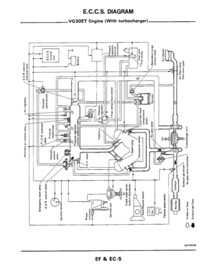
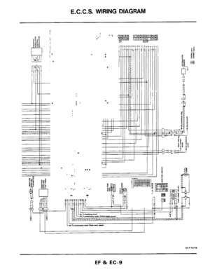
E. C. C. S. DESCRIPTION
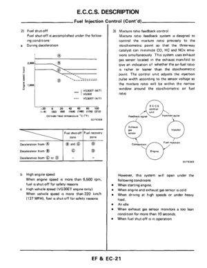
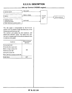
Start signal ’ Ignition switch
Throttle valve idle position
Neutral position t
Battery voltage Battery
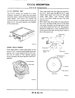
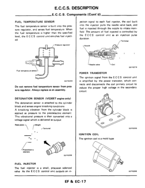
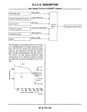
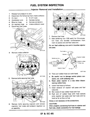
Idle Speed Control (VG30ET engine)
Engine speed
Engine temperature
ECCS
control
Unlt
-
The idle speed is controlled by the E.C C S. control
unit, corresponding to the engine operating condi-
tions
The E C C S control unit senses the engine
condition and determines the best idle speed
at
each cylinder head temperature and gear position
The control unit then sends an electronic signal
corresponding
to the difference between the best
idle speed and the actual idle speed to the A A C.
valve.
I
,/ lAiC”ON”1 -‘I E .. -
P - 0 E 4 1 - - - -L- - - - - - lZN)
500 w
LAiT (”0”. A/C ”ON1
I -20 0 20 40 60 80 1M) 14) I321 168) 11041 1140) 1176) (212)
Cylinder head ternprature “C (OF1
SEF641B
Auxiliary air control valve
EF & EC-25
Page 26 of 79
 Control
ECCS
c")
E.C.C.S. DESCRIPTION
Engine speed Crank angle sensor c
Engine temperature ’
Throttle valve idle position Throttle valve switch
Start signal
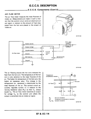
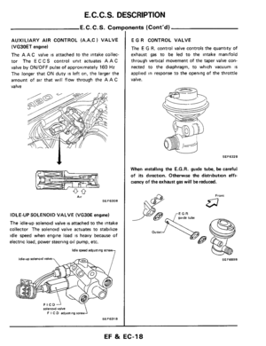
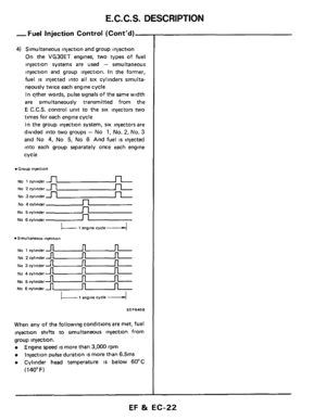
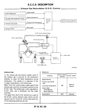
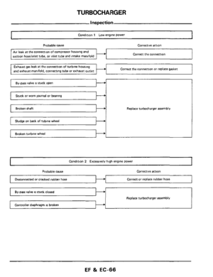
Exhaust Gas Recirculation (E.G. R.) Control
ECCS
control
unit
EGR
E G R control sclenoid valv
Throttle valve witch
C lhnder head era1“re semor
Crank angle sensor
OPERATION
In the exhaust gas recirculation system, some of
the exhaust
gas is returned to the combustion
chamber to lower
the flame temperature during
combustion This results
in a reduction of the
nitrogen oxide density in the exhaust
gas.
When the E G.R control valve is open, some of the
exhaust
gas is led from the exhaust manifold to the
E G.R. tube The exhaust gas is then regulated by
E.G.R. valve, and
is introduced into the intake
manifold.
The signal from the E C C.S control unit is sent to
the
E.G.R control solenoid valve, which cuts the
vacuum line for the E G.R control valve when any
of the following conditions are met
-Start signal
SE F642 B
I Operation
E G R system I
Condition E G R control
solenoid
Engine starting
Throttle valve switch
“ON”
Low engine temperature Does not
Engine speed
below 900 rpm
above 3,200 rpm
Operates Except above
EF & EC-26
Page 27 of 79
E.C.C.S. DESCRIPTION
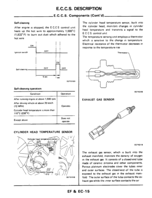
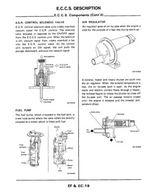
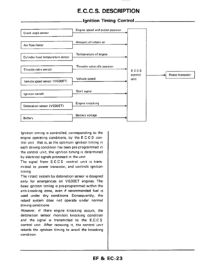
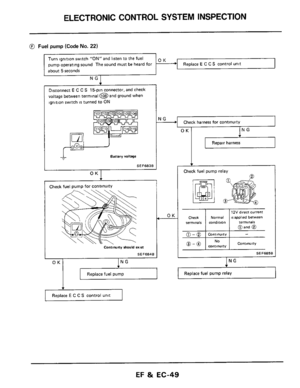
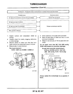
FUELPUMP ~
FUEL PUMP RELAY
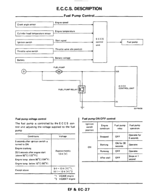
Fuel Pump Control
108
ECCS
CONTROL UNIT
Engine speed --r
Engine temperature
control Fuel pump Start signal
Ignition
switch
position Engine
condition
Throttle valve idle position
Fuel pump Fuel pump
relay operation
Battery voltage Battery
Starting ON
ON for 30 Operates
seconds
Fuel pump voltage control
The fuel pump is controlled by the E C C S con-
trol unit adjusting the voltage supplied to the fuel
pump
Conditions
5 seconds after ignition switch is
turned to ON
Engine cranking
25 5 seconds after engine stan
[above 50°C (122°F)1
Engine temp above 90°C (194OF)
Engine temp below 10°C (50°F)
Except above
Voltage
Approximately
134 [VI
94-134 [Vl'l,
10 1 - 13 4 [VI '2
'1 VG30E engine
"2 VG30ET engine
I SEF643B
Operates for
I OFF I 5 seconds Stopped
I Running I OFF I Operates
Stops in 1
I I I second After stall OFF
EF %t EC-217
Page 28 of 79

DIAGNOSTIC PROCEDURE
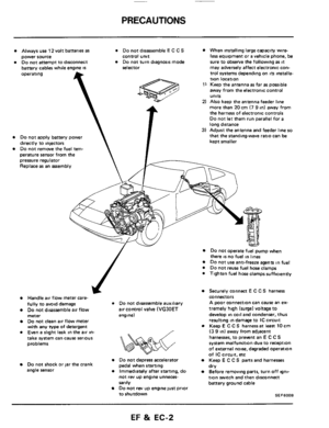
Caution
a. Before connecting or disconnecting E C C S
b
C
d
e
harness connector to or from any E C.C S.
unit, be sure to turn the ignition switch to the
"OFF" position and disconnect the negative
battery terminal
Otherwise, there may
be damage to control
unit
Do not attempt to disassemble any E C C S
component parts. To conduct electrical checks
on these component parts, closely follow the
steps outlined under "ELECTRONIC CON-
TROL SYSTEM INSPECTI0N"on pages EF
&
EC-43 through EF & EC-59.
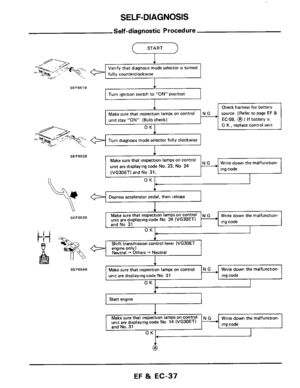
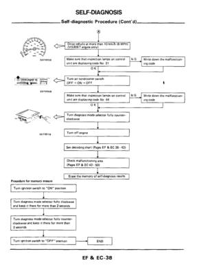
When conducting self-diagnosing, follow the
steps outlined under "SELF-DIAGNOSIS" on
pages EF
& EC-35 through EF & EC-42 in
order to obtain accurate diagnosing results
After selfdiagnosing has been completed, erase
the memory properly
Always turn the diagnosis mode selector care-
fully using
a screwdriver If it is turned forci-
bly,
it may be damaged, resulting in the inabili-
ty to perform the self-diagnosing or to monitor
the mixture ratio
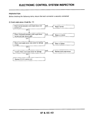
Before troubleshooting, ensure that
all harness
connectors are secure.
EF & EC-28
Page 29 of 79
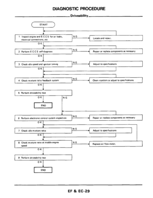
DIAGNOSTIC PROCEDURE
b NG 3 Check idle speed and ignition timing
Driveability
(--- START -l
Adjust to specifications
4 Check mixture ratio feedback system Clean injectors or adjust to specifications
I 5 Perform driveability test I
OK NG
Repair or replace components as necessary
P
6 Perform electronic control system inspection
OK I
Adjust to specifications
OK 1 I
NG 4-
7 Check idle mixture ratio
, I
I
Replace air flow meter. 8 Check mixture ratio at middle engine NG
speed
OK
) 9 Perform driveability test
EF & EC-29
Page 30 of 79
 Check all hoses and ducts for air leaks
2) Check air cleaner for clogging")
DIAGNOSTIC PROCEDURE
Driveabil
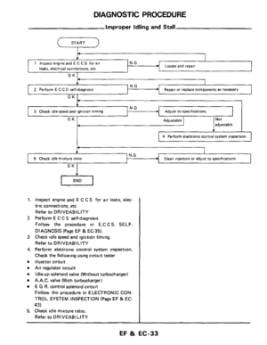
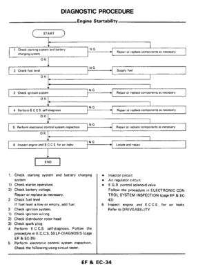
1. Inspect engine and E C C.S. for air leaks,
proper electrical connections, etc
1) Check all hoses and ducts for air leaks
2) Check air cleaner for clogging
3) Check harness connectors for proper connec-
tions
4) Check ignition wiring
5) Check gaskets for leaks at all air intake com-
ponents
6) Check E G.R valve operation
7) Check air regulator operation
2 Perform E C C S self-diagnosis
Follow the procedure in E CCS SELF-
DIAGNOSIS (Page EF & EC-35)
3 Check idle speed and ignition timing
a. Prepare the following conditions:
Headlampswitch' OFF
Heater blower: OFF
Air conditioner switch: OFF
Front wheel (Power steering model):
KEEP STRAIGHT AHEAD
b. Warm engine to operating temperature.
Check
and adjust as follows
[VG30E engine (Without turbocharger)]
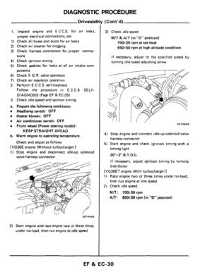
1) Stop engine and disconnect idle-up solenoid
valve harness connector
Idle-up solenoid
2) Start engine and race engine two or three times
under no-load, then run engine
at idle speed
(Cont'd)
3) Check idle speed
M/T & A/T (in "D" position)
700250 rpm at sea level
650250 rpm at high altitude condition
If necessary, adjust to the specified
speed by
turning idle speed adjusting screw
I, SEF6456
4) Stop engine and connect idle-up solenoid valve
harness connector
5) Start engine and check ignition timing with
a
timing light
20ai2" B.T.D.C.
If necessary, adjust ignition
timing by turning
distributor
[VG30ET engine (With turbocharger)]
1) Race engine two or three times under no-load,
then run engine at idle speed
2) Check idle speed.
M/T: 70W50rpm
A/T: 650k50 rpm (in "D" position)
EF & EC-30
Page 31 of 79

DIAGNOSTIC PROCEDURE
Driveabili
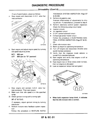
If out of specification, adjust as follows
ness connector
a Stop engine and disconnect A A C valve har-
SEF646B
b Start engine and adjust engine speed by turning
idle speed adjusting screw
M/T: 650 rpm
A/T. 600 rpm (in "D" position)
c. Stop engine and connect A.A.C. valve har-
ness connector Then
start engine
d Make sure that idle speed
is in the specified
range.
3) Check ignition timing with a timing light
ZO"r2" B.T.D.C.
If necessary, adjust ignition timing by turning
distributor
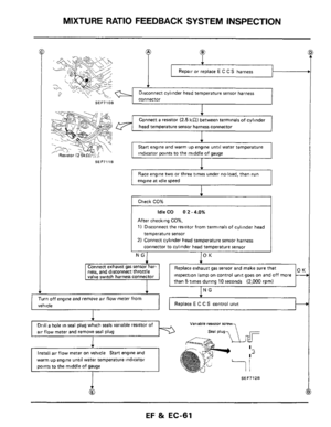
Perform mixture ratio feedback
system inspec-
tion Follow the procedure
in MIXTURE RATIO
4
(Cont'd)
FEEDBACK SYSTEM INSPECTION (Page EF
lk EC-60)
5 Perform driveability test
Evaluate effectiveness of adjustments by driv-
ing vehicle If unsatisfactory, proceed to step
6
6
Perform electronic control system inspection
Check the following using circuit tester
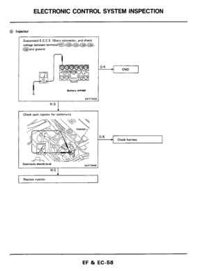
Injector circuits
Air regulator circuit
E G R control solenoid circuit
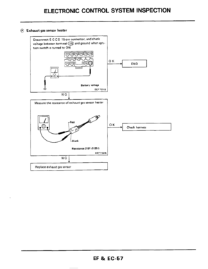
E xhaust gas sensor heater circuit
Follow the procedure in ELECTRONIC CON-
TROL SYSTEM INSPECTION (Page EF
& EC-
43)
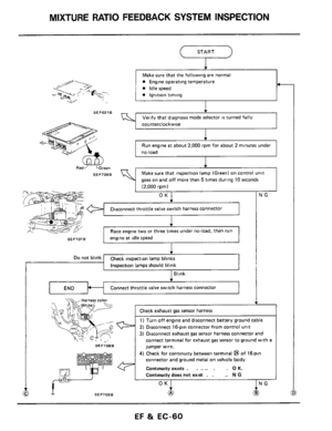
7 Check idle mixture ratio
1) Warm up engine to operating temperature
2) Turn off engine and disconnect throttle valve
switch harness connector
3) Verify that the diagnosis mode selector is
turned fully counterclockwise
4) Start engine and verify that engine IS still at
operating temperature.
5) Race engine two or three times under no-load,
then run engine
at idle speed
6) Look at inspection lamps (red and green)
SEF648B
When both inspection lamps blink, it indicates
that the idle mixture ratio IS correct.
EF & EC-31
Page 32 of 79
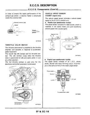
DIAGNOSTIC PROCEDURE
Driveability (Cont'd)
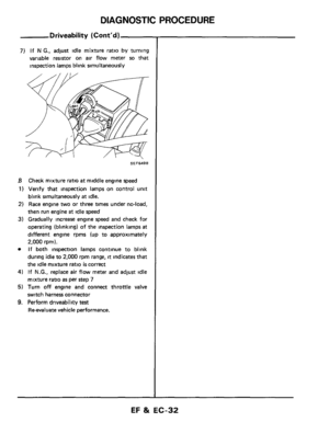
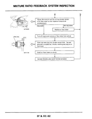
7) If N G., adjust idle mixture ratio by turning
variable resistor on
air flow meter so that
inspection lamps blink simultaneously
SEF649B
B Check mixture ratio at middle engine speed
1) Verify that inspection lamps on control unit
blink simultaneously at idle.
2) Race engine two or three times under no-load,
then run engine
at idle speed
3) Gradually increase engine speed and check for
operating (blinking)
of the inspection lamps at
different engine rpms (up to approximately
2,000 rprn).
If both inspection lamps continue to blink
during idle to
2,000 rpm range, it indicates that
the idle mixture ratio is correct
4) If N.G., replace air flow meter and adjust idle
mixture ratio
as per step 7
5) Turn off engine and connect throttle valve
switch harness connector
9. Perform driveability test
Reevaluate vehicle performance.
EF %t EC-32

Engine speed
Engine tem")


7) If N G., adjust idle mixture ratio by turning
variable resistor on
air flow meter so that
inspection lamps blink simultaneously
SEF649B
B Check")