Page 49 of 79
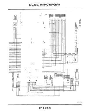
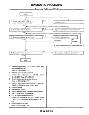
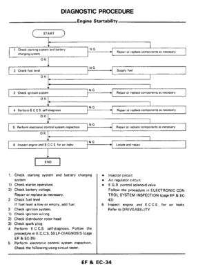
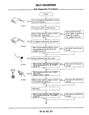
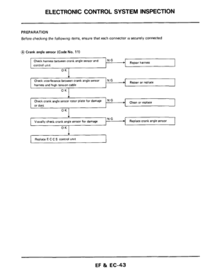
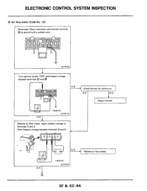
ELECTRONIC CONTROL SYSTEM INSPECTION
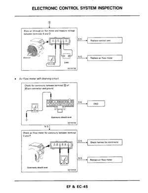
OK -+
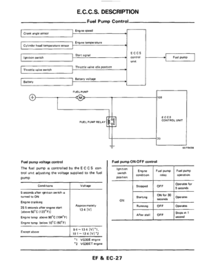
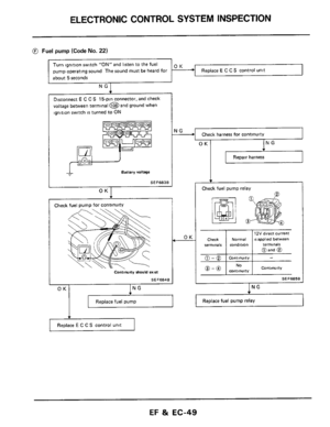
@ Fuel pump (Code No. 22)
Replace E C C S control unit
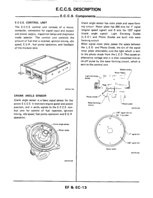
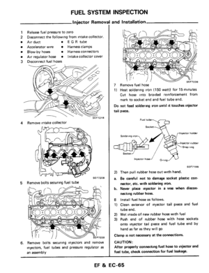
Turn ignition switch "ON" and listen to the fuel
pump operating sound The sound must be heard for
about
5 seconds
Check Normal
12V direct current
18 applied between ~
Disconnect E C C S 15-pin
connector. and check
voltage between terminal
@ and ground when
ignition switch
is turned to ON
Replace fuel pump
Battery voltage
SEF683B
OK I
Replace fuel pump relay
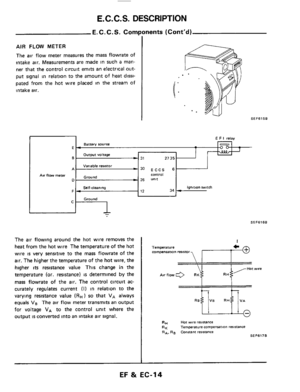
Check fuel pump for ContinuitY
Contmuny should exis
SEF684B
OK1 ING
Check harness for continuity
OK I ING
I Repair harness
OK
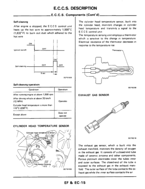
Check fuel pump relay
NO @ - @ I C0"tl""ltY
SEF685B
ING
EF & EC-49
Page 50 of 79
ELECTRONIC CONTROL SYSTEM INSPECTION
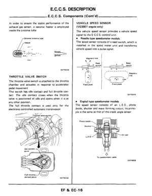
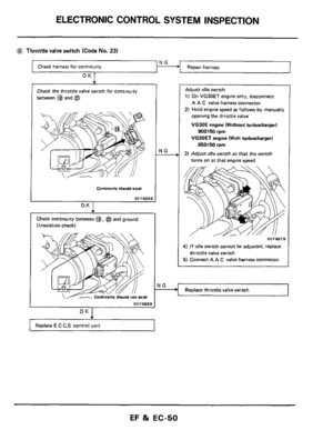
@ Throttle valve switch (Code No. 23)
Check harness for continuity
OK 1
Check the throttle valve switch for continuity
between
@ and @
Continuitv should exin
SEF686B
0.K I
Check continuity between @, @$ and ground
(Insulation check)
SEF6888
+
Replace E C C.S control unit
rlG
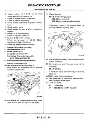
Adjust idle switch
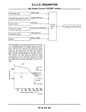
1) On VG30ET engine only, disconnect
A A C
valve harness connector
2) Hold engine speed as follows by manually
opening the throttle
valve
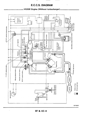
VG30E engine (Without turbocharger)
VG30ET engine (With turbocharger)
3) Adfust idle switch so that the switch
900+50 rpm
850*50 rpm
turns on at that engine speed
SEF687B
1) If idle switch cannot be adjusted, replace
5) Connect A A C valve harness connector
throttle valve switch
Replace throttle valve switch
EF 81 EC-50
Page 51 of 79
ELECTRONIC CONTROL SYSTEM INSPECTION
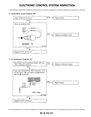
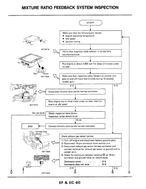
Start engine, turn air conditioner switch "ON" and
check compressor operation
@! NeutraVPark switch (Code No. 24)
N G + Check air conditioner system
Check harness for continuity F.1 Repair harness
OK I
NG -
Check neutrallpark swltch
Repair harness
Press I)
Free INeutrall 057 press IOtherrl -57 SEC764
OK I
Replace neutrallpark switch
I"
Replace E C C S control unit
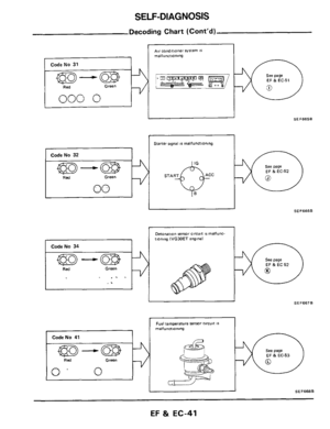
0 Air condttloner (Code No. 31)
Stop engine and disconnect 16-pin connector Turn
ignition switch
"ON" and measure voltage between
terminal
@ and ground
I Battery voltage
SEF690B
OK I
+
Replace E C C S control unit
EF & EC-51
Page 52 of 79
ELECTRONIC CONTROL SYSTEM INSPECTION
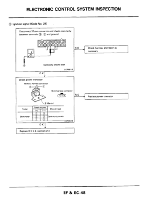
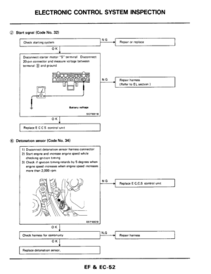
@ Start signal (Code No. 32)
Repair or replace NG Check starting system 1
OK
20-pin connector and measure voltage between
terminal and ground
Emery voltage
SE F691 B I OK I
Replace E C C S control unit
@ Detonation sensor (Code No. 34)
1 ) Disconnect detonation sensor harness connector
2)
Start engine and increase engine speed while
checking ignition timing
3) Check if ignition timing retards by 5 degrees when
engine speed increases when engine speed increases
more than 2,000 rpm
I SEF692B
Repair harness
(Refer to
EL section I
Replace E C.C.S control unit
Repair harness N.G OK1
Replace detonation sensor.
EF & EC-52
Page 53 of 79
ELECTRONIC CONTROL SYSTEM INSPECTION
Replace E C C S control unit
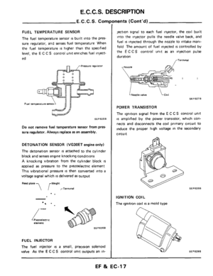
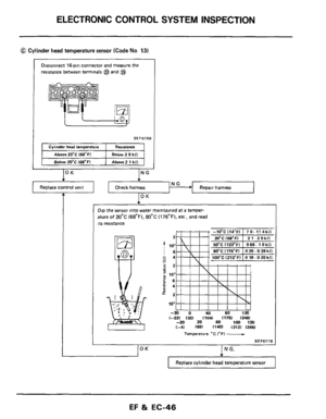
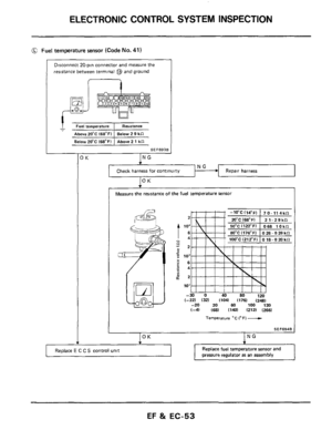
Fuel temperature sensor (Code No. 41)
Replace fuel temperature sensor and
Disconnect 20-pin connector and measure the
resistance between terminal
@ and ground
Fuel temperature I Resirlance
Above20'C 168'Fl I Below 2 9 kC
Below 2O:C 168"FI Above 2 1 kC1
-
SEF693B
Repair harness 1
Measure the resistance of the fuel temperature sensol
i c3425 2
1 '"
-
- :2
2 - ? 103
i6
-24 Y
t+2
10'
-30 0 40 80 1M (-221 (321 (1041 (1761 (248) -20 20 60 100 130 1-41 (681 (1401 12121 (2661
Temperarure 'c 1°F) -
EF %I EC-53
Page 54 of 79
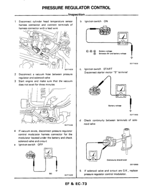
ELECTRONIC CONTROL SYSTEM INSPECTION
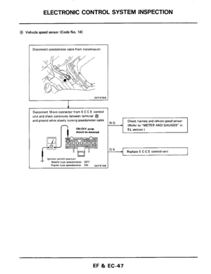
Check harness ~~
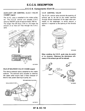
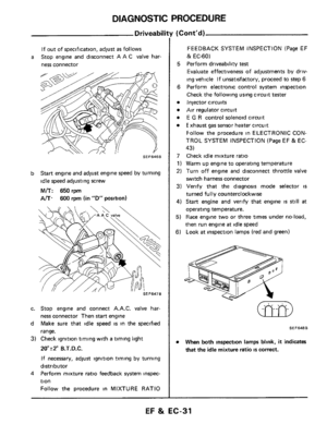
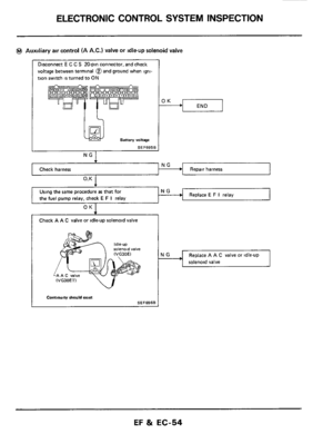
@ Auxiliary
air control (A A.C.) valve or idleup solenoid valve
Repair harness
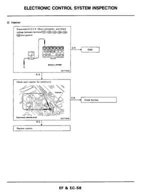
Disconnect E C C S 20-pin connector, and check
voltage between terminal @and ground when igni-
tion switch
is turned to ON
LEU Battery voltage
I SEF695B
NG I
Replace E F I relay the fuel pump relay. check E F I relay I
OK I
Check A A C valve or idle-up solenoid valve
Replace A A C valve or idle-up
solenoid valve
I
EF & EC-54
Page 55 of 79
ELECTRONIC CONTROL SYSTEM INSPECTION
NG Check harness for continuity c
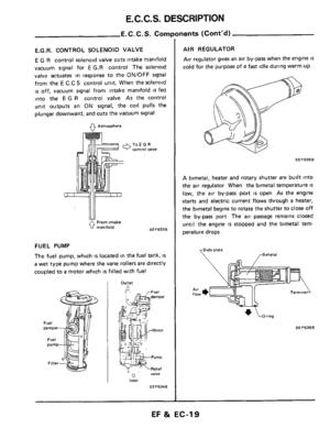
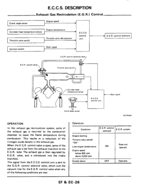
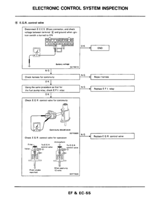
@ E.G.R. control valve
Disconnect E C C S 20-pin connector, and check
voltage between terminal @and ground when igni-
tion switch
is turned to ON
Repair harness
Battery voltage
SEF697B
NG
Using the same procedure as that for
the fuel pump relay, check
E F I relay
NG Replace E F I relay
Check E G R control valve for continuity
m
SEF6988
Check E G R control valve for operation
Armorohere
0 From intake
R ".I". d ToEGR Control Valve
When applying 12 "Oltl manifold SEF79ZB
NG - Replace E G R control valve
EF & EC-55
Page 56 of 79
ELECTRONIC CONTROL SYSTEM INSPECTION
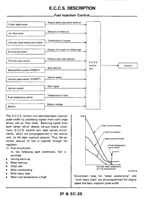
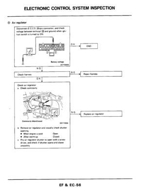
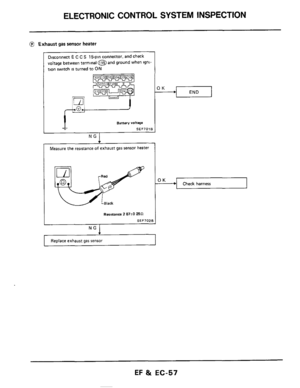
@ Air regulator
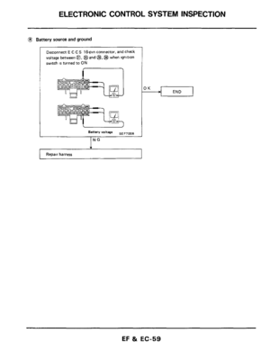
Disconnect E C C S 20-pin connector, and check
voltage between terminal @and ground when igni-
tion switch
is turned to ON
I I
Battery "Dltage
SEF699E
NG I
Check harness . Repair harness
Check air regulator
a Check continuity
I
Continuiry should enst SEF700B
b Remove air regulator and visually check shutter
opening.
0 When engine is cold Open
0 After warm-up Closed
c Pry air regulator shutter to open with a screw-
driver, and check
if shutter opens and closes
smoothly
I
Replace air regulator
EF & EC-56

Replace E C C S control unit
Turn ignition switch \"ON\" and listen to the fuel
pump operating sound The sound must be h")

Check harness for continuity
OK 1
Check the throttle valve switch for continuity
between
@ and @
Continuitv should e")

N G + Check air conditioner system
Chec")

Repair or replace NG Check starting system 1
OK
20-pin connector and measure voltage between
terminal and ground
Emery volt")

Replace fuel temperature sensor and
Disconnect 20-pin connector and measure the
resist")
 valve or idleup solenoid valve
Repair harness
Disconnect E C C S 20-pin connector, and check
voltage")

