Page 9 of 99
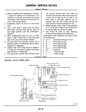
GENERAL SERVICE NOTICE
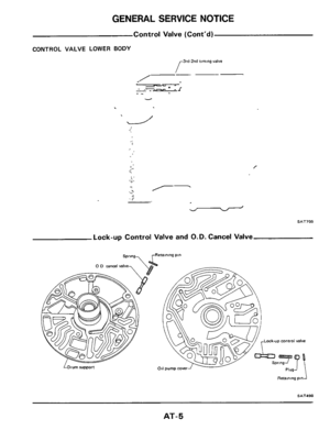
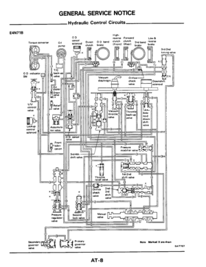
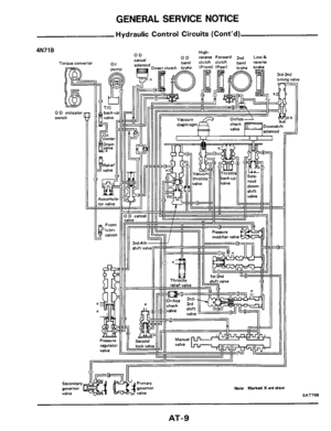
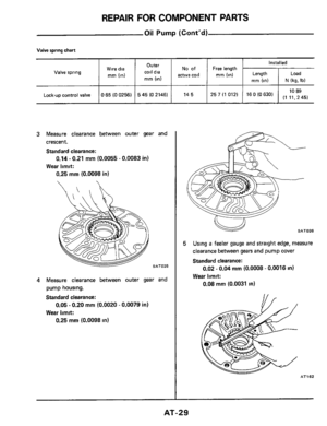
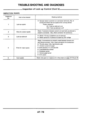
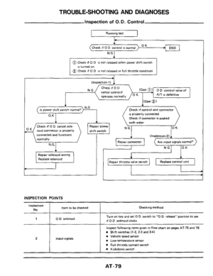
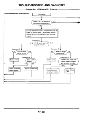
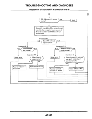
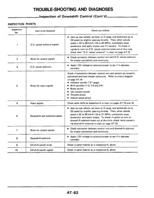
Hydraulic Control Circuits (Cont'd)
High- 0 D rwerse Forward 2"d Low& OD cancel
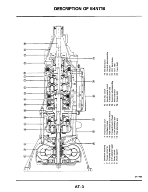
4N71B
Torque converter
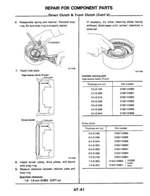
Note Marked X are dram
-
SAT708
AT-9
Page 10 of 99
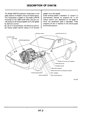
ON-VEHICLE SERVICE
Contrl
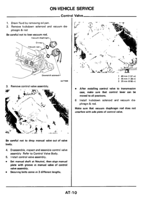
1. Drain fluid by removing oil pan.
2. Remove kickdown solenoid and vacuum dia
phragm
23 rod
Be careful not to lose vacuum rod.
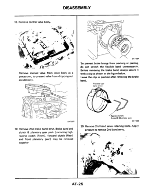
Vacuum diaphragm
SAT506
3. Remove control valve assembly.
Be careful not to drop manual valve out of valve
body.
4. Disassemble, inspect and assemble control valve
assembly Refer to Control Valve Body.
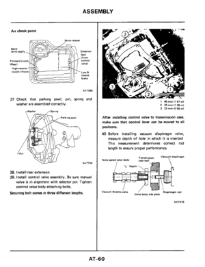
5. Install control valve assembly.
0 Set manual shaft at Neutral, then align manual
plate with groove in manual valve of control
valve assembly.
Securing bolts come
in 3 different lengths. 0
1 40 mm I1 51 in) 2 35 mm (1 38 in1 3 25mm1098mI
After installing control valve to transmission
case, make sure that control lever can be
moved to all positions.
6 Install kickdown solenoid and vacuum dia-
phragm
& rod.
Make sure that vacuum diaphragm rod does not
interfere with side plate
of control valve.
AT-I 0
Page 11 of 99
ON-VEHICLE SERVICE
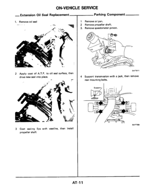
-Extension Oil Seal Replacement-
1. Remove oil seal
. -. .
2 Apply coat of A.T.F. to oil seal surface, then
drive new seal into place.
3 Coat sealing lips with vaseline, then install
propeller shaft
Parking Component
1 Remove oil pan.
2 Remove propeller shaft.
3. Remove speedometer pinion.
SAT51 1
4 Support transmlssion with a jack, then remove
rear mounting bolts.
AT-1 1
Page 12 of 99
-
5. Remove rear extension bolts, then draw out
rear extension with rear mounting.
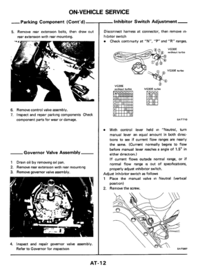
6. Remove control valve assembly.
7. Inspect and repai")
~ ~~ ON-VEHICLE
SERVICE
-Parking Component (Cont'd)-
5. Remove rear extension bolts, then draw out
rear extension with rear mounting.
6. Remove control valve assembly.
7. Inspect and repair parking components Check
component
parts for wear or damage.
-Governor Valve Assembly
1 Drain oil by removing oil pan.
2. Remove rear extension with rear mounting
3. Remove governor valve assembly.
4. Inspect and repair governor valve assembly.
Refer to Governor for inspection
-Inhibitor Switch Adjustment-
Disconnect harness at connector, then remove in-
hibitor switch
Check continuity at "N", "F'" and "R" ranges.
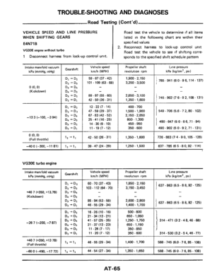
VG30E without turbo
VG30E turbo
VG30E wnhout turbo
0
VG30E turbo
SAT710
With control lever held in "Neutral, turn
manual lever
an equal amount in both direc-
tions to see
if current flow ranges are nearly
the same. (Current normally begins to flow
before manual lever reaches
a angle of 1.5" in
either direction.)
If current flows outside normal range, or if
normal flow range is out of specifications,
properly adjust inhibitor switch.
Adjust inhibitor switch as follows
1 Place the manual valve in Neutral (vertical
2. Remove the screw.
position)
AT-I 2
Page 13 of 99
ON-VEHICLE SERVICE
-Inhibitor Switch Adjustrnent-
(Cont'd)
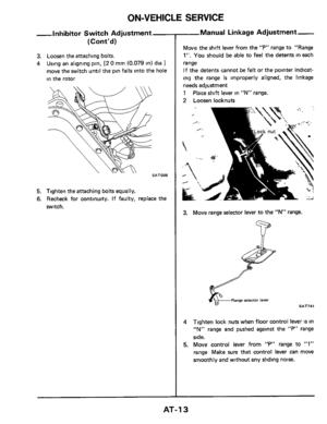
3. Loosen the attaching bolts.
4 Using an aligning pin, [2 0 mm (0.079 in) dia 1
move the switch until the pin falls into the hole
in the rotor
5. Tighten the attaching bolts equally.
6. Recheck for continuity. If faulty, replace the
switch.
--Manual Linkage Adjustrnent-
M,we the shift lever from the "P" range to "Range
1"'. You should be able to feel the detents in each
range
If the detents cannot be felt or the pointer indicat-
ing the range
is improperly aligned, the linkage
needs adjustment
1
2 Loosen locknuts
Place shift lever in "N" range.
3. Move range selector lever to the "N" range.
Range selector lever
SAT741
4 Tighten lock nuts when floor control lever IS in
"N" range and pushed against the "P" range
side.
5. Move control lever from "P" range to "1"
range Make sure that control lever can move
smoothly
and without any sliding noise.
AT-I 3
Page 14 of 99
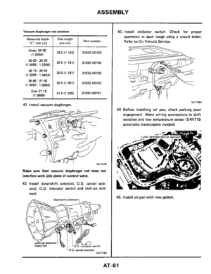
Vacuum Diaphragm Rod
Adjustment
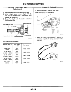
1. Remove diaphragm from transmission case.
2 Using a depth gauge, measure depth "L". Be
sure vacuum throttle valve is pushed into valve
body
as far as possible.
3 Check "L" depth with chart below and select
proper length rod.
Measured depth "L"
mm (in)
Under 25 55
(1 0059)
25 65
- 26 05
(1 0098
- 1 0256)
26 15
- 26 55
(1 0295 - 1 0453)
26 65
- 27 05
(1 0492 - 1 0650)
Over 27 15
(1 0689)
Vacuum diaphragm
Rod length
mm (in)
29 0
(1 142)
29 5
(1 161)
30
0
(1 181)
30 5
(1 201)
31
0
(1 220)
Vacuum diaphragm
I1
rod
SAT078
Part number
31932- X0103
31932 - XO104
31932- XOlOO
31932- X0102
31932. XOlOl
Downshift Solenoid
1. Remove downshift solenoid and O-ring.
Catch
oil dropping out of the hole.
SAT516
2 Check to verify that downshift solenoid is
operatmg properly. If faulty, replace it with a
new one
SAT517
AT-I4
Page 15 of 99
ON-VEHICLE SERVICE
Kickdown Switch Adjustment
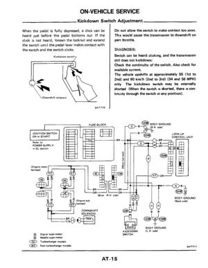
When the pedal is fully depressed, a click can be
heard just before the pedal bottoms out
If the
click
is not heard, loosen the locknut and extend
the switch until the pedal lever makes contact with
the switch and the switch clicks
Kickdown switch 7
F$i& Downshift solenold
qi& Downshift solenold
SAT719
Do not allow the switch to make contact too soon.
This would cause the transmission to downshift on
part throttle.
DIAGNOSIS:
Switch can be heard clicking, and the transmission
still does not kickdown:
Check the continuity of the switch.
Also check for
available current.
The vehicle upshifts
at approximately 55 (1st to
2nd) and
90 kmlh (2nd to 3rd) (34 and 56 MPH)
only The kickdown switch may be internally
shorted (When the switch
is shorted, there IS con-
tinuity through the switch in any position).
AT-I 5
Page 16 of 99
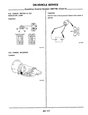
ON-VEHICLE SERVICE
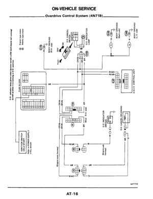
Overdrive Control System (4N71B)
I..
- a2 P
I
*
1
SAT712
AT-1 6
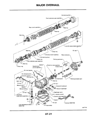


High- 0 D rwerse Forward 2\"d Low& OD cancel
4N71B
Torque converter
Note Marked X are dram
-
SAT708
AT-9")


3. Loosen the attaching bolts.
4 Using an aligning pin, [2 0 mm (0.079 in) dia 1
move the switch until the pin falls into the hole")


I..
- a2 P
I
*
1
SAT712
AT-1 6")