Page 89 of 99

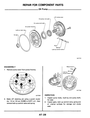
good condition?
Repair harness")
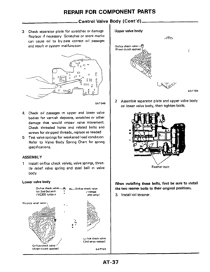
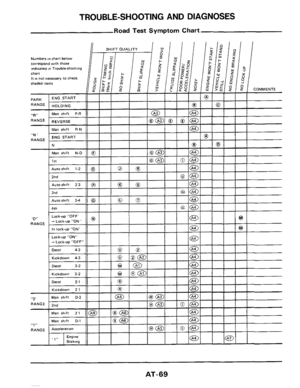
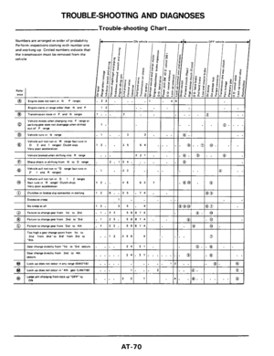
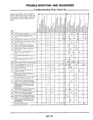
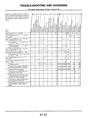
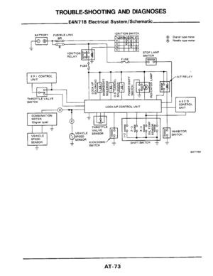
TROUBLE-SHOOTING AND DIAGNOSES
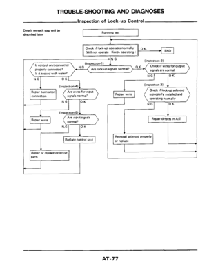
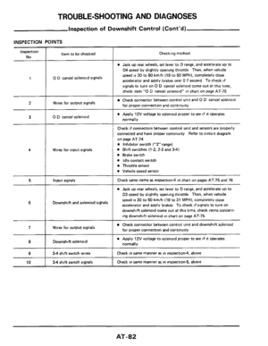
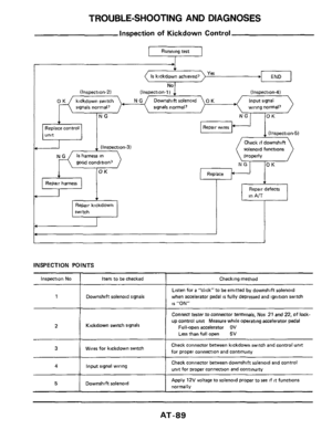
Inspection of Kickdown Control
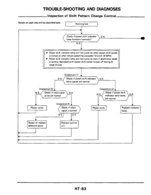
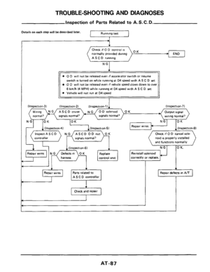
I Running test I
signals normal? signals normal? wiring normal?
Replace contrul
(I nspection-3)
good condition?
Repair harness
switch
I
Repair wires
(Inspection-5)
Check if downshift
solenoid functions
properly
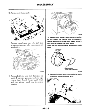
Replace
in A/T I I
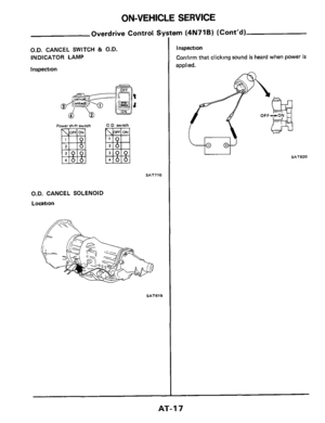
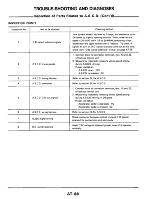
INSPECTION PO I NTS ~~
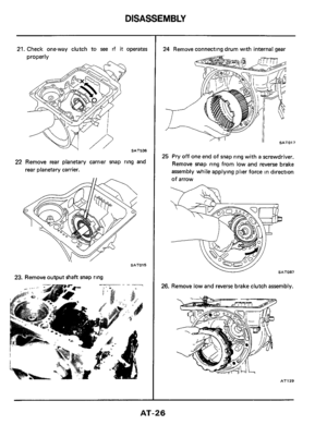
~
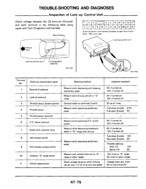
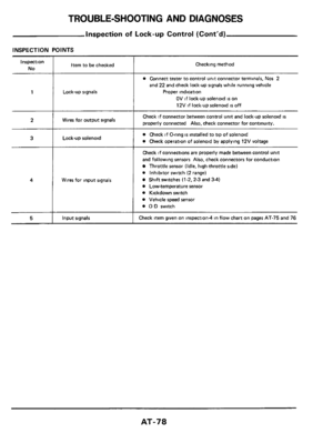
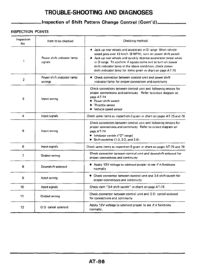
Inspection No Item to be checked Checking method
Listen for a “click“to be emitted by downshift solenoid
when accelerator pedal
is fully depressed and ignition switch
is “ON“
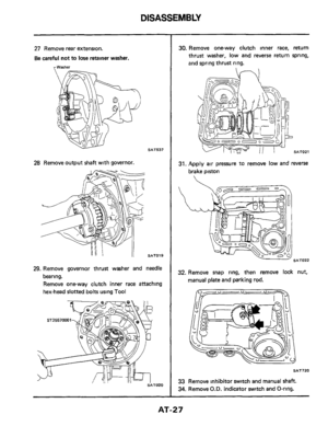
Downshift solenoid signals
I 1 Connect tester to connector terminals, Nus 21 and 22, of lock-
up control unit Measure while operating accelerator pedal
I Full-open accelerator OV 2 I Kickdown switch signals
Less than full open 5V
Check connector between kickdown switch and control unit
for moper connection and continuitv 3 1 Wires for kickdown switch
4 I Input signal wiring Check connector between downshift solenoid and control
unit for proper connection and continuity
Apply 12V voltage to solenoid proper to see if it functions
normally Downshift solenoid 5
AT-89
Page 90 of 99

TROUBLE-SHOOTING AND DIAGNOSES
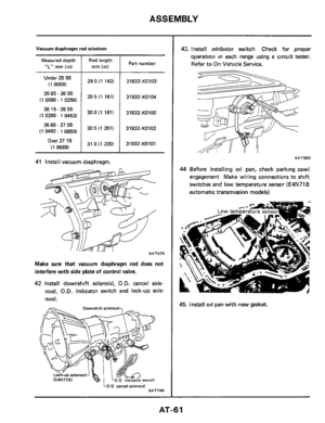
2
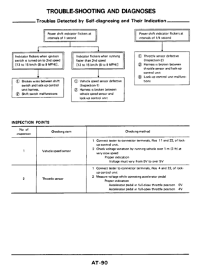
Troubles Detected by Self-diagnosing and Their Indication
Throttle sensor
I I
switch is turned on to 2nd speed
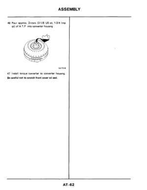
switch and lock-up control
unit harness.
faster than 2nd speed
0 Vehicle speed sensor defective
@ Harness is broken between
(Inspection-1)
vehicle speed sensor and
lock-up control unit
+
@ Throttle sensor defective
(Inspection.2)
@ Harness is broken between
throttle sensor and lock-up
control unit
@ Lock-up control unit malfunc-
tions
INSPECTION POINTS
Checking method No of
inspection Checking item
Vehicle speed sensor
1 Connect tester to connector terminals, Nos 11 and 22, of lock-
up control unit.
2 Check voltage variation by running vehicle over 1
m (3 ftl at
very slow speed
Proper indication
Voltage must vary from OV to over 5V
1
1 Connect tester to connector terminals. Nos 4 and 22, of lock-
up control unit
2 Measure voltage while operating accelerator pedal
Proper indication
Accelerator pedal in fullclose throttle position OV
Accelerator pedal in full-open throttle position 4V
AT-90
Page 91 of 99

SAT765
1
2 Warm up engine until e")
TROUBLE-SHOOTING AND DIAGNOSES
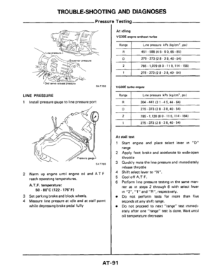
Pressure Testing ~ ~~
2
LINE PRESSURE
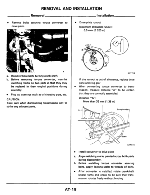
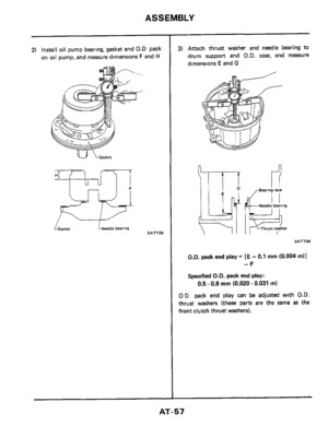
1 Install
pressure gauge to line pressure port
785 - 1,128 (8 0- 11 5, 114- 164)
SAT765
1
2 Warm up engine until engine oil and AT F
reach operating temperatures.
A.T.F. temperature:
3 Set parking brake and block wheels.
4 Measure line pressure at idle and at stall point
while depressing brake pedal
fully
50 ~ 80°C (122 - 176°F)
275 - 373 (2 8.3 8.40.54)
At idling
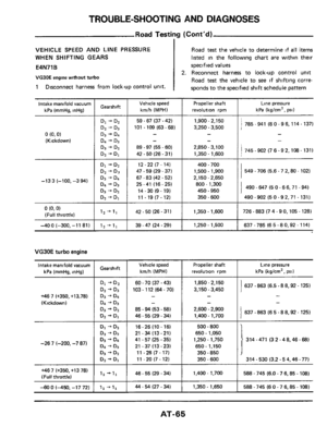
VG90E engine without turbo
Range 1 Line pressure kPa (kg/crn2. psi)
R I 451 -588(46-60,65-85)
D 1 275-373(28-38.40-54)
2 I 785.1,079 (80- 11 0,114- 156)
1 1 275-373(28-38.40-54)
VG3OE turbo engine
Range Line pressure kPa (kg/cm2, psi)
304-441 (31-45.44-64)
275
- 373 (2 8.38.40.54)
At stall test
1 Start engine and place select lever in "D"
range
2 Apply foot brake and accelerate to wide-open
throttle
3 Quickly note the line pressure and immediately
release throttle
4 Shift select lever to "N".
5 Cool off A.T F.
6 Perform line pressure testing in the same man-
ner as in steps 2 through 6 with select lever
in
"2". "1" and "R", respectively.
Do not perform tests for more than five
seconds
at any shift range.
Do not proceed to next "range" test imrnedi-
ately after one "range"
test is done. Wait until
oil temperature decreases
AT-91
Page 92 of 99

Intake manifold
vacuum
kPa (mmHg,
inHsl
VG30E engine without turbo
Propeller $haft
Vehicle speed revolutions
kmlh (MPH)
rpm
Ran")
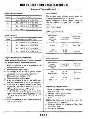
TROUBLE-SHOOTING AND DIAGNOSES
Pressure Testing (Cont'd)
Intake manifold
vacuum
kPa (mmHg,
inHsl
VG30E engine without turbo
Propeller $haft
Vehicle speed revolutions
kmlh (MPH)
rpm
Range I Line pressure kPa (kglcm', psi)
Intake manifold
vacuum
kPa (mrnHg.
inHg) ~
R I 1,961 - 2,393
(20 0.24 4,284 .347)
Propeller shaft Vehicle speed
kmlh (MPH) revolutions
rpm
D I 1.079-1,226(110-125,156-178)
2 I 1,079 - 1,275 (11 0.13 0, 156 - 185)
1 I 1,079 - 1,226 (1 1 0 - 12 5, 156 - 178)
VG30E turbo engine
Range I Line pressure kPa (kgtcm', psi)
R I 1,961 - 2,354 (20 0 - 24 0,284 - 341)
D I 1,667 - 1,883 (17 0- 19 2,242 -273)
2 I 1.667-1,883(170-192,242-273)
1 I 1.667-1.8831170-192.242-273)
Judgment by measuring line pressure
If line pressure does not rise, first check to make
sure that vacuum
hose is connected properly.
1) When line pressure is low at all positions, the
problem may be due to
Wear on interior of oil pump
Oil leakage at or around oil pump, control
valve body, transmission case or governor
Sticking pressure regulator valve
Sticking pressure modifier valve
2) When line pressure is low at a particular posi-
tion, the problem may be due to the following
If oil leaks at or around forward clutch (rear)
or governor, line pressure
is low in "D", "2" or
"1" range but is normal in "R" range.
If oil leaks at or around low and reverse brake
circuit, line pressure becomes low in
"R" or
"P" range but IS normal in "D", "2" or "1"
range.
3) When line pressure is high, pressure regulator
valve may have stuck
Cutdown point
The cut-down point indicates
a point where line
pressure changes from high to low value.
Before proceeding cut-down testing, make sure
that line pressure "At Idle" and "At
Stall'' is
normal
Install vacuum gauge
VG30E engine without turbo
28 - 37
o(o'o) I (17-231 I 900- 1,200
12.22
(7 - 14) I 400-700 (-100. -133 -3 94) I
VG30E turbo engine
+467 I 29 - 39 1,200- 1,600 (+350, +13 78) (18 - 24)
13.23
(-200,
-267 -7 871 I (8. 14) 400 - 800
Judgment by cut-down testing
(1) When cut-down point disappears, the problem
Sticking pressure modifier valve
Sticking governor valve
Oil leaks at oil passage
(2) When cut-down point is too low or too high,
the problem may be due to
Incorrect springs (at pressure modifier valve
or governor valve)
Oil leaks at oil passage
may be due to
AT-92
Page 93 of 99

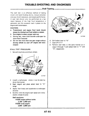
TROUBLE-SHOOTING AND DIAGNOSES
Stall
The stall test is an effective method of testing
clutch and band holding ability, torque converter
one-way clutch operation, and engine performance
A
stall test should only be performed as a last
resort because of the high fluid temperature it
generates and the excessive load it places on the
engine and transmission.
CAUTION:
a. Transmission and engine fluid levels should
b
c.
d
always be checked and fluid added as needed.
Run engine to
attain proper warm-up.
During test, never
hold throttle wide-open for
more than
5 seconds
Do not test more than two gear ranges without
driving vehicle to
cool off engine and trans-
mission
STALL TEST PROCEDURE
1 Set parking brake and block wheels
SAT597
2 Install a tachometer where it can be seen by
driver during
test
3 Start engine and place select lever in "D"
range
4 Apply foot brake and accelerate to wide-open
throttle
5 Quickly note the engine stall speed and imme-
diately release throttle
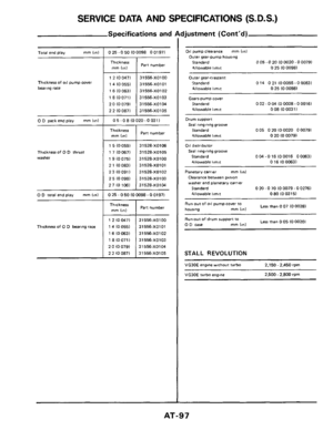
Stall revolution:
VG30E engine without turbo
VG30E turbo engine
2,150 - 2,450 rpm
2,500 - 2,800 rpm
SAT598
6
7 CooloffAT F
8 Perform stall tests in the same manner as in
steps 3 through 7 with select lever in "1" and
"R", respectively
Shift select lever to "N"
AT-93
Page 94 of 99
TROUBLE-SHOOTING AND DIAGNOSES
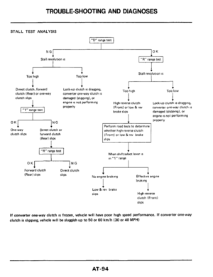
STALL TEST ANALYSIS
“D range test
NG OK
Stall revolution is
I
1 Too low 4 1 Too high Lock-up clutch is dragging,
converter one-way clutch
is
engine is not performing
properly
4 Direct clutch, forward
clutch (Rear) or one-way
clutch slips damaged (shpping), or
Lock-up clutch is dragging.
convener one-way clutch
is
engine is not performing
properly
I High-reverse clutch
(Front) or low
& rev
brake slips damaged (slipping), or
whether high-reverse clutch
(Front) or low &rev brake
OK NG
One-way Direct clutch or
clutch slips forward clutch
(Rear) slips
When shift select lever IS
In “1” range
OK
No engine braking Effective engine (Rear) slips slips
braking
I
High-reverse
clutch (Front)
slips
Low & rev brake
slips
If converter one-way clutch is frozen, vehicle will have poor high speed performance. If converter one-way
clutch
is slipping, vehlcle will be sluggish up to 50 or 60 kmlh (30 or 40 MPH)
AT-94
Page 95 of 99

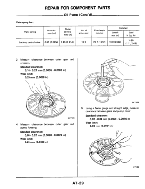
General Specifications
X8075 Engine model ~ I VG30E t VG30Eiurbo X8006 -
Autamatictranrmirrion model I E4N71B I 4N71B ~~
Stall torque ratlo
Transmission")
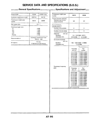
SERVICE DATA AND SPECIFICATIONS (S.D.S.)
General Specifications
X8075 Engine model ~ I VG30E t VG30Eiurbo X8006 -
Autamatictranrmirrion model I E4N71B I 4N71B ~~
Stall torque ratlo
Transmission gear ratio
1st
2nd
TOP OD
Reverse
Recommended 011
1 X8075 1 X8006 Tianrmwon model code
number ~
20 1
2 458
1458
1000
0 686
2 182
Aurornar~c lranmwon fluid 'oexro" type
2 0 IO 0791
Oil capacity
2 2 (0 0871
7 0 hferr
17-3/8 US qt, 6-1/8 Imp qtl
5 6 (0 220)
5 8 (0 2281
6 0 (0 2361 6 2 IO 2441
6 4 10 2521
6 6 10 2601 6 8 (0 2681
7 0 (0 2761
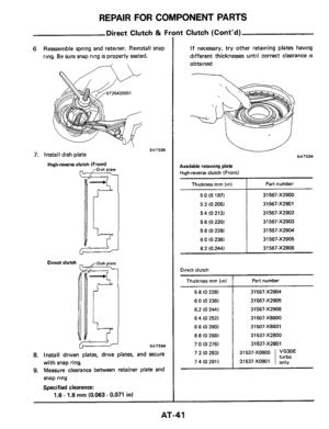
--Specifications and Adjustment,
31567-XZ903
31567-XZ904
31567-XZ905
31567-XZ906
31507-X86W
31507-X8601
31537-XZ800
31537-XZ801
Tr.msmirrmn model code number
Torque converter assembly
Srarnped mark on the
torque COnYerter
Number of drive plates
Number of driven plates
Clearance rnm Ion1
Standard Allowable limit
Drive plate thickness mm (in1
Standard
Allowable limit
Thlcknesr of retamng
Dlate
1 GC GK
1 50 1 65 (0 0591 .O 06501
1 4 (0 0551
Thickness I numbel Part
mrn Iml
Thickness number
AT-95
Page 96 of 99

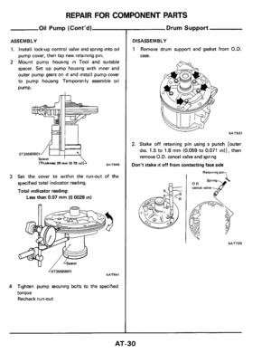
Specifications and Adjustment (Cont’d)
X8075 X8075
7:
X8W6 Transmission model
code number
2 2 (0 0871
Transmission model code
number
2410oM) 2 0")
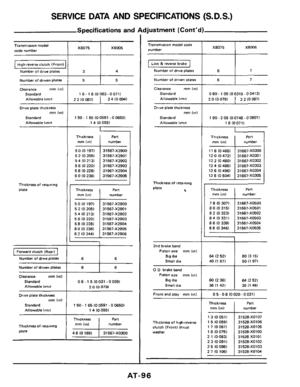
SERVICE DATA AND SPECIFICATIONS (S.D.S.)
Specifications and Adjustment (Cont’d)
X8075 X8075
7:
X8W6 Transmission model
code number
2 2 (0 0871
Transmission model code
number
2410oM) 2 0 IO 0791 2 2 (0 087)
I Low & reverse brake I Hbgh-reverse clutch IFrontl
Number of drive plates Number of drive plates
Number
of driven plates
Clearance mm (in)
Standard Allowable limit
Drive plate thickness
mm (in1
Standard
Allowable limit
Clearance mm (1n1
Standard
Allowable limit
Drive plate thickness mm (in)
Standard
Allowable I,mlt 1 50 - 1 65 (0 0591 .O 06501
1 4 (0 0551 190 -205 (00748 -00807)
18 (00711
1
mm Iml number
11 8 (0 4651 31667-XO3W
12 0 (0 4721 31667-XO301
12
2 (0 4801 31667-XO302
12 4
IO 4881 31667-XO303
12
6 IO 4961 31667-XO304
12
t 8 (0 5041 31667-XO305
Thickness Thickness
mm ItnI number
Thickness of retaining
plate h
Thickness of retaning
Plate Pan
number
Thickness mm lml number Thickness
mm Iinl
5 0 10 1971
5 2
10 2051
5 4 IO 2131
5 6 (0 2201 5 8 IO 2281
6 0 IO 2361
6210244)
31567-XZ900
31567-XZ901
31567-XZ902
31567-XZ903
31567-X2904
31567-XZ905
31567-XZ906
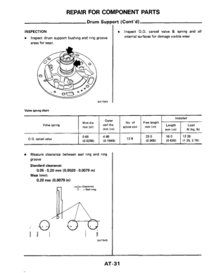
2nd brake band
Pinon size mm Inn1
Big dta Small dia
0 D brake band
Pinon size mm (in)
Btg dia
Small dia
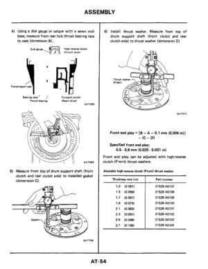
Front end play mm (in1
Forward clutch (Rear1
Number of drwe plates 64 (2 521 80 13 151
60 (2 361
36 (1 421 €4 (2 521
36 (1
461
Number of driven plate6 6 I 6
Clearance mm (an1
Standard
Allowable limit
Drive plate thickness mrn IinI
Standard
Allowable
limit
08- 1 5 I0031 .00591
2 0 IO 0791
0 5 - 0 8 IO 020 - 0 0311
1 50 - 1 65 10 0591 .O 06501 1 4 IO 0551
Thickness mm (on1
13 I00511
1 5 IO 0591 1 7 (0 0671
1
9 IO 0751
2 1 (0 0831
23100911
2 5 IO 0981 2 7 (0 1061
Pan number
31528-XO107
31 528-XO106
31 528-XOlO5
31528-XOlOO
31528 XOlOl
31 528-X0102
31 528-XO103
31 528-X01M Part I number Thicknerr mm (14 Thickness of hlgh-reverse
clutch (Front) thrust
washer Thickness of retaining
plate
48 (0 1891 I 31567-XO300
AT-96