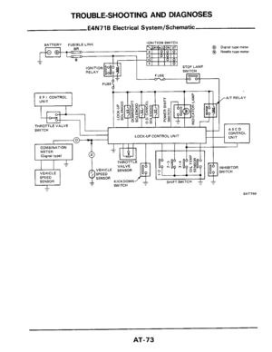
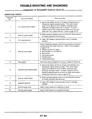
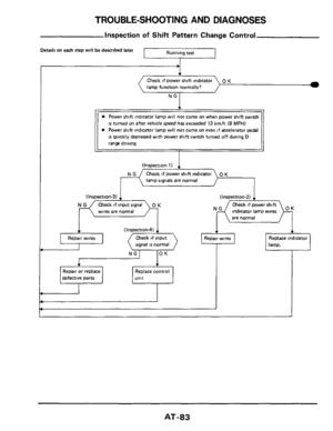
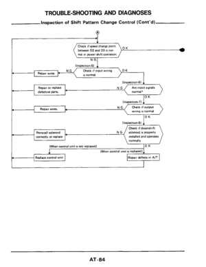
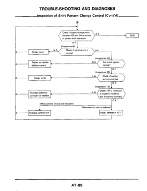
Page 17 of 99
ON-VEHICLE SERVICE
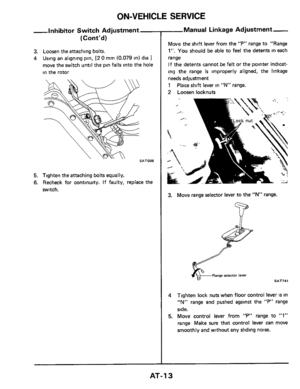
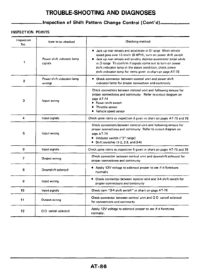
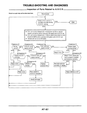
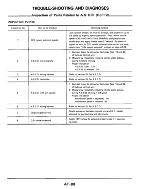
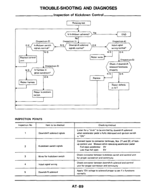
Overdrive Control Sy:
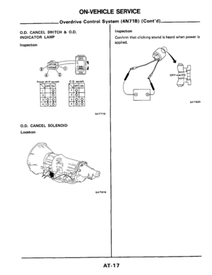
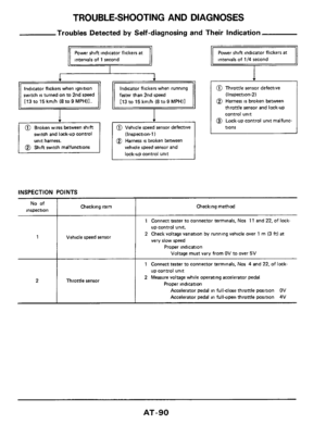
O.D. CANCEL SWITCH 81 O.D.
INDICATOR LAMP
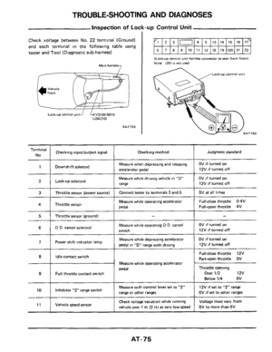
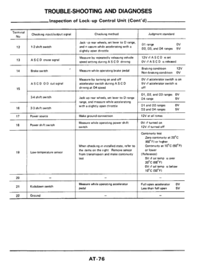
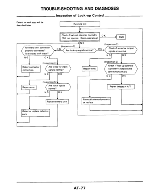
Inspection
Power shift switch
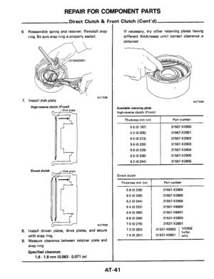
SAT716
O.D. CANCEL SOLENOID
Location
SAT619
?m (4N71B) (Cont'd)
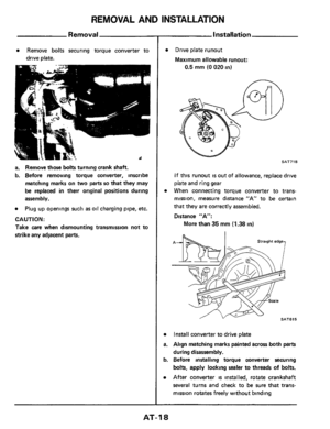
Inspection
Confirm that clicking sound
is heard when power is
applied.
w SAT620
AT-I 7
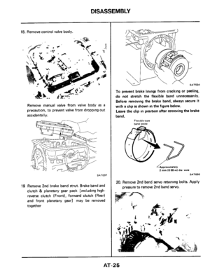
Page 18 of 99

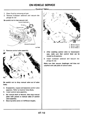
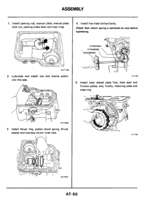
REMOVAL AND INSTALLATION
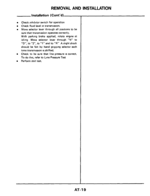
Removal
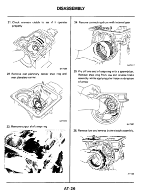
a Remove bolts securing torque converter to
drive plate.
a. Remove those bolts turning crank shaft.
b. Before removing torque converter, inscribe
matching marks on
two parts so that they may
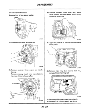
be replaced in their original positions during
assembly.
a Plug up openings such as oil charging pipe, etc.
CAUTl ON :
Take care when dismounting transmission not to
strike any adjacent
parts.
Installation
0
a
a.
b.
a
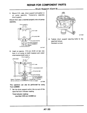
Drive plate runout
Maximum allowable runout:
0.5 mm (0 020 in)
n
SAT718
If this runout is out of allowance, replace drive
plate and ring gear
When connecting torque converter to trans-
mission, measure distance "A" to be certain
that they are correctly assembled.
Distance "A":
More than
35 mm (1.38 in)
Install converter to drive plate
Align matching marks painted across both parts
during disassembly.
Before installing torque converter securing
bolts, apply locking sealer to threads
of bolts.
After converter is installed, rotate crankshaft
several turns and check to be sure that trans-
mission rotates freely without binding
AT-I 8
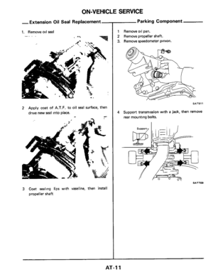
Page 19 of 99
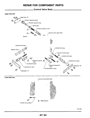
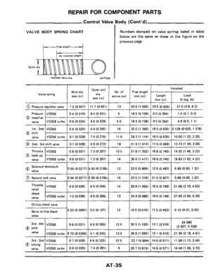
REMOVAL AND INSTALLATION
installation (Cont'd)
Check inhibitor switch for operation
Check fluid level
in transmission.
Move selector lever through
all positions to be
sure that transmission operates correctly.
With parking brake applied, rotate engine
at
idling Move selector lever through "N" to
"D", to "2". to "1" and to "R" A slight shock
should
be felt by hand gripping selector each
time transmission
is shifted.
Check to be sure
that line pressure is correct.
To do this, refer to Line Pressure Test
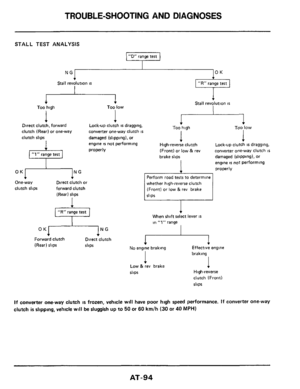
Perform stall test.
AT-I 9,
Page 20 of 99
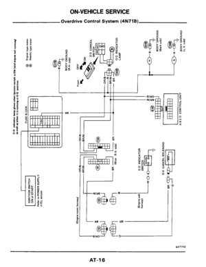
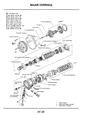
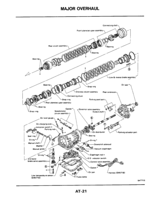
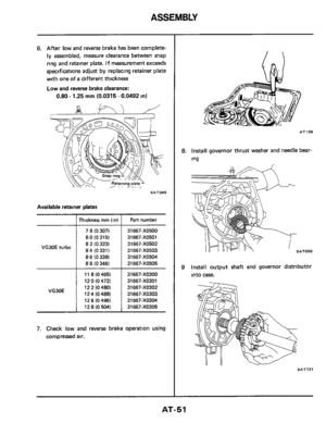
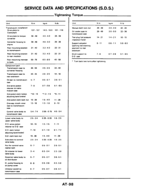
MAJOR OVERHAUL
N rn 1kg-m. ft-lb)
@ 39 49140-50.29-361
@ 10- 15110- 15.7-11) @ 44.54 14 5 - 5 5,33 -401
@ 13 18113-1.8.9-13)
011 pump assembly & 5 -7 (05 -07.36.5 1) @ 8- 11 (08- 1.1,58-80)
@ 7 -9 (07 -0 9,5 1 -65)
@I 5 4 - 7 4 10.55 - 0 75,4 0 - 5 4)
@ 5.7 105 -0.7,36 - 5 1) @ 29 39130-40.22-29)
O-ring (E4N71B)'
Converter housing
0 D planetary gear assembly
/
/ Connectmg shell-,
lbp&y ) ,,,rLOck*pcontrol solenotd /~ brakeband , /Thrust washer *-
, /Gasket *
Lathe cut seal Tin& 7
\Thrust washer t
2nd brake band
Drum support
0 D cancel solenold
0 D band brake servo assembly
* Always replace
t Select with proper thcknerr * Adjustment IS requwed
AT-20
Page 21 of 99
MAJOR OVERHAUL
Connecting rhsll,
SAT713
AT-21
Page 22 of 99
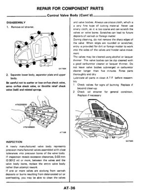
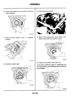
DISASSEMBLY
1. Remove torque converter, drain A.T.F
through end of
rear extension, and place trans-
mission on
Tool.
v
SAT520
2 Remove lock-up solenoid (E4N71B).
3. Remove converter housing.
SATOW
4. Remove oil pan and inspect its contents. An
analysis of any foreign matter can indicate the
types of problems to look for. If the fluid
IS
very dark, smells burned, or contains foreign
particles, the frictional material (clutches,
band.) may need replacement. A tacky film
that will not wipe clean indicates varnish bulld
up which can cause valves, servo, and clutches
to stick and may inhibit pump pressure.
SAT006
5. Loosen 2nd band servo piston stem lock nut
and tighten piston stem.
If it turns more than
two turns, the band
is worn out.
SAT71 5
AT-22
Page 23 of 99
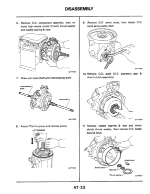
DISASSEMBLY
6. Remove O.D. component assembly, then re-
move high-reverse clutch (Front) thrust washer
and needle bearing
& race
7. Draw out input shaft and intermedtate shaft
8. Attach Tool to pump and remove pump.
SAT524
9. Remove 0.D servo cover, then loosen O.D.
band servo piston stem
SAT525
10. Remove O.D. pack (0 D planetary gear &
direct clutch assembly)
SAT526
11 Remove needle bearing & race and direct
clutch thrust washer, then remove
0 D. brake
band
& strut.
SAT527
AT-23
Page 24 of 99
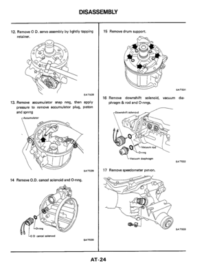
DISASSEMBLY
12. Remove 0 D. servo assembly by llghtly tapping
retainer.
n
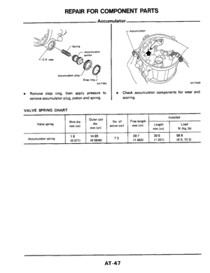
SAT528
13. Remove accumulator snap ring, then apply
pressure to remove accumulator plug, piston
and spring
rAccumUiatOr
14 Remove O.D. cancel solenoid and O-ring.
SAT530
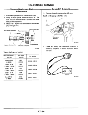
16 Remove downshift solenoid, vacuum dia-
phragm & rod and O-rings.
LVacuum diaphragm SAT532
17 Remove speedometer pinion.
SAT533
AT-24

 (Contd)
Inspecti")

Check inhibitor switch for operation
Check fluid level
in transmission.
Move selector lever through
all positions to be
sure that transmi")

@ 39 49140-50.29-361
@ 10- 15110- 15.7-11) @ 44.54 14 5 - 5 5,33 -401
@ 13 18113-1.8.9-13)
011 pump assembly & 5 -7 (05 -07.36.5 1) @ 8- 11 (08- 1.1,58-80)")

.
3. Remove converter h")
 thrust washer
and needle bearing
& race
7. Draw out input shaft and intermedtate shaft
8. Attach T")
