Page 57 of 99
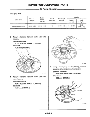
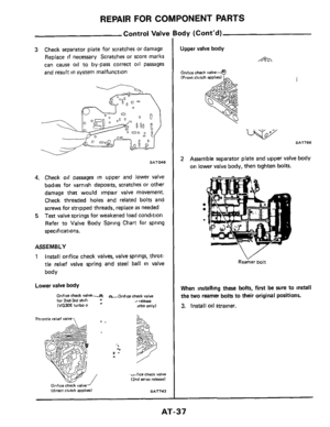
ASSEMBLY
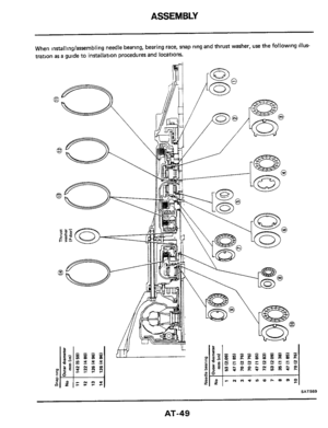
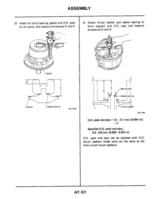
2) Install oil pump bearing, gasket and 0.D pack
on
oil pump, and measure dimensions F and H
w LGarker LNeedle bearing SAT735
3) Attach thrust washer and needle bearing to
drum support and O.D. case, and measure
dimensions
E and G
I1 Bearing race
Needle bearing
SAT736
D.D. pack end play = [E - 0.1 mm (0.004 in)]
-F
Specified O.D. pack end play:
0.5 - 0.8 mm (0.020 - 0.031 in)
0 D pack end play can be adjusted with O.D.
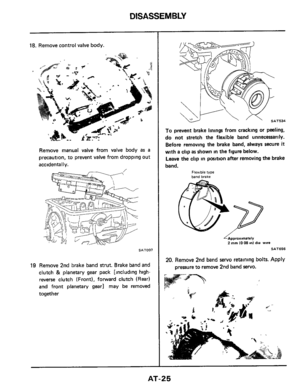
thrust washers (these parts are the same as the
front clutch thrust washers).
AT-57
Page 58 of 99
ASSEMBLY
15 (0 059)
17 (0 067)
19 (0 075)
2 1 (0 083)
2.3 (0 091)
25 (0098)
2 7 (0 106)
Available 0 D thrust washer
3 1528-XO106
31 528-XO105
31528-X0100
31 528-X0101
31 528-XO102
31528-XO103
31 528-XO104
Thickness mm (in) I Part number
Thickness mm (in) Part number
1 2 (0.047)
14 (0 055)
16 (0063)
18
(0071)
20 (0079)
22 (0087)
31556-X0100
3 1556-X0101
31556-X0102
31 556-XO103
31 556.X0104
31 556-XOlO5
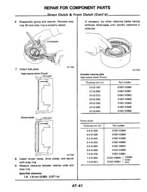
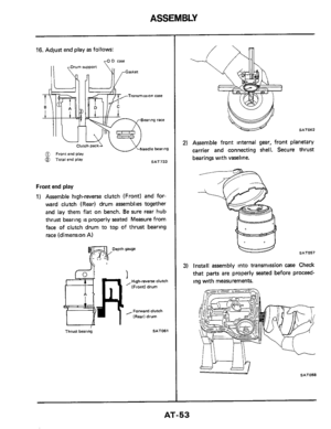
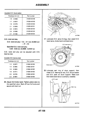
26. Adjust 2nd brake band. Tighten piston stem to
the specified value Back off two full turns and
secure with lock nut
SAT580
27. Lubricate O.D. servo O-rings, then install 0 D
band servo, brake band and band strut
7 0 D band %NO
SAT581
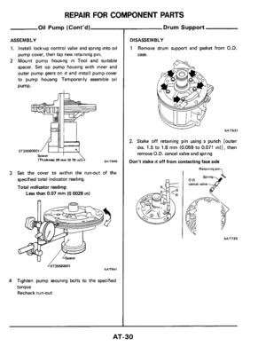
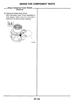
28. Lubricate seal ring of drum support, then
install
0 D. bearing & race, O.D. thrust washer
and
O.D. pack on drum support. Make sure
that brake band strut
is correctly installed.
70 D pack
AT-58
Page 59 of 99
ASSEMBLY
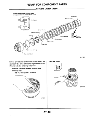
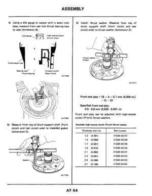
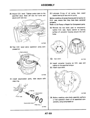
29. Adjust O.D. band Tighten piston stem to the
specified value Back off
two full turns and
secure with lock nut.
SAT625
30. Test 0.D band servo operation using corn-
pressed air.
apply pressure
SAT648
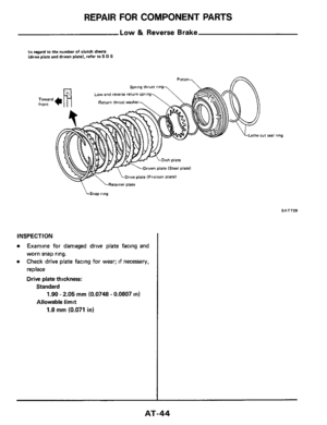
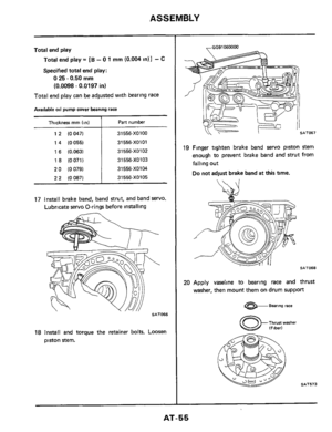
31. Install accumulator parts, then secure with
snap ring.
ACCUmUlafOr
Accumulator plug
Snap rmgi
SAT561
32. Lubricate O-ring of oil pump, then install
Before installing oil pump housing and oil pump on
O.D. case, ensure that they have been centered
properly.
Refer to Oil Pump in Repair for Component parts.
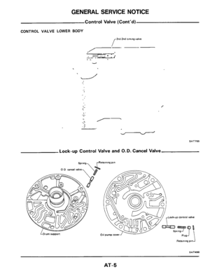
33. Remove the two bolts used to temporarily
tighten
O.D. case. Apply sealant to seating
surface
of converter housing around the bolt
holes
needle bearing & race and oil pump
APPIV sealant SAT738
34 Install converter housing on O.D. case and
35. Install input shaft.
tighten to the specified torque
.. SAT585
36. Before installlng valve body assembly perform
a final operation check of all assembled com-
ponents, using compressed air
AT-59
Page 60 of 99
ASSEMBLY
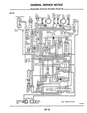
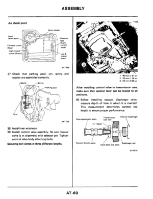
Air check point
Governor feed (From
valve) Forward clutch Control
LOW & reverse
brake
SAT586
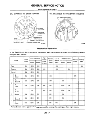
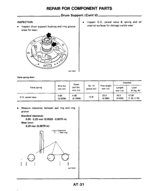
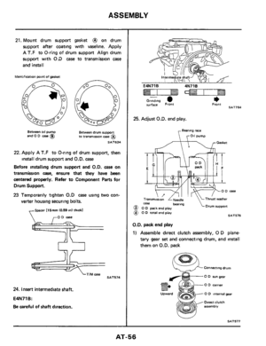
37 Check that parking pawl, pin, spring and
washer are assembled correctly.
rWasher
SAT739
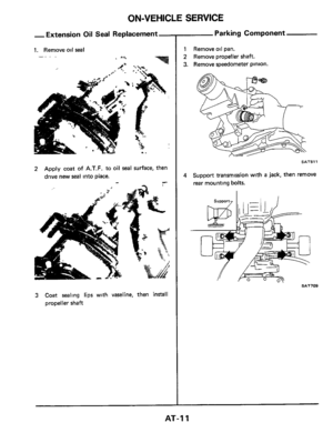
38. Install rear extension
39. Install control valve assembly. Be sure manual
valve
is in alignment with selector pin Tighten
control valve
body attaching bolts.
Securing bolt comes in three different lengths.
1 40 mm I1 57 ml
2 35 mm I1 38 m) 3 25 mm IO 98 1n1
After installing control valve to transmission case,
make sure that control lever can be moved to all
positions.
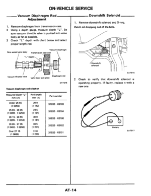
40 Before installing vacuum diaphragm valve,
measure depth of hole in which
it is inserted
This measurement determines correct rod
length to ensure proper performance.
"L ' Depth
Vacuum Diaphragm rod , throttle;alve / Valve body ride plate
AT-60
Page 61 of 99
ASSEMBLY
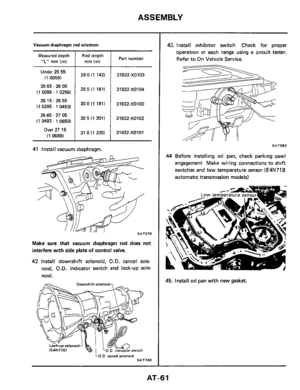
290 (1 142)
29 5 (1 161)
30 0 (1 1811
30 5 (1 201)
31 0 (1 220)
Vacuum diaphragm rod selection
31932-XO103
31932-X0104
31932-XOlOO
31932-X0102
31932-XOlOl
Measured depth
“L” mm (in)
Under 25 55
(1 0059)
25 65
- 26 05
(1
0098 - 1 02561
2615-2655
(1 0295 - 1 04531
26 65.27 05
(1 0492
- 1 0650)
Over 27 15
(1 0689)
Rod length
mm (in) Part number
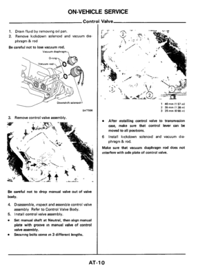
41 Install vacuum diaphragm.
Make sure that vacuum diaphragm rod does not
interfere with side plate
of control valve.
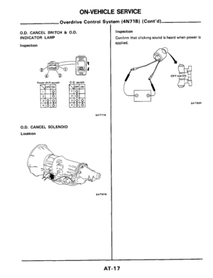
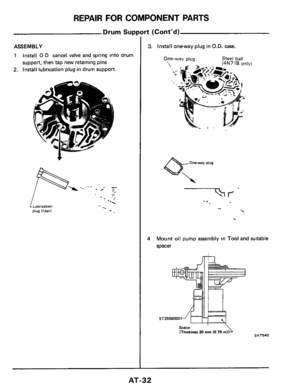
42 Install downshift solenoid, O.D. cancel sole-
noid, O.D. indicator switch and lock-up sole-
noid.
LO D csncei rolenoid SAT740
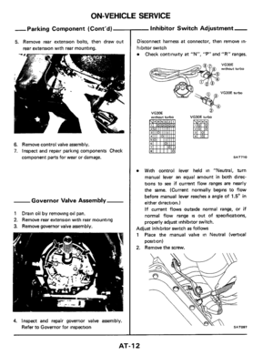
43. Install inhibitor switch Check for proper
operation in each range using
a circuit tester.
Refer to On Vehicle Service.
Y li
SAT082
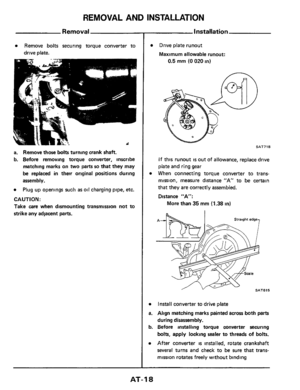
44 Before installing oil pan, check parking pawl
engagement Make wiring connections to shift
switches and low temperature sensor
(E4N71B
automatic transmission models)
45. Install oil pan with new gasket.
-
AT-61
Page 62 of 99
ASSEMBLY
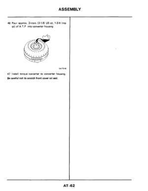
46 Pour approx. 2-liters (2-1/8 US qt, 1-3/4 Imp
qt) of A T.F into converter housing
SAT518
47 Install torque converter to converter housing.
Be careful not to scratch front cover oil seal.
AT-62
Page 63 of 99

FLUID LEAKAGE
To detect a fluid leak
1) Raise vehicle
2) Clean area suspected of leaking
3) Start engine, appl")
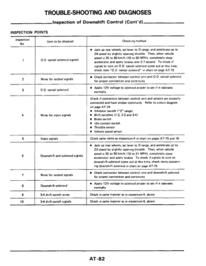
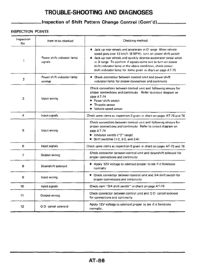
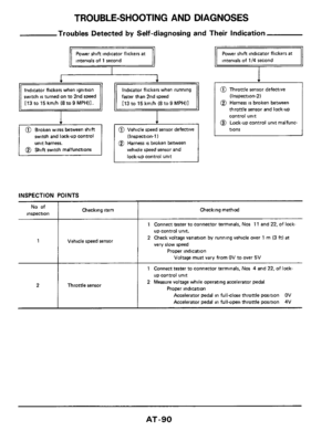
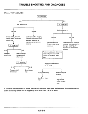
TROUBLE-SHOOTING AND DIAGNOSES
Preliminary Checks
(Prior to Road Testing)
FLUID LEAKAGE
To detect a fluid leak
1) Raise vehicle
2) Clean area suspected of leaking
3) Start engine, apply foot brake, place control
lever in drive, and wait a few minutes
4) Stop engine
5) Check for fresh leakage
FLUID CONDITION
Examine the AT F and note its color, texture,
and odor
1) Dark of Black Fluid
With a burned odor
- Worn friction material
2) Milky Pink Fluid Water Contamination
- Road water entering through filler
tube or breather
3) Varnished Fluid, light to dark brown and
tacky Oxidation
- Over or Underfilling
- Overheating
- Road Testing
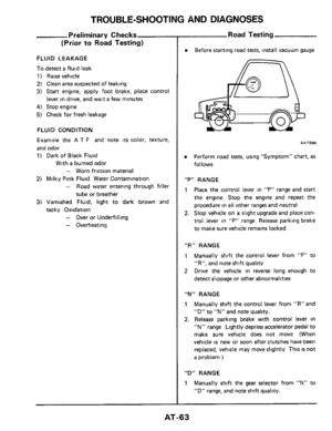
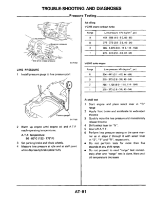
Before starting road tests, install vacuum gauge
SAT596
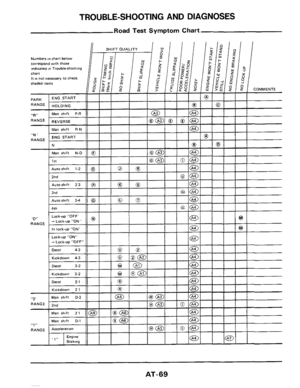
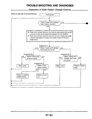
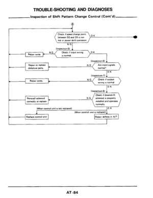
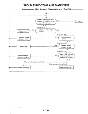
Perform road tests, using "Symptom" chart, as
follows
"P" RANGE
1 Place the control lever in "P" range and start
the engine Stop the engine and repeat the
procedure in all other ranges and neutral
2. Stop vehicle on a slight upgrade and place con-
trol lever
in "P" range Release parking brake
to make sure vehicle remains locked
"R" RANGE
1 Manually shift the control lever from "P" to
"R", and note shift quality
2 Drive the vehicle in reverse long enough to
detect slippage or other abnormalities
"M" RANGE
1 Manually shift the control lever from "R" and
"D"
to "N" and note quality.
2. Release parking brake with control lever in
"N" range Lightly depress accelerator pedal to
make sure vehicle does not move (When
vehicle
is new or soon after clutches have been
replaced, vehicle may move slightly This
IS not
a problem )
"D" RANGE
1 Manually shift the gear selector from "N" to
"D" range, and note shift quality.
-
AT-63
Page 64 of 99

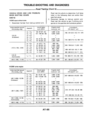
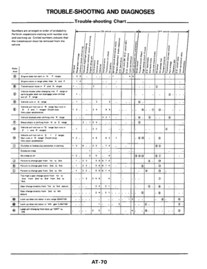
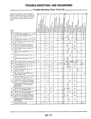
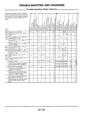
TROUBLE-SHOOTING AND DIAGNOSES
Road Test
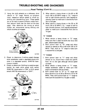
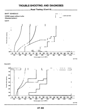
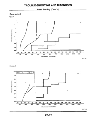
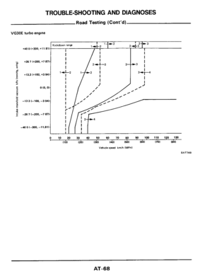
2 Using the shift schedule as a reference, drive
vehicle in
"D" range Record, on symptom
chart, respective vehicle speeds
at which up-
shifting and downshifting occur These speeds
are to be read at several different intake mani-
fold vacuum levels
(see the chart on the next
page). Also determine the timing
at which
shocks are encountered during shifting and
which clutches
are engaged
Drive on different throttle condirtom
SAT590
3. Check to determine if shifting speed changes
when accelerator pedal
is depressed slowly and
when
it is depressed quickly (E4N71B trans-
mission models)
4 Check to determine if shifting to overdrive gear
cannot be made while power shift switch
(E4N71B transmission) is"0N" or
O.D. cancel
switch (4N71
B transmission) is "OFF".
0 0. cancel witch SAT744
3 (Cont'd)
5. When vehicle is being driven in the 65 to 85
km/h (40 to 53 MPH) range in "Ds" range at
half to light throttle position, fully depress ac-
celerator pedal to make sure
it downshifts from
3rd to 2nd
gear.
6. When vehicle is being driven in the 25 to 35
km/h (16 to 22 MPH) ("D," range) at half to
light throttle position, fully depress accelerator
pedal to make sure
it downshifts from 2nd to
1 st gear
"2" RANGE
1 While vehicle is being driven in "2" range,
make sure that
it does not shift into 1st or 3rd
gear, despite speed changes.
2 Shift control lever to "D" range and allow
vehicle to operate
at 40 to 50 km/h (25 to 31
MPH) Then, shift to "2" range to make sure
it downshifts to 2nd gear.
"1" RANGE
1. Shift control lever to "1" range and allow
vehicle to run. Ensure
that it does not upshift
from 1st to 2nd gear although vehicle speed
increases
2 While vehicle is being driven in "1" range,
release accelerator pedal
to make sure that
engine compression acts
as a brake
3. Shift control lever to "D" or "2" range and
allow vehicle to run
at 20 to 30 km/h (12 to 19
MPH). Then, shift control lever to "1" range to
make sure the downshift to 1st gear is made.
AT-64

 Install oil pump bearing, gasket and 0.D pack
on
oil pump, and measure dimensions F and H
w LGarker LNeedle bearing SAT735
3) Attach thrust washer and needle bearing to
dru")

17 (0 067)
19 (0 075)
2 1 (0 083)
2.3 (0 091)
25 (0098)
2 7 (0 106)
Available 0 D thrust washer
3 1528-XO106
31 528-XO105
31528-X0100
31 528-X0101
31 528-XO102
3152")

 Forward clutch Control
LOW & reverse
brake
SAT586
37 Check that parking pawl, pin, spring and
washer are assembled correctly.
rWasher")

29 5 (1 161)
30 0 (1 1811
30 5 (1 201)
31 0 (1 220)
Vacuum diaphragm rod selection
31932-XO103
31932-X0104
31932-XOlOO
31932-X0102
31932-XOlOl
Measured depth
“L�")
 of A T.F into converter housing
SAT518
47 Install torque converter to converter housing.
Be careful not to scratch front cover oil")