Page 25 of 99
DISASSEMBLY
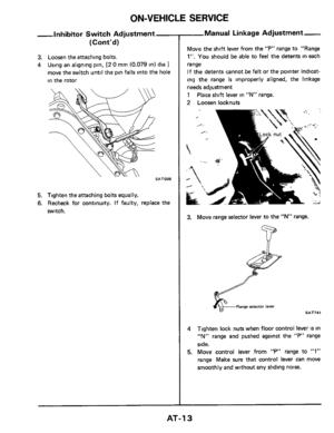
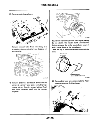
18. Remove control valve body.
Remove manual valve from valve body as a
precaution, to prevent valve from dropping out
accidentally.
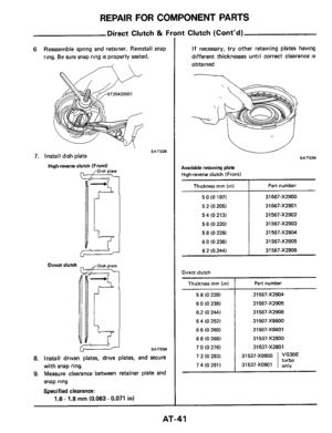
SAT007
19 Remove 2nd brake band strut. Brake band and
clutch
& planetary gear pack [Including high-
reverse clutch (Front), forward clutch (Rear)
and front
planetary gear] may be removed
together
To prevent brake linings from cracking or peeling,
do not stretch the flexible band unnecessarily.
Before removing the brake band, always secure
it
with a clip as shown in the figure below.
Leave the clip
in position after removing the brake
band.
Flexible type band brake
2 mm 1008 In) dia wire
SAT656
20. Remove 2nd band servo retalning bolts. Apply
pressure to remove 2nd band =NO.
AT-25
Page 26 of 99
6ut~ deus Veqs indino artowau '&z
SLOlVS
Page 27 of 99
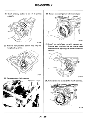
DISASSEMBLY
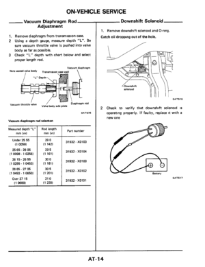
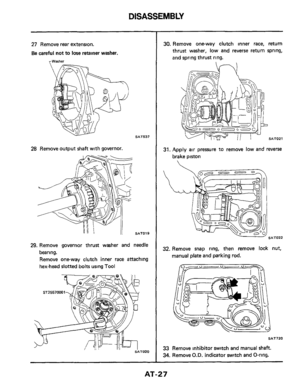
27 Remove rear extension.
Be careful not to lose retainer washer.
rWarher
SAT537
2% Remove output shaft with governor.
11 SAT019
29. Remove governor thrust washer and needle
bearing.
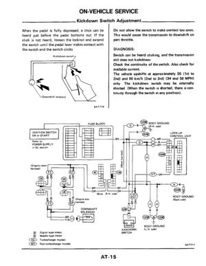
Remove one-way clutch inner race attaching
hex-head slotted bolts using
Tool
30. Remove one-way clutch inner race, return
thrust washer, low and reverse return spring,
and spring thrust ring.
31. ,Apply air pressure to remove low and reverse
brake piston
. ' SAT022
32. Remove snap ring, then remove lock nut,
manual plate and parking rod.
y- - " -
SAT720
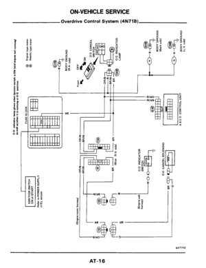
33 Remove Inhibitor switch and manual shah.
34. Remove
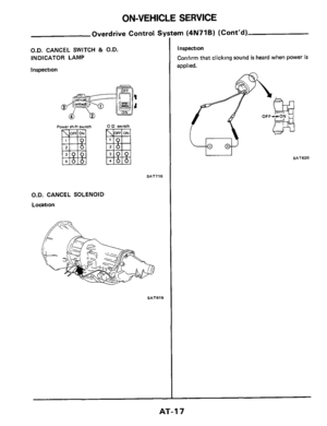
O.D. indicator switch and O-ring.
AT-27
Page 28 of 99
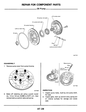
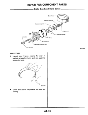
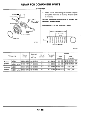
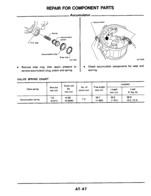
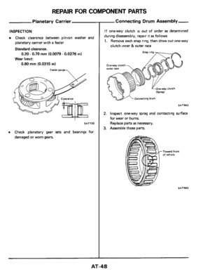
REPAIR FOR COMPONENT PARTS
Oil Pump
011 pump inner gear,
pump =Over
1
011 pump housing
Lathe cur seal
011 seal
l
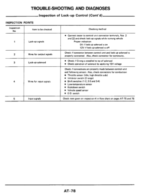
Lock-up control valve
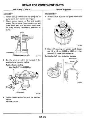
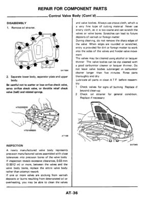
DISASSEMBLY
1 Remove pump cover from pump housing
2. Stake off retaining pin using a punch [outer
dia.
1.5 to 1.8 mm (0.059 to 0.071 in)], then
remove lock-up control valve and spring
B
SAT721
SAT722
INSPECTION
1. Inspect pump body, bushing and pump shaft,
for
wear.
2. Inspect gears, lock up control valve, spring and
all internal surfaces for damage and visible
wear.
AT-28
Page 29 of 99
REPAIR FOR COMPONENT PARTS
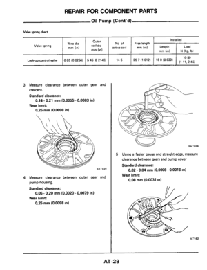
No of
active coil
Outer
coil dia
rnrn (in)
Wire dia
rnrn (in) Valve spring
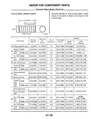
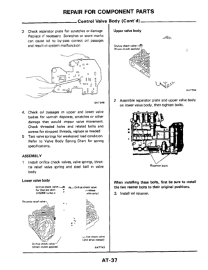
Oil Pump (Cont’d)
Valve spring chart
Installed
Length
rnrn (in) N (kg. Ib)
Free length
rnrn (in)
Lock-up control valve 10 89 0 65 (0 02561 5 45 (0 21461 14 5 25 7 (1 0121 16 0 (0 630) (1 11, 45)
3 Measure clearance between outer gear and
crescent.
Standard clearance:
Wear limit:
0.14 - 0.21 mm (0.0055 - 0.0083 in)
0.25
mm (0.0098 in)
4 Measure clearance between outer gear and
pump housing.
Standard clearance:
Wear limit:
0.05 - 0.20 mm (0.0020 - 0.0079 in)
0.25
mm (0.0098 in)
5
SAT026
Using a feeler gauge and straight edge, measure
clearance between
gears and pump cover
Standard clearance:
0.02
- 0.04 mm (0.0008 - 0.0016 in)
Wear limit:
0.08 mm (0.0031 in)
AT162
AT-29
Page 30 of 99
REPAIR FOR COMPONENT PARTS
Oil Pump (Cont'd)
ASSEMBLY
1. Install lock-up control valve and spring into oil
pump cover, then tap new retaining pin.
2 Mount pump housing in Tool and suitable
spacer. Set up pump housing with inner and
outer pump gears on
it and install pump cover
to pump housing Temporarily assemble
oil
pump.
sar-0
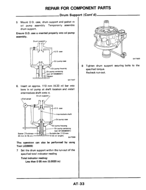
3 Set the cover to within the run-out of the
specified total indicator reading.
Total indicator reading:
Less than 0.07 mm (0 0028 in)
SAT541 &25580001
4 Tighten pump securing bolts to the specified
torque Recheck run-out
Drum Support
DISASSEMBLY
1 Remove drum support and gasket from O.D.
case.
SATW
2. Stake off retaining pin using a punch [outer
dia.
1.5 to 1.8 mm (0.059 to 0.071 in)], then
remove
O.D. cancel valve and spring
Don't stake it off from contacting face side
7 Retaining pin
00
AT-30
Page 31 of 99
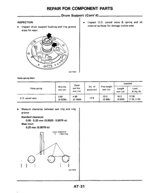
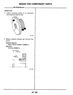
INSPECTION
a Inspect drum support bushing and ring groove
areas for wear.
SAT542 I
a Inspect O.D. cancel valve & spring and all
internal surfaces for damage visible wear
No of Freelength Outer
Valve spring
coil dia active coil mm (in) mm (In) mm (in)
Wire dia
0 65 4 95 23 0
(0 0256) (0 1949) (0 9061 12 8 0 D. canel valve
Measure clearance between seal ring and ring
groove
Standard clearance:
Wear limit:
0.05 - 0.20 rnrn (0.0020 - 0.0079 in)
0.20 mm (0.0079 in)
Installed
Length Load
mm (in) N (kg, Ib)
16 0 12 26
(0 630) (1 25, 2 76)
IIII I I II
SAT545
AT-31
Page 32 of 99
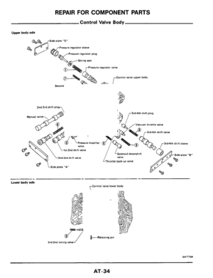
REPAIR FOR COMPONENT PARTS
Drum Support (Cont'd)
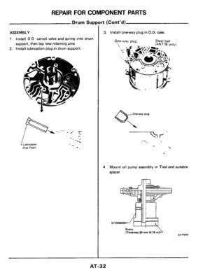
ASSEMBLY
1 Install 0 D cancel valve and spring into drum
suppon, then tap new retaining pins
2. Install lubrication plug in drum support
! Lubrication plug Iflbed
3. Install oneway plug in O.D. case.
One-way plug Steel ball
':
Oneway plug
4M int oil pum
spacer
assembly in Tool and suitable
[Thickness 20 mm IO 79 In SAT540
AT-32


Wire dia
rnrn (in) Valve spring
Oil Pump (Cont’d)
Valve spring chart
Installed
Length
rnrn (in) N (kg. Ib)
Free")

ASSEMBLY
1. Install lock-up control valve and spring into oil
pump cover, then tap new retaining pin.
2 Mount pump housing in Tool and suitabl")


ASSEMBLY
1 Install 0 D cancel valve and spring into drum
suppon, then tap new retaining pins
2. Install lubrication plug in drum support
!")