1984 NISSAN 300ZX sensor
[x] Cancel search: sensorPage 2 of 99
DESCRIPTION OF E4N71B
I
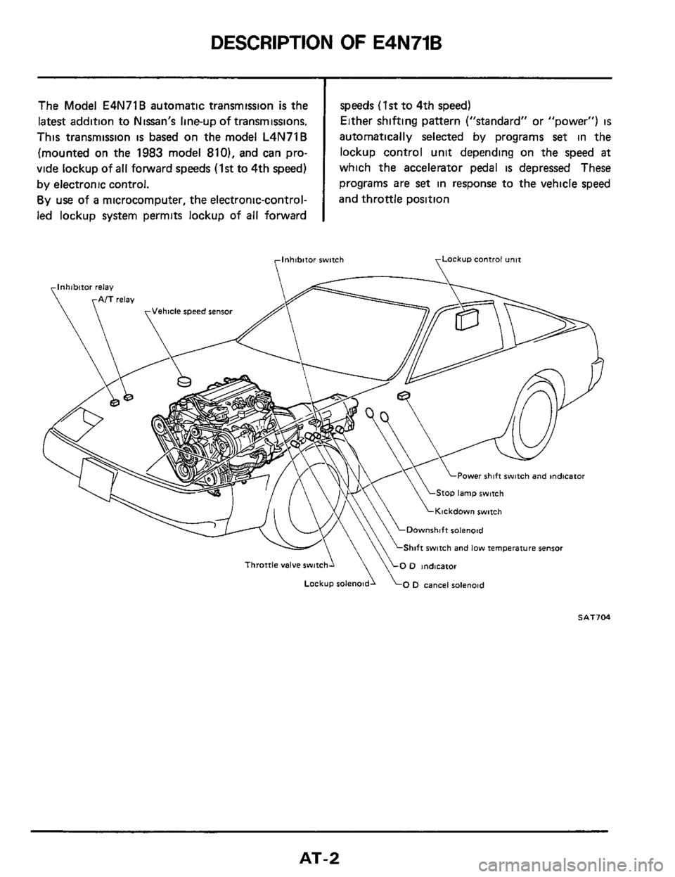
The Model E4N71B automatic transmission is the
latest addition to Niaan's lineup
of transmissions.
This transmission
is based on the model L4N71B
(mounted on the 1983 model 810), and can pro-
vide lockup of
all forward speeds (1st to 4th speed)
by electronic control.
By use of a microcomputer, the electronic-control-
led lockup system permits lockup of
all forward
speeds (1st to 4th speed)
Either shifting pattern ("standard" or "power")
is
automatically selected by programs set in the
lockup control unit depending on the speed
at
which the accelerator pedal is depressed These
programs are
set in response to the vehicle speed
and throttle position
rlnhibitor switch \Lockup control unit
/;?\I!
LPower Shift switch and mdtcator
Stop lamp rwlrch
\Kickdown switch
Downshift solenoid
Shift switch and low temperature sensor
Throttle valve rwitchl 0 indicator
Lockup solenoid 0 D cancel solenoid
SAT7M
AT-2
Page 61 of 99
ASSEMBLY
290 (1 142)
29 5 (1 161)
30 0 (1 1811
30 5 (1 201)
31 0 (1 220)
Vacuum diaphragm rod selection
31932-XO103
31932-X0104
31932-XOlOO
31932-X0102
31932-XOlOl
Measured depth
“L” mm (in)
Under 25 55
(1 0059)
25 65
- 26 05
(1
0098 - 1 02561
2615-2655
(1 0295 - 1 04531
26 65.27 05
(1 0492
- 1 0650)
Over 27 15
(1 0689)
Rod length
mm (in) Part number
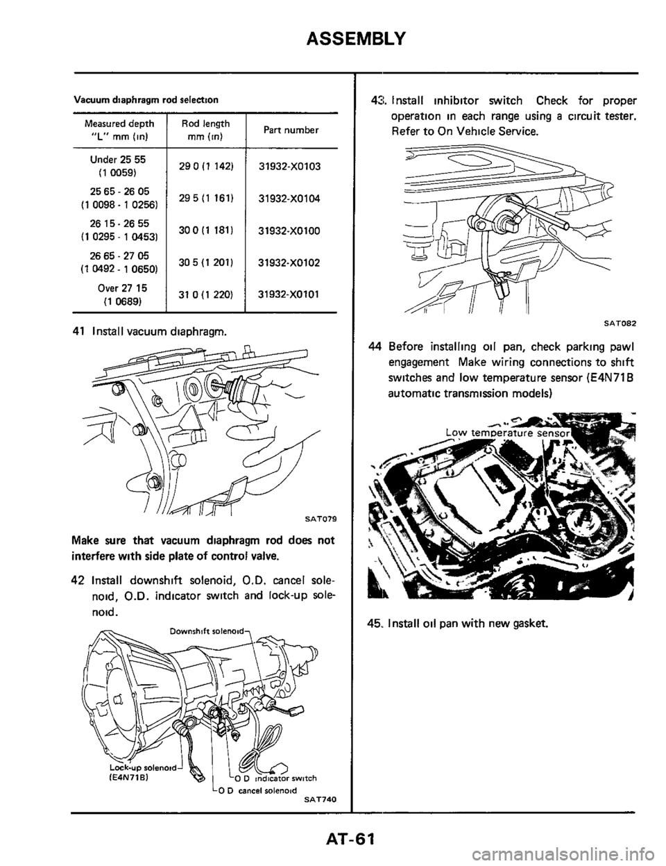
41 Install vacuum diaphragm.
Make sure that vacuum diaphragm rod does not
interfere with side plate
of control valve.
42 Install downshift solenoid, O.D. cancel sole-
noid, O.D. indicator switch and lock-up sole-
noid.
LO D csncei rolenoid SAT740
43. Install inhibitor switch Check for proper
operation in each range using
a circuit tester.
Refer to On Vehicle Service.
Y li
SAT082
44 Before installing oil pan, check parking pawl
engagement Make wiring connections to shift
switches and low temperature sensor
(E4N71B
automatic transmission models)
45. Install oil pan with new gasket.
-
AT-61
Page 75 of 99
TROUBLE-SHOOTING AND DIAGNOSES
inspection of Lock-up Control Unit
Terminal
No Checking inputloutput signal
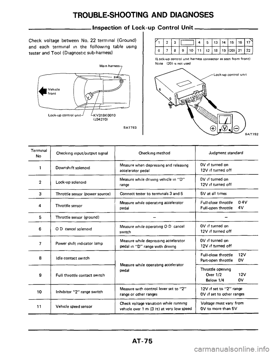
Check voltage between No. 22 terminal (Ground)
and each terminal in the following table using
tester and Tool (Diagnostic
sub-harness)
Judgment standard Checking method
7 Main harness
I 5 1 Throttle sensor (ground) -
Lock-up control und LKV319K0010 lJ34270)
SAT163
- I
(Lock-up control unif harness ~onnecfor as seen from front)
Nate 1201 IS not used ~~
11
Lock-up control unit
7
Check
voltage variation while running
vehicle over
1 rn (3 tt) at very low speed
Voltage must vary from
OV to more than 5V Vehicle speed sensor
1 I Downshift solenoid Measure when depressing and releasing
accelerator pedal OV if turned on
12V if turned off
2 1 Lock-upsolenoid Measure while driving vehicle in "0"
I range
OV if turned on
12V
if turned off
3 I Throttle sensor (power source) I Connect tester to terminals 3 and 5 I 5V at all times
4 I Throttlesensor Measure while operating accelerator
I pedal
Full-close throttle 04V
Full-open throttle 4V
6 1 0 D cancel solenoid Measure while operating 0 D cancel
switch OV if turned on
12V if turned
off
Measure while depressing accelerator
pedal in
"Dr range with driving Power shift indicator lamp 7
Idle contact switch
Measure while operating accelerator
pedal
Full throttle contact switch
Measure with control lever set to "2"
range or other ranges 10 1 Inhibitor "2" range switch
OV if turned on
12V if turned
off
Full-close throttle 12V
Part-open throttle OV ~~
~~
Throttle opening
Over 1 I2 12v
Below
114 ov
12V if set to "2" range
OV
if set to other ranges
AT-75
Page 76 of 99
TROUBLE-SHOOTING AND DIAGNOSES
Inspection of Lock-up Control Unit (Cont'd)
Terminal
No
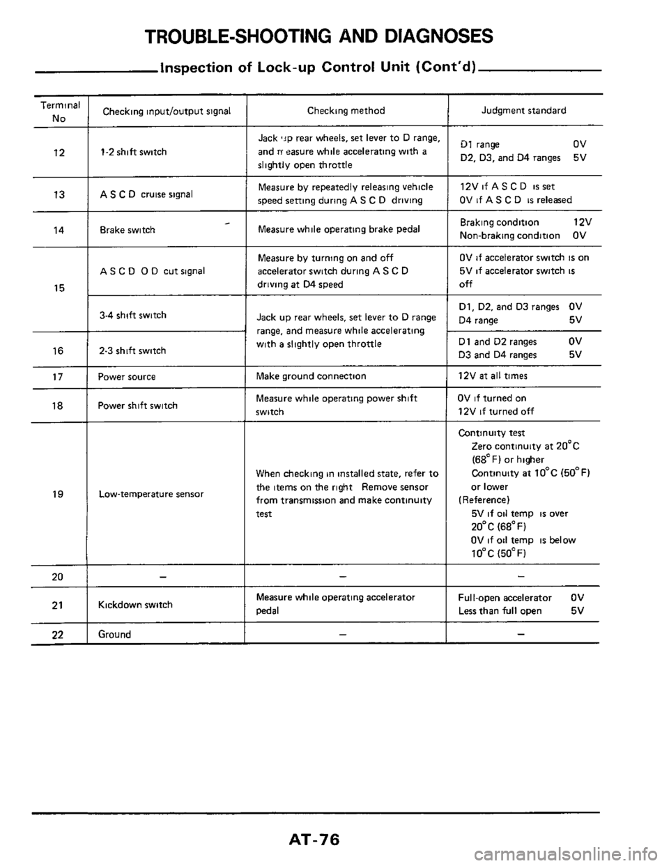
12
13
14
15
16
17
18
19
20
21
22
___
Checking inputloutput signal
1-2 shift switch
AS C D cruise signal
- Brake switch
A S C 0 0 D cut signal
3-4 shift switch
2-3 shift switch
Power source
Power shift switch
Low-temperature sensor
Kickdown switch
Ground
Checking method
Jack 'JP rear wheels, set lever to D range,
and
ri easure while accelerating with a
slightly open throttle
Measure by repeatedly releasing vehicle
speed setting during
AS C D driving
Measure while operating brake pedal
Measure by turning on and off
accelerator switch during A S C D
driving at D4 speed
Jack up rear wheels, set lever to D range
range,
and measure while accelerating
with
a slightly open throttle
Make ground connection
Measure while operating power shift
switch
When checking in installed state, refer to
the items on the right Remove sensor
from transmission and make continuity
test
Measure while operating acceleratoi
pedal
Judgment standard
D1 range ov
D2. D3, and 04 ranges
12VifASCD
isset
OV if AS C D is released
5V
Braking condition 12v
Non-braking condition OV
OV if accelerator switch is on
5V
if accelerator switch is
off
D1, D2. and D3 ranges OV
D4 range 5v
D1 and D2 ranges
ov
D3 and D4 ranges 5v
12V
at all times
OV if turned on
12V
if turned off
Continuity test
Zero continuity at 20'c
(68OF) or higher
Continuity
at 10°C (50°F)
or lower
(Reference)
5V
if oil temp is over
20°C (68°F)
OV if oil temp
is below
10°C (5OOF)
Ful I-open accelerator OV
Less than
full open 5v
AT-76
Page 78 of 99
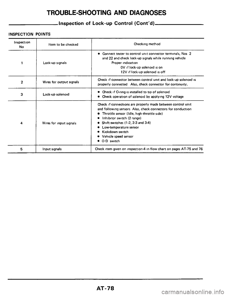
TROUBLE-SHOOTING AND DIAGNOSES
inspection of Lock-up Control (Cont'd)
INSPECTION POINTS
Inspection
No
1
2
3
4
5
Item to be checked
Lock-up signals
Wires for output signals
Lock-up solenoid
Wires for input signals
hut sianals
Checking method
e Connect tester to control unit connector terminals, Nos 2
and 22 and check lock-up signals while running vehicle
Proper indication
OV if lock-up solenoid is on
12V if lockup solenoid
is off
Check if connector between control unit and lock-up solenoid is
properly connected Also. check connector for continuity.
e Check if O-ring is installed to tip of solenoid
e Check operation of solenoid by applying 12V voltage
Check if connections are properly made between control unit
and following sensors Also. check connectors for conduction
Throttle sensor (Idle. high-throttle side)
e Inhibitor switch (2 range)
Shift switches (1-2.2-3 and 3-4)
Low-temperature sensor
e Kickdown switch
e Vehicle speed sensor
e 0 D switch
Check item given on inspection4 in flow chart on pages AT-75 and 76
AT-78
Page 79 of 99
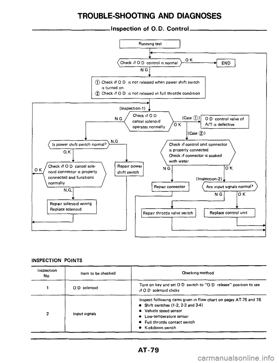
TROUBLE-SHOOTING AND DIAGNOSES
Inspection of O.D. Control
OK operates normally
Running test1
AIT is defective
(Case 0)
END OK
@ Check if 0 D is not released when power shift switch
@ Check if 0 D is not released in full throttle condition
is turned on
NG witch OK
N.G +
( Is power shift switch normal,) I ,
0. K
Check if 0 D cancel sole-
noid connector
is properly
connected and functions
normally
Replace solenoid
I
/Check if control unit connector
IS properly connected
Check
if connector is soaked
with water
I (Inspection-2)
NG OK
INSPECTION POINTS
Qlecking method Inspection
No Item to be checked
'I 0 D solenoid Turn on key and set 0 D switch to "0 D release" position to see
if 0 D solenoid clicks I I
Inspect following items given in flow chart on pages AT-75 and 76
Shift switches (1-2, 2-3 and 34)
Input signals 21
0 Vehicle speed sensor
0 Lowtemperature sensor
0 Full throttle contact switch
Kickdown switch
AT-79
Page 82 of 99
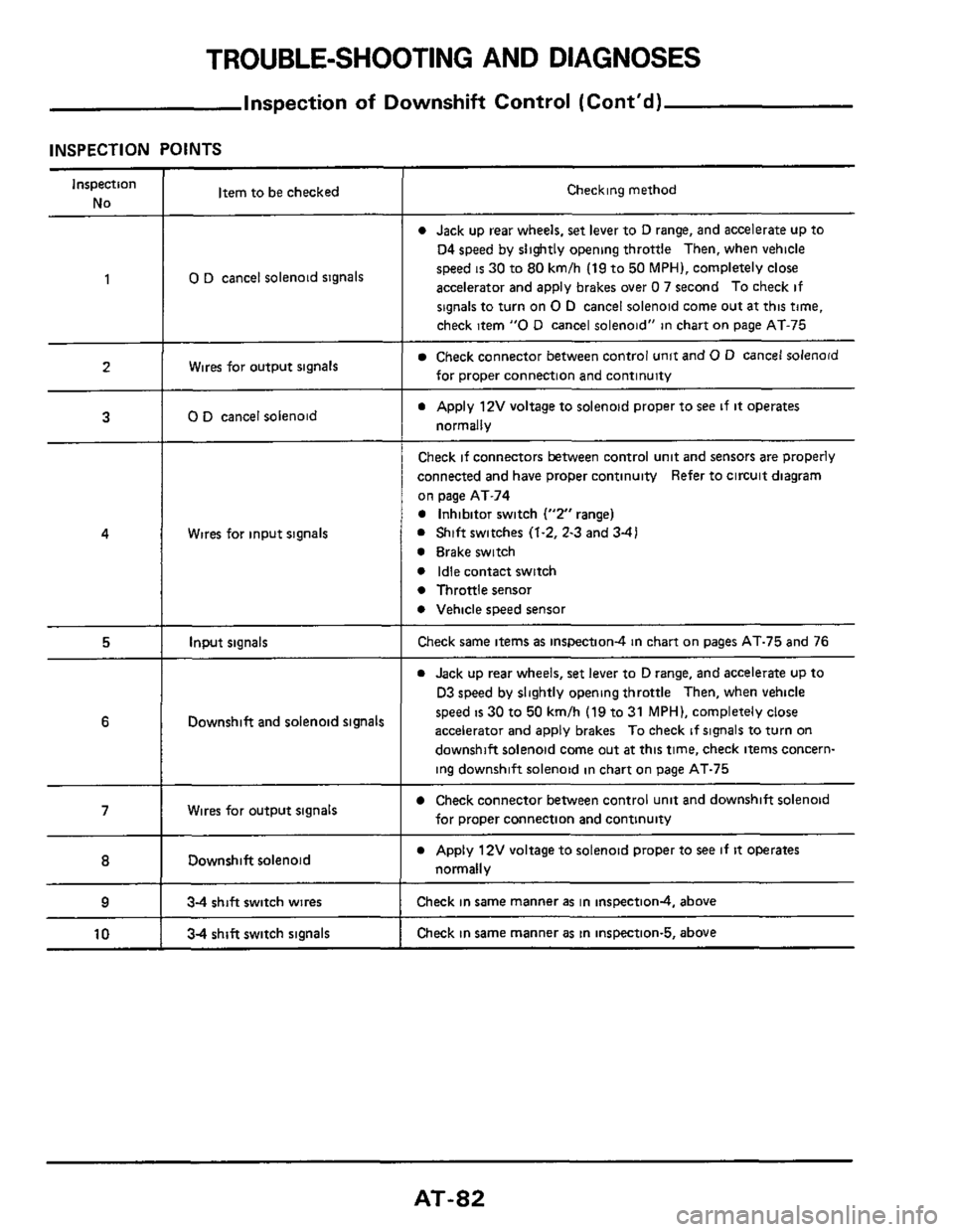
TROUBLE-SHOOTING AND DIAGNOSES
Inspection of Downshift Control (Cont'd)
INSPECTION POINTS
Inspection
No Item to be checked Checking method
0 Jack up rear wheels, set lever to D range, and accelerate up to
04 speed by slightly opening throttle Then, when vehicle
speed
is 30 to 80 kmlh (19 to 50 MPH), completely close
accelerator and apply brakes over
0 7 second To check if
signals to turn on
0 D cancel solenoid come out at this time,
check item
"0 D cancel solenoid" in chart on page AT-75
1 0 D cancel solenoid signals
Wires for output signals Check connector between control unit and 0 D cancel solenoid
for proper connection and continuity
a Apply 12V voltage to solenoid proper to see if it operates
normally
2
3 0 D cancel solenoid
Wires for input signals
Check if connectors between control unit and sensors are properly
connected and have proper continuity Refer to circuit diagram
on page AT-74
0 Inhibitor switch ("2" range)
0 Shift switches (1.2, 2-3 and 3-41
0 Brake switch
0 Idle contact switch
0 Throttle sensor
0 Vehicle speed sensor
4
5 Input signals Check same items as inspection4 in chart on pages AT-75 and 76
0 Jack up rear wheels, set lever to D range, and accelerate up to
D3 speed by slightly opening throttle Then, when vehicle
speed
is 30 to 50 kmlh (19 to 31 MPH), completely close
accelerator and apply brakes To check
if signals to turn on
downshift solenoid come out
at this time, check items concern-
ing downshift solenoid in chart on page AT-75
6 Downshift and solenoid signals
Check connector between control unit and downshift solenoid
for proper connection and continuity 7 Wires for output signals
Downshift solenoid
___ ~~ ~~~
0 Apply 12V voltage to solenoid proper to see if it operates
normally 8
9 34 shift switch wires Check in same manner as in inspectiond, above
Check in same manner
as in inspection-5, above 10 34 shift switch signals
AT-82
Page 86 of 99
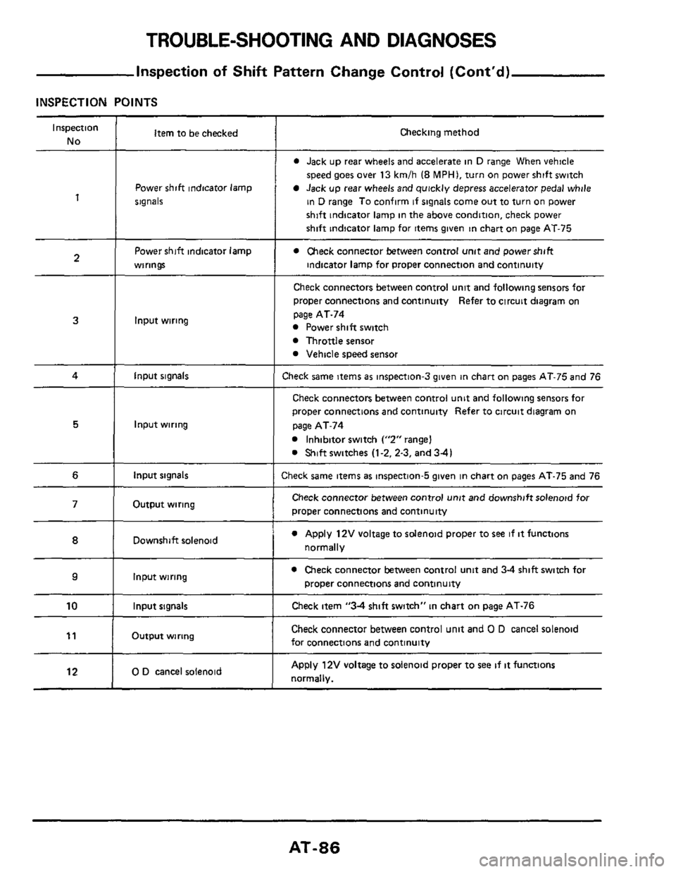
TROUBLE-SHOOTING AND DIAGNOSES
Inspection of Shift Pattern Change Control (Cont'd)
INSPECTION POINTS
Inspection
No
1
2
Item to be checked
Power shift indicator lamp
signals
Power shift indicator lamp
wirings
3
4 I input signals
Input wiring
5
6 I input signals
Input wiring
Output wiring 71
12
Downshift solenoid
Input wiring ~~
0 D cancel
solenoid
IO I Input signals
Output wiring l1 I
Checking method
0 Jack up rear wheels and accelerate in D range When vehicle
speed goes over 13 kmlh (8 MPHI, turn on power shift switch
Jack up rear wheels and quickly depress accelerator pedal while
in
D range To confirm if signals come out to turn on power
shift indicator lamp in the above condition, check power
shift indicator lamp for items given in chart
on page AT-75
0 Check connector between control unit and powershift
indicator lamp for proper connection and continuity
Check connectors between control unit and following sensors foi
proper connections and continuity Refer to circuit diagram on
page AT-74
Power shift switch
Throttle sensor
Vehicle speed sensor
:heck same items as inspection-3 given in chart on pages AT-75 and 76
Check connectors between control unit and following sensors for
proper wnnections and continuity Refer to circuit diagram on
page AT-74
Inhibitor switch Y2"rangeI
0 Shift switches (1-2.2-3, and 34)
:heck same items as inspection-5 given in chart on pages AT-75 and 76
Check connector between control unit and downshift solenoid for
proper connections and continuity
0 Apply 12V voltage to solenoid proper to see if it functions
normally
0 Check connector between control unit and 3-4 shift switch for
proper connections and continuity
Check item "34 shift switch" in chart on page AT-76
Check connector between control unit and 0 D cancel solenoid
for connections and continuity
Apply 12V voltage to solenoid proper to see if it functions
normally.
AT-86