1984 NISSAN 300ZX wheel
[x] Cancel search: wheelPage 7 of 99
GENERAL SERVICE NOTICE
I (Cont'd) Oil Cham
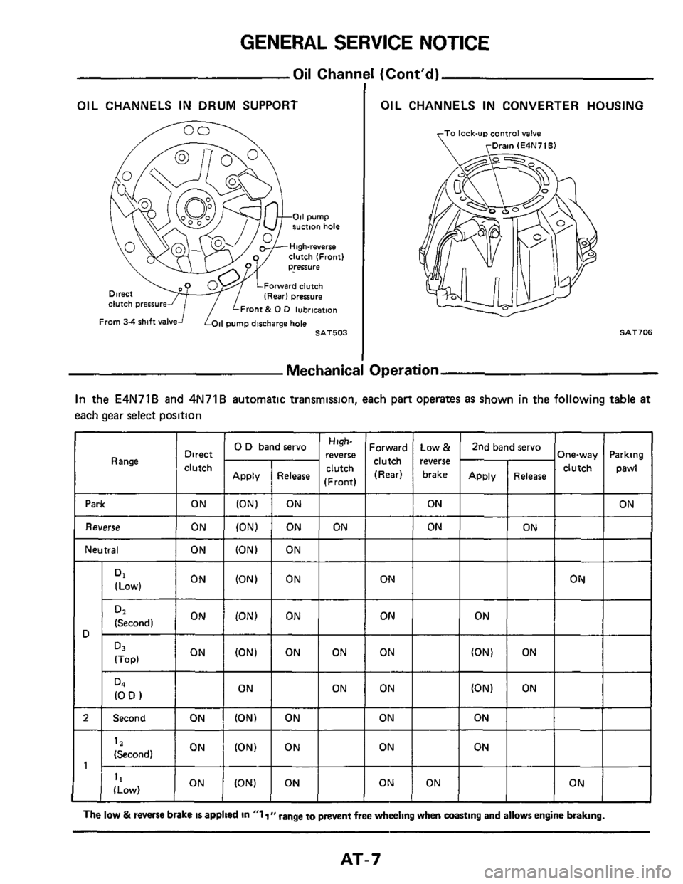
OIL CHANNELS IN DRUM SUPPORT OIL CHANNELS IN CONVERTER HOUSING
To lock-up ~ontrol valve
rDrain (E4N71Bl
clutch (Front)
Forward clutch
clutch pressure Front & 0 0 lubrmtmn
SAT706
3peration Mechanic:
In the E4N71B and 4N71B automatic transmission, each part operates as shown in the following table at
each gear select position
'arking
pawl
Htgh-
'everse
Front) Forward clutch (Rear) 0 D band servo Direct
clutch Range -
Release
ON ON
1 Reverse 1 ON 1 ION) ON
+-
ON I
I Neutral I ON I (ON) ON
T-
ON
-
ON
-
ON
ON
JT
I ION
'34
(0 D 1 ON I ON
Second I ON I (ON) ON
1 ON I (ON) 12
(Second) ON ON I ON
ON ord ON I I ON
The low & reverse brake IS applied In "1 I" range to prevent free wheeling when coasting and allows engine braking.
AT-7
Page 76 of 99
TROUBLE-SHOOTING AND DIAGNOSES
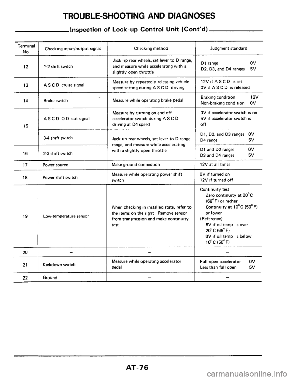
Inspection of Lock-up Control Unit (Cont'd)
Terminal
No
12
13
14
15
16
17
18
19
20
21
22
___
Checking inputloutput signal
1-2 shift switch
AS C D cruise signal
- Brake switch
A S C 0 0 D cut signal
3-4 shift switch
2-3 shift switch
Power source
Power shift switch
Low-temperature sensor
Kickdown switch
Ground
Checking method
Jack 'JP rear wheels, set lever to D range,
and
ri easure while accelerating with a
slightly open throttle
Measure by repeatedly releasing vehicle
speed setting during
AS C D driving
Measure while operating brake pedal
Measure by turning on and off
accelerator switch during A S C D
driving at D4 speed
Jack up rear wheels, set lever to D range
range,
and measure while accelerating
with
a slightly open throttle
Make ground connection
Measure while operating power shift
switch
When checking in installed state, refer to
the items on the right Remove sensor
from transmission and make continuity
test
Measure while operating acceleratoi
pedal
Judgment standard
D1 range ov
D2. D3, and 04 ranges
12VifASCD
isset
OV if AS C D is released
5V
Braking condition 12v
Non-braking condition OV
OV if accelerator switch is on
5V
if accelerator switch is
off
D1, D2. and D3 ranges OV
D4 range 5v
D1 and D2 ranges
ov
D3 and D4 ranges 5v
12V
at all times
OV if turned on
12V
if turned off
Continuity test
Zero continuity at 20'c
(68OF) or higher
Continuity
at 10°C (50°F)
or lower
(Reference)
5V
if oil temp is over
20°C (68°F)
OV if oil temp
is below
10°C (5OOF)
Ful I-open accelerator OV
Less than
full open 5v
AT-76
Page 82 of 99
TROUBLE-SHOOTING AND DIAGNOSES
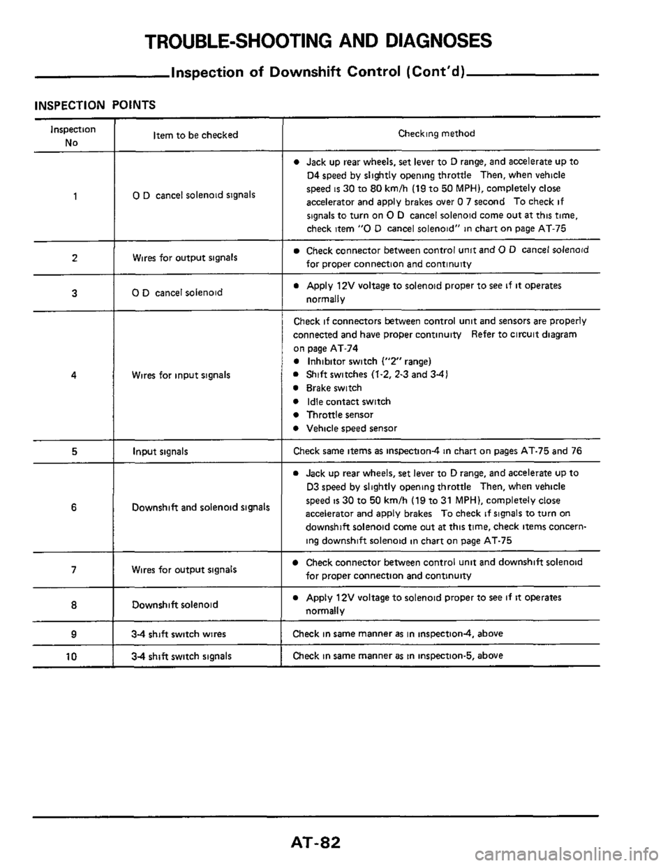
Inspection of Downshift Control (Cont'd)
INSPECTION POINTS
Inspection
No Item to be checked Checking method
0 Jack up rear wheels, set lever to D range, and accelerate up to
04 speed by slightly opening throttle Then, when vehicle
speed
is 30 to 80 kmlh (19 to 50 MPH), completely close
accelerator and apply brakes over
0 7 second To check if
signals to turn on
0 D cancel solenoid come out at this time,
check item
"0 D cancel solenoid" in chart on page AT-75
1 0 D cancel solenoid signals
Wires for output signals Check connector between control unit and 0 D cancel solenoid
for proper connection and continuity
a Apply 12V voltage to solenoid proper to see if it operates
normally
2
3 0 D cancel solenoid
Wires for input signals
Check if connectors between control unit and sensors are properly
connected and have proper continuity Refer to circuit diagram
on page AT-74
0 Inhibitor switch ("2" range)
0 Shift switches (1.2, 2-3 and 3-41
0 Brake switch
0 Idle contact switch
0 Throttle sensor
0 Vehicle speed sensor
4
5 Input signals Check same items as inspection4 in chart on pages AT-75 and 76
0 Jack up rear wheels, set lever to D range, and accelerate up to
D3 speed by slightly opening throttle Then, when vehicle
speed
is 30 to 50 kmlh (19 to 31 MPH), completely close
accelerator and apply brakes To check
if signals to turn on
downshift solenoid come out
at this time, check items concern-
ing downshift solenoid in chart on page AT-75
6 Downshift and solenoid signals
Check connector between control unit and downshift solenoid
for proper connection and continuity 7 Wires for output signals
Downshift solenoid
___ ~~ ~~~
0 Apply 12V voltage to solenoid proper to see if it operates
normally 8
9 34 shift switch wires Check in same manner as in inspectiond, above
Check in same manner
as in inspection-5, above 10 34 shift switch signals
AT-82
Page 86 of 99
TROUBLE-SHOOTING AND DIAGNOSES
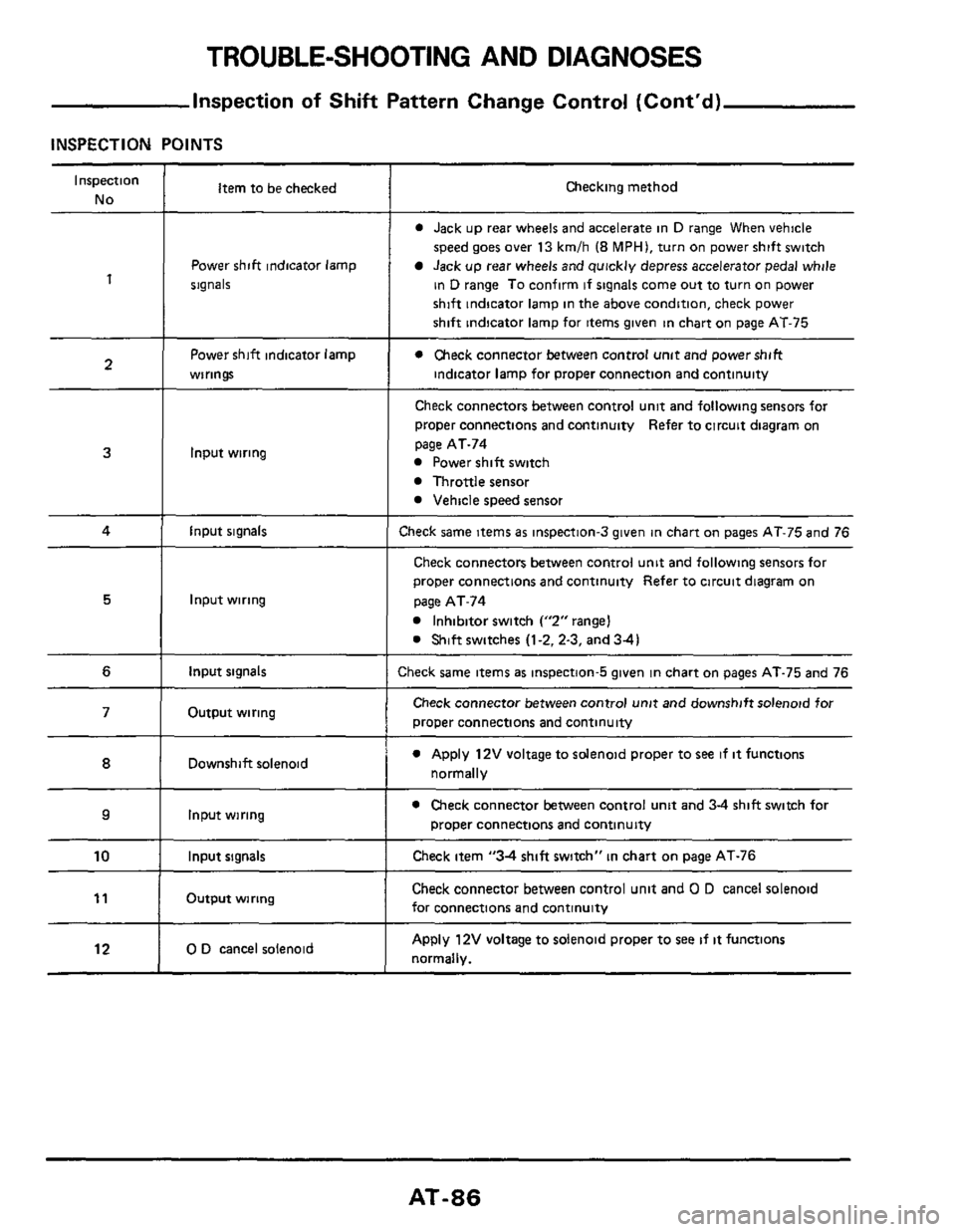
Inspection of Shift Pattern Change Control (Cont'd)
INSPECTION POINTS
Inspection
No
1
2
Item to be checked
Power shift indicator lamp
signals
Power shift indicator lamp
wirings
3
4 I input signals
Input wiring
5
6 I input signals
Input wiring
Output wiring 71
12
Downshift solenoid
Input wiring ~~
0 D cancel
solenoid
IO I Input signals
Output wiring l1 I
Checking method
0 Jack up rear wheels and accelerate in D range When vehicle
speed goes over 13 kmlh (8 MPHI, turn on power shift switch
Jack up rear wheels and quickly depress accelerator pedal while
in
D range To confirm if signals come out to turn on power
shift indicator lamp in the above condition, check power
shift indicator lamp for items given in chart
on page AT-75
0 Check connector between control unit and powershift
indicator lamp for proper connection and continuity
Check connectors between control unit and following sensors foi
proper connections and continuity Refer to circuit diagram on
page AT-74
Power shift switch
Throttle sensor
Vehicle speed sensor
:heck same items as inspection-3 given in chart on pages AT-75 and 76
Check connectors between control unit and following sensors for
proper wnnections and continuity Refer to circuit diagram on
page AT-74
Inhibitor switch Y2"rangeI
0 Shift switches (1-2.2-3, and 34)
:heck same items as inspection-5 given in chart on pages AT-75 and 76
Check connector between control unit and downshift solenoid for
proper connections and continuity
0 Apply 12V voltage to solenoid proper to see if it functions
normally
0 Check connector between control unit and 3-4 shift switch for
proper connections and continuity
Check item "34 shift switch" in chart on page AT-76
Check connector between control unit and 0 D cancel solenoid
for connections and continuity
Apply 12V voltage to solenoid proper to see if it functions
normally.
AT-86
Page 88 of 99
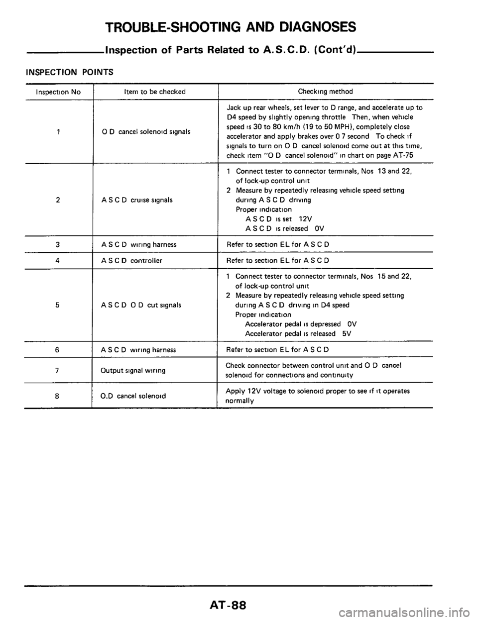
TROUBLE-SHOOTING AND DIAGNOSES
Inspection of Parts Related to A. S. C. D. (Cont’d)
INSPECTION POINTS
Inspection No
1
2
3
4
5
6
7
8
Item to be checked
0 D cancel solenoid signals
A S C D cruise signals
AS C D wiring harness
AS C D controller
AS C D 0 D cut signals
AS C D wiring harness
Output signal wiring
0.D cancel solenoid
Checking method
Jack up rear wheels, set lever to D range, and accelerate up to
D4 speed by slightly opening throttle
Then, when vehicle
speed
is 30 to 80 kmlh (19 to 50 MPH), completely close
accelerator and apply brakes over
0 7 second To check if
signals to turn on 0 D cancel solenoid come out at this time,
check item
“0 D cancel solenoid” in chart on page AT-75
1 Connect tester to connector terminals, Nos 13 and 22,
of lock-up control unit
2 Measure by repeatedly releasing vehicle speed setting
during A S C D driving
Proper indication
ASCD isset 12V
AS C
D is released OV
Refer to section EL for A S C D
Refer to section EL for AS C D
1 Connect tester to connector terminals, Nos 15 and 22,
of lock-up control
unit
2 Measure by repeatedly releasing vehicle speed setting
during AS C
D driving in D4 speed
Proper indication
Accelerator pedal is depressed OV
Accelerator pedal
is released 5V
Refer to section ELfor A S C D
Check connector between control unit and 0 D cancel
solenoid for connections and continuity
Apply 12V voltage to solenoid proper to see if it operates
normally
AT-88
Page 91 of 99
TROUBLE-SHOOTING AND DIAGNOSES
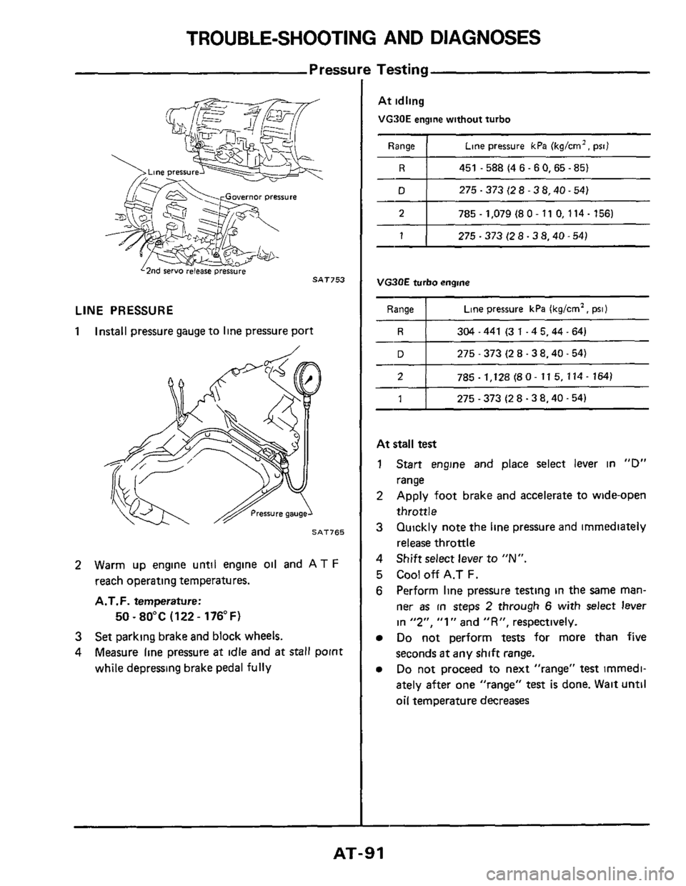
Pressure Testing ~ ~~
2
LINE PRESSURE
1 Install
pressure gauge to line pressure port
785 - 1,128 (8 0- 11 5, 114- 164)
SAT765
1
2 Warm up engine until engine oil and AT F
reach operating temperatures.
A.T.F. temperature:
3 Set parking brake and block wheels.
4 Measure line pressure at idle and at stall point
while depressing brake pedal
fully
50 ~ 80°C (122 - 176°F)
275 - 373 (2 8.3 8.40.54)
At idling
VG90E engine without turbo
Range 1 Line pressure kPa (kg/crn2. psi)
R I 451 -588(46-60,65-85)
D 1 275-373(28-38.40-54)
2 I 785.1,079 (80- 11 0,114- 156)
1 1 275-373(28-38.40-54)
VG3OE turbo engine
Range Line pressure kPa (kg/cm2, psi)
304-441 (31-45.44-64)
275
- 373 (2 8.38.40.54)
At stall test
1 Start engine and place select lever in "D"
range
2 Apply foot brake and accelerate to wide-open
throttle
3 Quickly note the line pressure and immediately
release throttle
4 Shift select lever to "N".
5 Cool off A.T F.
6 Perform line pressure testing in the same man-
ner as in steps 2 through 6 with select lever
in
"2". "1" and "R", respectively.
Do not perform tests for more than five
seconds
at any shift range.
Do not proceed to next "range" test imrnedi-
ately after one "range"
test is done. Wait until
oil temperature decreases
AT-91
Page 93 of 99
TROUBLE-SHOOTING AND DIAGNOSES
Stall
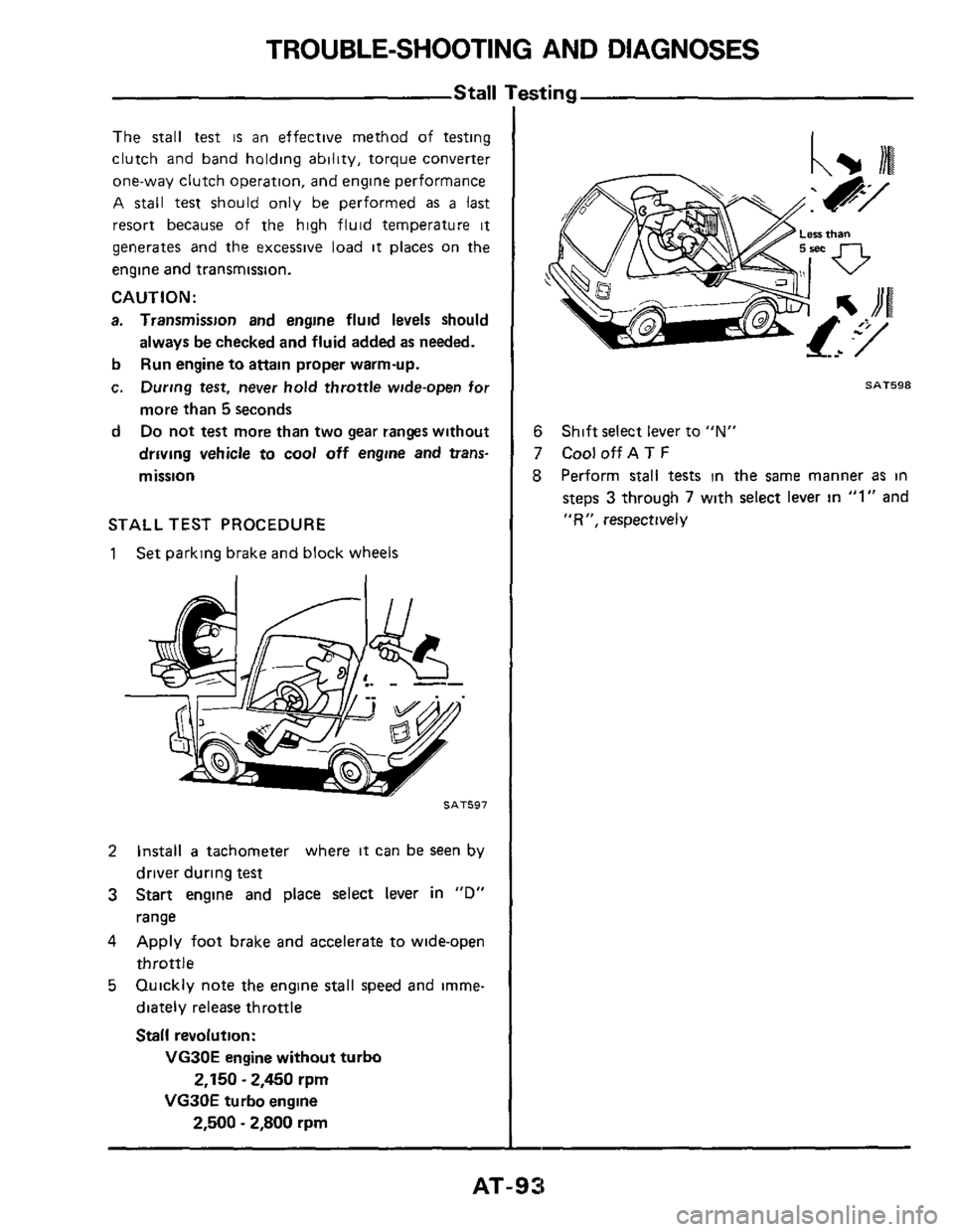
The stall test is an effective method of testing
clutch and band holding ability, torque converter
one-way clutch operation, and engine performance
A
stall test should only be performed as a last
resort because of the high fluid temperature it
generates and the excessive load it places on the
engine and transmission.
CAUTION:
a. Transmission and engine fluid levels should
b
c.
d
always be checked and fluid added as needed.
Run engine to
attain proper warm-up.
During test, never
hold throttle wide-open for
more than
5 seconds
Do not test more than two gear ranges without
driving vehicle to
cool off engine and trans-
mission
STALL TEST PROCEDURE
1 Set parking brake and block wheels
SAT597
2 Install a tachometer where it can be seen by
driver during
test
3 Start engine and place select lever in "D"
range
4 Apply foot brake and accelerate to wide-open
throttle
5 Quickly note the engine stall speed and imme-
diately release throttle
Stall revolution:
VG30E engine without turbo
VG30E turbo engine
2,150 - 2,450 rpm
2,500 - 2,800 rpm
SAT598
6
7 CooloffAT F
8 Perform stall tests in the same manner as in
steps 3 through 7 with select lever in "1" and
"R", respectively
Shift select lever to "N"
AT-93