1984 NISSAN 300ZX brake light
[x] Cancel search: brake lightPage 19 of 99
REMOVAL AND INSTALLATION
installation (Cont'd)
Check inhibitor switch for operation
Check fluid level
in transmission.
Move selector lever through
all positions to be
sure that transmission operates correctly.
With parking brake applied, rotate engine
at
idling Move selector lever through "N" to
"D", to "2". to "1" and to "R" A slight shock
should
be felt by hand gripping selector each
time transmission
is shifted.
Check to be sure
that line pressure is correct.
To do this, refer to Line Pressure Test
Perform stall test.
AT-I 9,
Page 63 of 99
TROUBLE-SHOOTING AND DIAGNOSES
Preliminary Checks
(Prior to Road Testing)
FLUID LEAKAGE
To detect a fluid leak
1) Raise vehicle
2) Clean area suspected of leaking
3) Start engine, apply foot brake, place control
lever in drive, and wait a few minutes
4) Stop engine
5) Check for fresh leakage
FLUID CONDITION
Examine the AT F and note its color, texture,
and odor
1) Dark of Black Fluid
With a burned odor
- Worn friction material
2) Milky Pink Fluid Water Contamination
- Road water entering through filler
tube or breather
3) Varnished Fluid, light to dark brown and
tacky Oxidation
- Over or Underfilling
- Overheating
- Road Testing
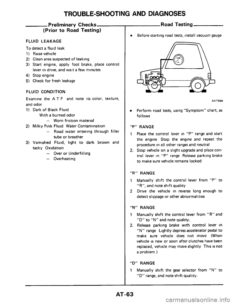
Before starting road tests, install vacuum gauge
SAT596
Perform road tests, using "Symptom" chart, as
follows
"P" RANGE
1 Place the control lever in "P" range and start
the engine Stop the engine and repeat the
procedure in all other ranges and neutral
2. Stop vehicle on a slight upgrade and place con-
trol lever
in "P" range Release parking brake
to make sure vehicle remains locked
"R" RANGE
1 Manually shift the control lever from "P" to
"R", and note shift quality
2 Drive the vehicle in reverse long enough to
detect slippage or other abnormalities
"M" RANGE
1 Manually shift the control lever from "R" and
"D"
to "N" and note quality.
2. Release parking brake with control lever in
"N" range Lightly depress accelerator pedal to
make sure vehicle does not move (When
vehicle
is new or soon after clutches have been
replaced, vehicle may move slightly This
IS not
a problem )
"D" RANGE
1 Manually shift the gear selector from "N" to
"D" range, and note shift quality.
-
AT-63
Page 64 of 99
TROUBLE-SHOOTING AND DIAGNOSES
Road Test
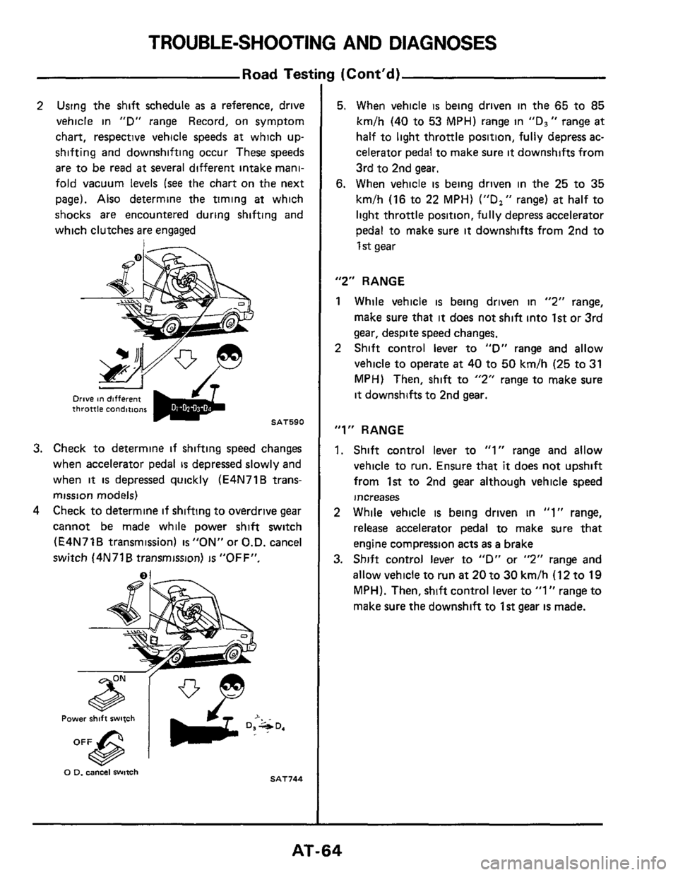
2 Using the shift schedule as a reference, drive
vehicle in
"D" range Record, on symptom
chart, respective vehicle speeds
at which up-
shifting and downshifting occur These speeds
are to be read at several different intake mani-
fold vacuum levels
(see the chart on the next
page). Also determine the timing
at which
shocks are encountered during shifting and
which clutches
are engaged
Drive on different throttle condirtom
SAT590
3. Check to determine if shifting speed changes
when accelerator pedal
is depressed slowly and
when
it is depressed quickly (E4N71B trans-
mission models)
4 Check to determine if shifting to overdrive gear
cannot be made while power shift switch
(E4N71B transmission) is"0N" or
O.D. cancel
switch (4N71
B transmission) is "OFF".
0 0. cancel witch SAT744
3 (Cont'd)
5. When vehicle is being driven in the 65 to 85
km/h (40 to 53 MPH) range in "Ds" range at
half to light throttle position, fully depress ac-
celerator pedal to make sure
it downshifts from
3rd to 2nd
gear.
6. When vehicle is being driven in the 25 to 35
km/h (16 to 22 MPH) ("D," range) at half to
light throttle position, fully depress accelerator
pedal to make sure
it downshifts from 2nd to
1 st gear
"2" RANGE
1 While vehicle is being driven in "2" range,
make sure that
it does not shift into 1st or 3rd
gear, despite speed changes.
2 Shift control lever to "D" range and allow
vehicle to operate
at 40 to 50 km/h (25 to 31
MPH) Then, shift to "2" range to make sure
it downshifts to 2nd gear.
"1" RANGE
1. Shift control lever to "1" range and allow
vehicle to run. Ensure
that it does not upshift
from 1st to 2nd gear although vehicle speed
increases
2 While vehicle is being driven in "1" range,
release accelerator pedal
to make sure that
engine compression acts
as a brake
3. Shift control lever to "D" or "2" range and
allow vehicle to run
at 20 to 30 km/h (12 to 19
MPH). Then, shift control lever to "1" range to
make sure the downshift to 1st gear is made.
AT-64
Page 76 of 99
TROUBLE-SHOOTING AND DIAGNOSES
Inspection of Lock-up Control Unit (Cont'd)
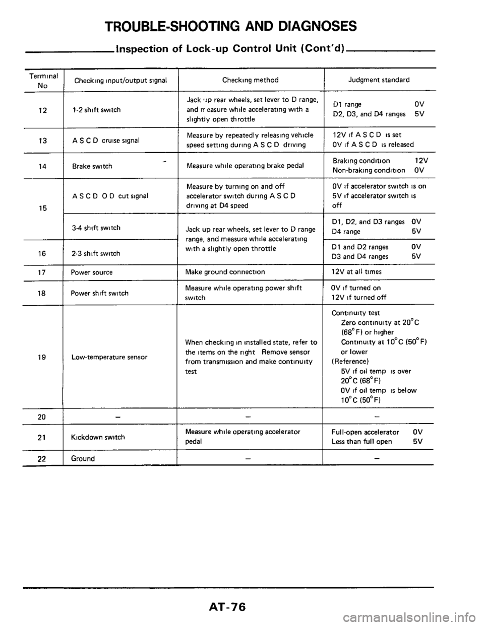
Terminal
No
12
13
14
15
16
17
18
19
20
21
22
___
Checking inputloutput signal
1-2 shift switch
AS C D cruise signal
- Brake switch
A S C 0 0 D cut signal
3-4 shift switch
2-3 shift switch
Power source
Power shift switch
Low-temperature sensor
Kickdown switch
Ground
Checking method
Jack 'JP rear wheels, set lever to D range,
and
ri easure while accelerating with a
slightly open throttle
Measure by repeatedly releasing vehicle
speed setting during
AS C D driving
Measure while operating brake pedal
Measure by turning on and off
accelerator switch during A S C D
driving at D4 speed
Jack up rear wheels, set lever to D range
range,
and measure while accelerating
with
a slightly open throttle
Make ground connection
Measure while operating power shift
switch
When checking in installed state, refer to
the items on the right Remove sensor
from transmission and make continuity
test
Measure while operating acceleratoi
pedal
Judgment standard
D1 range ov
D2. D3, and 04 ranges
12VifASCD
isset
OV if AS C D is released
5V
Braking condition 12v
Non-braking condition OV
OV if accelerator switch is on
5V
if accelerator switch is
off
D1, D2. and D3 ranges OV
D4 range 5v
D1 and D2 ranges
ov
D3 and D4 ranges 5v
12V
at all times
OV if turned on
12V
if turned off
Continuity test
Zero continuity at 20'c
(68OF) or higher
Continuity
at 10°C (50°F)
or lower
(Reference)
5V
if oil temp is over
20°C (68°F)
OV if oil temp
is below
10°C (5OOF)
Ful I-open accelerator OV
Less than
full open 5v
AT-76
Page 82 of 99
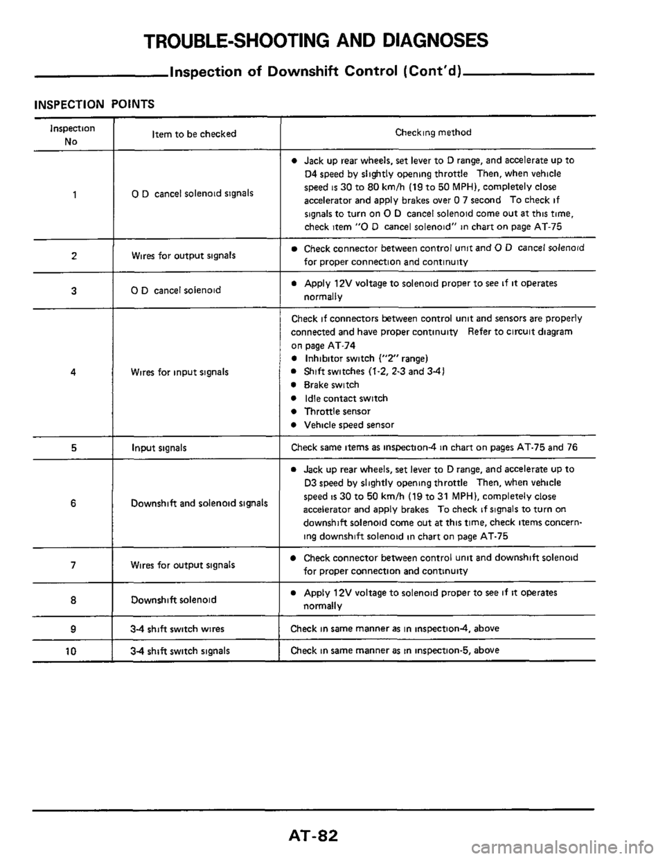
TROUBLE-SHOOTING AND DIAGNOSES
Inspection of Downshift Control (Cont'd)
INSPECTION POINTS
Inspection
No Item to be checked Checking method
0 Jack up rear wheels, set lever to D range, and accelerate up to
04 speed by slightly opening throttle Then, when vehicle
speed
is 30 to 80 kmlh (19 to 50 MPH), completely close
accelerator and apply brakes over
0 7 second To check if
signals to turn on
0 D cancel solenoid come out at this time,
check item
"0 D cancel solenoid" in chart on page AT-75
1 0 D cancel solenoid signals
Wires for output signals Check connector between control unit and 0 D cancel solenoid
for proper connection and continuity
a Apply 12V voltage to solenoid proper to see if it operates
normally
2
3 0 D cancel solenoid
Wires for input signals
Check if connectors between control unit and sensors are properly
connected and have proper continuity Refer to circuit diagram
on page AT-74
0 Inhibitor switch ("2" range)
0 Shift switches (1.2, 2-3 and 3-41
0 Brake switch
0 Idle contact switch
0 Throttle sensor
0 Vehicle speed sensor
4
5 Input signals Check same items as inspection4 in chart on pages AT-75 and 76
0 Jack up rear wheels, set lever to D range, and accelerate up to
D3 speed by slightly opening throttle Then, when vehicle
speed
is 30 to 50 kmlh (19 to 31 MPH), completely close
accelerator and apply brakes To check
if signals to turn on
downshift solenoid come out
at this time, check items concern-
ing downshift solenoid in chart on page AT-75
6 Downshift and solenoid signals
Check connector between control unit and downshift solenoid
for proper connection and continuity 7 Wires for output signals
Downshift solenoid
___ ~~ ~~~
0 Apply 12V voltage to solenoid proper to see if it operates
normally 8
9 34 shift switch wires Check in same manner as in inspectiond, above
Check in same manner
as in inspection-5, above 10 34 shift switch signals
AT-82
Page 88 of 99
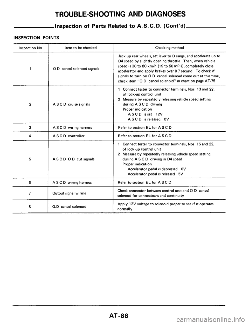
TROUBLE-SHOOTING AND DIAGNOSES
Inspection of Parts Related to A. S. C. D. (Cont’d)
INSPECTION POINTS
Inspection No
1
2
3
4
5
6
7
8
Item to be checked
0 D cancel solenoid signals
A S C D cruise signals
AS C D wiring harness
AS C D controller
AS C D 0 D cut signals
AS C D wiring harness
Output signal wiring
0.D cancel solenoid
Checking method
Jack up rear wheels, set lever to D range, and accelerate up to
D4 speed by slightly opening throttle
Then, when vehicle
speed
is 30 to 80 kmlh (19 to 50 MPH), completely close
accelerator and apply brakes over
0 7 second To check if
signals to turn on 0 D cancel solenoid come out at this time,
check item
“0 D cancel solenoid” in chart on page AT-75
1 Connect tester to connector terminals, Nos 13 and 22,
of lock-up control unit
2 Measure by repeatedly releasing vehicle speed setting
during A S C D driving
Proper indication
ASCD isset 12V
AS C
D is released OV
Refer to section EL for A S C D
Refer to section EL for AS C D
1 Connect tester to connector terminals, Nos 15 and 22,
of lock-up control
unit
2 Measure by repeatedly releasing vehicle speed setting
during AS C
D driving in D4 speed
Proper indication
Accelerator pedal is depressed OV
Accelerator pedal
is released 5V
Refer to section ELfor A S C D
Check connector between control unit and 0 D cancel
solenoid for connections and continuity
Apply 12V voltage to solenoid proper to see if it operates
normally
AT-88