Page 49 of 99
Page 50 of 99
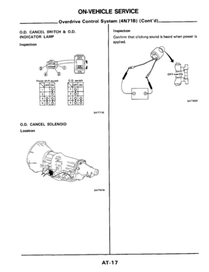
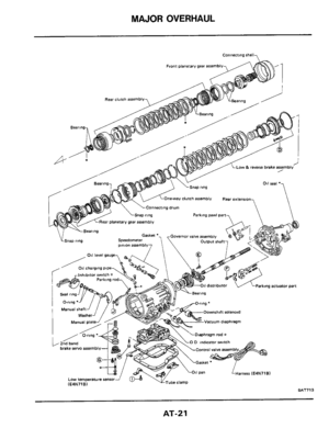
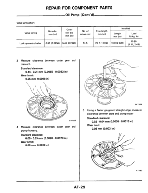
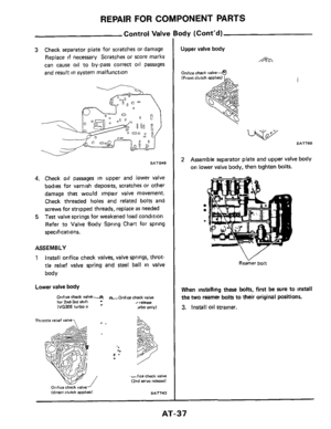
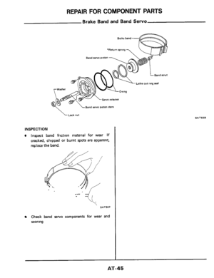
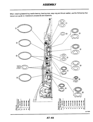
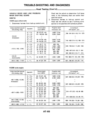
ASSEMBLY
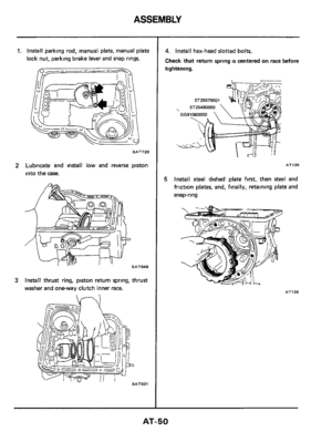
1. Install parking rod, manual plate, manual plate
lock nut, parking brake lever and snap rings.
Ob/-- 0 - 0- 7
SAT720
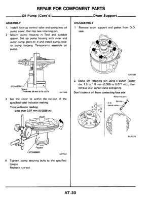
2 Lubricate and install low and reverse piston
into the case.
SATM8
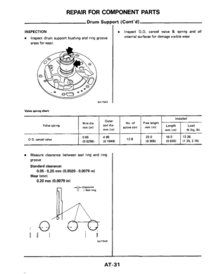
3 Install thrust ring, piston return spring, thrust
washer and oneway clutch inner race.
4. Install hex-head slotted bolts.
Check that return spring is centered on race before
tightening.
AT135
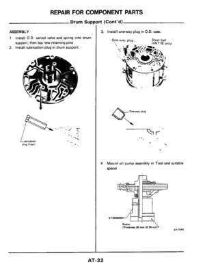
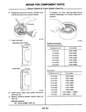
5 Install steel dished plate first, then steel and
friction plates, and, finally, retaining plate and
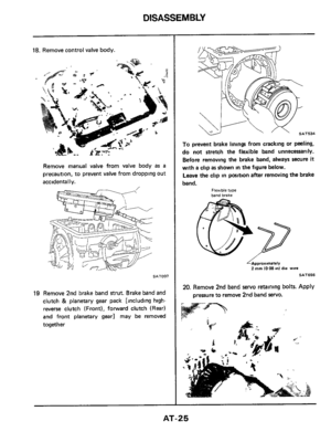
snap-ring
AT129
AT-50
Page 51 of 99
90EOX-f9!31& rn&OX-L99
LE
&O&OX-f99LE
ZOEOX-f99LE
lOEOX-L99L&
OOEOX-f991&
(W90)8Zl
(96V
0) 9 Zl
(88V 0) VZL
(08V 0) Z Zl
(ZfV 0) 0 ZL
l99P 0) 8 11
30EW
9090X-L99LE I (9VE0) 88 I
P09OX-f99 LE 16&& 0) 9 8
EOIiOX-f99L& 1
zwox-f 99 LE I LEE 0) P 8 I oqinl 30E~A (EZE 0) Z 8
1090X-f991& I ISLEO) 08 1
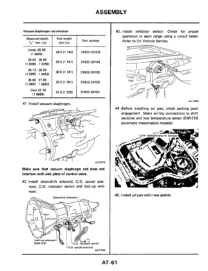
009ox-f 99 LE (LO& 0) 8 f
Page 52 of 99
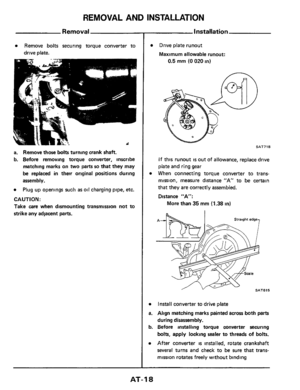
ASSEMBLY
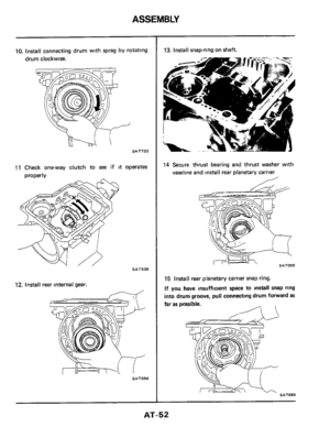
10. Install connecting drum with sprag by rotating
drum clockwise.
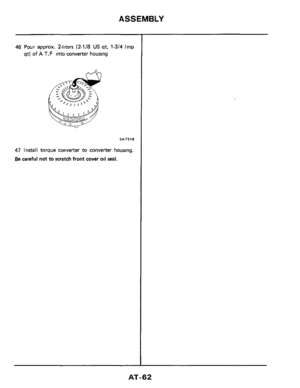
SAT732
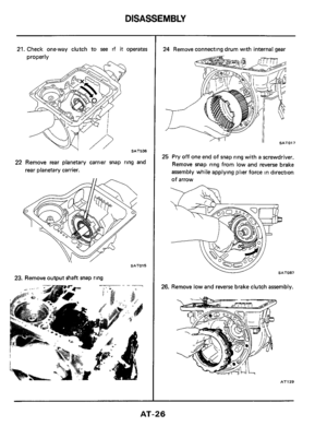
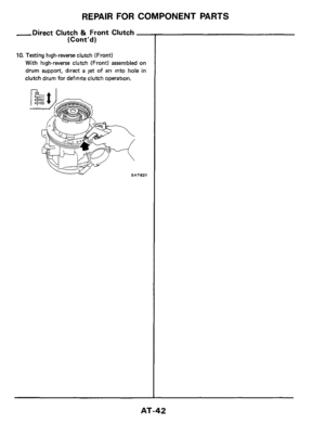
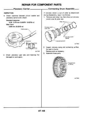
11 Check one-way clutch to see if it operates
orooerlv
SAT536
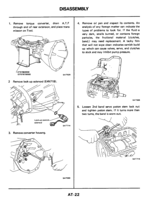
12. Install rear internal gear.
-
SAT054
13. Install snap-ring on shaft.
14 Secure thrust bearing and thrust washer with
vaseline and install rear planetary carrier
SAT055
15 Install rear planetary carrier snap ring.
If you have insufficient space to install snap ring
into drum groove, pull connecting drum forward
as
far as possible.
SAT056 SAT056
AT-52
Page 53 of 99
ASSEMBLY
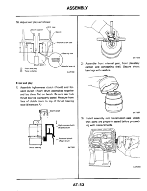
16. Adjust end play as follows:
rO 0 case
SAT733 5 Total end play
Front end play
1) Assemble high-reverse clutch (Front) and for-
ward clutch (Rear) drum assemblies together
and lay them
flat on bench. Be sure rear hub
thrust bearing
is properly seated Measure from
face of clutch drum to top
of thrust bearing
race (dimension A)
Hgh-reverse clutch
(Front) drum
,Forward clutch
(Rear1 drum
Thrust bearing 4 SAT061
SAT062
2) Assemble front internal gear, front planetary
carrier and connecting shell. Secure thrust
bearings with vaseline.
L4 SAT057
3) Install assembly into transmission case Check
that
parts are properly seated before proceed-
ing with measurements.
SAT058
AT-53
Page 54 of 99
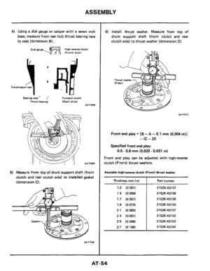
ASSEMBLY
4) Using a dial gauge or caliper with a seven inch
base, measure from rear hub thrust bearing race
to case (dimension
6).
Dial gauge- High-reverse clutch IFrontl drum
Bearing race ’ / Forward clutch Thrust bearing (Rear1 drum SAT059
SAT060
5) Measure from top of drum support shaft (front
clutch and rear clutch side) to installed gasket
(dimension
C).
SAT734
6) Install thrust washer. Measure from top of
drum support shaft (front clutch and rear
clutch side) to thrust washer (dimension
D)
SAT571
Front end play = [B - A - 0.1 rnrn (0.004 in)]
- (C - D)
Specified front end play:
0.5 - 0.8 mm (0.020 - 0.031 in)
Front end play can be adjusted with high-reverse
clutch (Front) thrust washers.
Available high-reverse clutch (Front) thrust washer
Thickness rnrn (in)
1.3 (0051)
15 (0059)
1.7 (0067)
1.9 (0075)
2 1 (0083)
23 (0091)
2 5 (0098)
2.7 (0 106)
Part number
31 528-XO107
31 528-X0106
31 528-XOlO5
31528-XOlOO
31526-XOl Ol
31528-X0102
31 528-XO103
31 528-XO104
AT-54
Page 55 of 99
ASSEMBLY ~
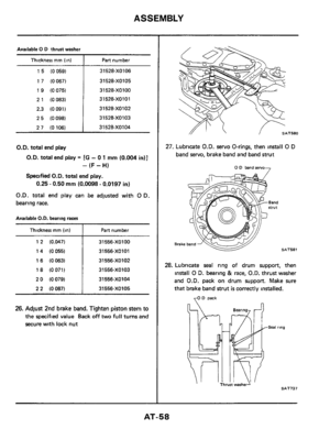
Total
end play
Totql end play = [B - 0 1 mm (0.004 in)] - C
Specified total end play:
0 25 - 0.50 mm
(0.0098 - 0.0197 in)
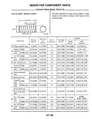
Total end play can be adjusted with bearing race
Available oil pump cover bearing race
Thickness rnm (in)
1 2 (0 0471
1
4 (0055)
16 (0.0631
18 (0071)
20
(0 079)
22
(00871
Pan number
31556-X0100 31556-XOlO1
31 556-X0102
31 556-XO103
31 556-XO104
31 556-XO105
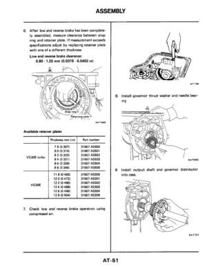
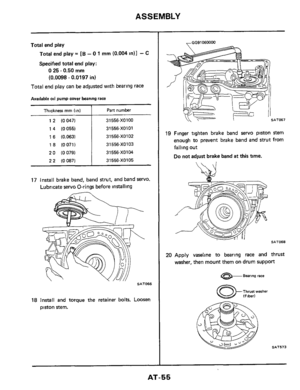
17 Install brake band, band strut, and band servo.
Lubricate servo O-rings before installing
SAT066
18 Install and torque the retainer bolts. Loosen
piston stem.
,GG91060000
19 Finger tighten brake band servo piston stem
enough to prevent brake band and
strut from
falling out
Do not adjust brake band at this time.
SAT068
20 Apply vaseline to bearing race and thrust
washer, then mount them
on drum support
e- Bearing race
SA1573
AT-55
Page 56 of 99

ASSEMBLY
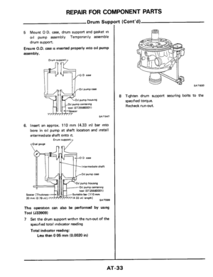
21. Mount drum support gasket @ on drum
support
after coating with vaseline. Apply
A
T.F to O-ring of drum support Align drum
support with
0.D case to transmission case
and install
identification point of gasket
Between 011 pump and 0 0 case @ Between drum SUPPOR to transmission care (@
SAT624
22. Apply A T.F to O-ring of drum support, then
Before installing drum support and O.D. case on
transmission
case, ensure that they have been
centered properly. Refer to Component
Parts for
Drum Support.
23 Temporarily tighten 0.D case using two con-
install drum support and O.D. case
verter housing securing bolts.
Spacer 115mm 10.59 in) thick1
rOD case
I I
\TIM Case SAT574
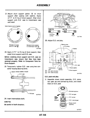
24. Insert intermediate shaft.
E4N71 B:
Be careful of shaft direction.
I-
*
-
Grinding surface Front Front SAT754
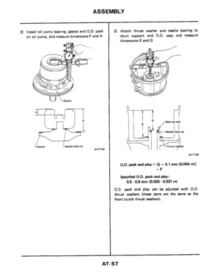
25. Adjust O.D. end play.
Bearing race
Oil pump
Gasket
bearing Drum suppon case
@I 0 0 pack end play
@ 0 D total end play SAT576
O.D. pack end play
1) Assemble direct clutch assembly, 0 D plane-
tary gear
set and connecting drum, and install
them on
O.D. pack
Connecting drum
- 0 0 run gear
-0 D carrier
0 0 internal gear
Direct clutch assembly
SAT577 u
AT-56


8Zl
(96V
0) 9 Zl
(88V 0) VZL
(08V 0) Z Zl
(ZfV 0) 0 ZL
l99P 0) 8 11
30EW
9090X-L99LE I (9VE0) 88 I
P09OX-f")

 Assemble high-reverse clutch (Front) and for-
ward clutch (Rear) drum assemblies together
an")
 Using a dial gauge or caliper with a seven inch
base, measure from rear hub thrust bearing race
to case (dimension
6).
Dial gauge- High-reverse clutch IFrontl drum
Bearing")
![NISSAN 300ZX 1984 Z31 Automatic Transmission Workshop Manual ASSEMBLY ~
Total
end play
Totql end play = [B - 0 1 mm (0.004 in)] - C
Specified total end play:
0 25 - 0.50 mm
(0.0098 - 0.0197 in)
Total end play can be adjusted with bearing race
Avail](/manual-img/5/563/w960_563-54.png "NISSAN 300ZX 1984 Z31 Automatic Transmission Workshop Manual ASSEMBLY ~
Total
end play
Totql end play = [B - 0 1 mm (0.004 in)] - C
Specified total end play:
0 25 - 0.50 mm
(0.0098 - 0.0197 in)
Total end play can be adjusted with bearing race
Avail")