Page 81 of 99
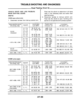
TROUBLE-SHOOTING AND DIAGNOSES
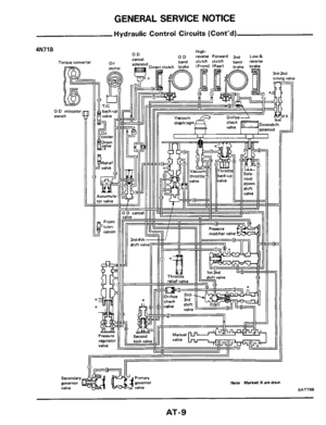
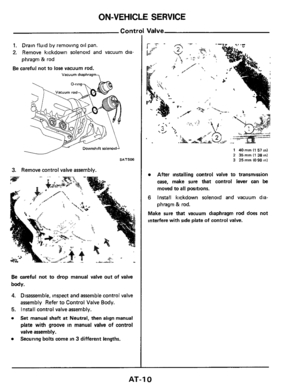
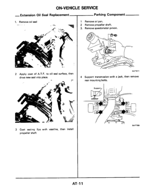
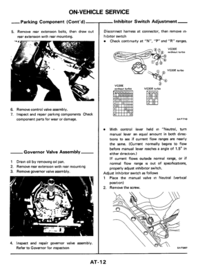
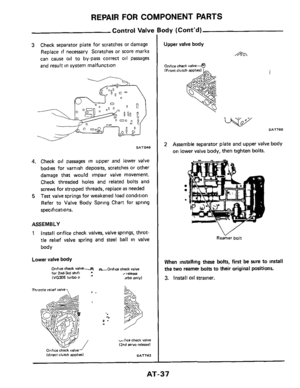
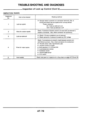
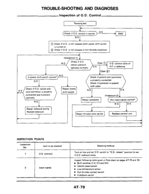
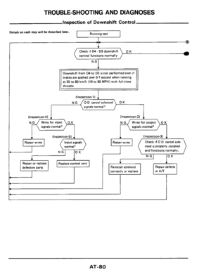
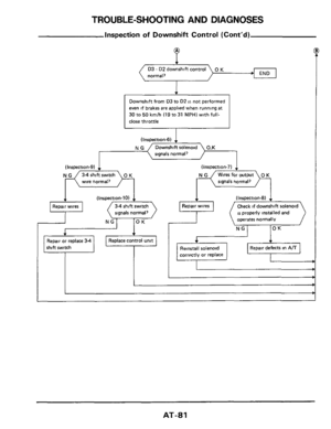
Inspection of Downshift Control (Cont‘d)
D3 - D2 downshift control
normal, 0 K END
Downshift from D3 to D2 is, not performed
even
if brakes are applied when running at
30 to 50 km/h (19 to 31 MPH) with full-
close throttle
(Inspection-6) 1
, NG(-G*
signals normal?
(Inspection-9) 4
N G 34 shift switch
wire normal?
1 Inspection-10)
signals normal7
~~nspection-7) 1
signals normal)
‘1
Repair or replace 34
shift switch
Check if downshift solenoid
IS properly installed and
operates normally
corrrctly or replace
AT-81
Page 82 of 99

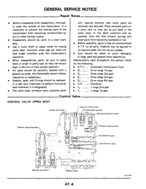
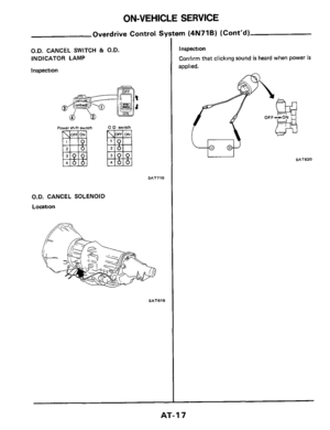
INSPECTION POINTS
Inspection
No Item to be checked Checking method
0 Jack up rear wheels, set lever to D range, and a")
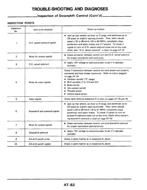
TROUBLE-SHOOTING AND DIAGNOSES
Inspection of Downshift Control (Cont'd)
INSPECTION POINTS
Inspection
No Item to be checked Checking method
0 Jack up rear wheels, set lever to D range, and accelerate up to
04 speed by slightly opening throttle Then, when vehicle
speed
is 30 to 80 kmlh (19 to 50 MPH), completely close
accelerator and apply brakes over
0 7 second To check if
signals to turn on
0 D cancel solenoid come out at this time,
check item
"0 D cancel solenoid" in chart on page AT-75
1 0 D cancel solenoid signals
Wires for output signals Check connector between control unit and 0 D cancel solenoid
for proper connection and continuity
a Apply 12V voltage to solenoid proper to see if it operates
normally
2
3 0 D cancel solenoid
Wires for input signals
Check if connectors between control unit and sensors are properly
connected and have proper continuity Refer to circuit diagram
on page AT-74
0 Inhibitor switch ("2" range)
0 Shift switches (1.2, 2-3 and 3-41
0 Brake switch
0 Idle contact switch
0 Throttle sensor
0 Vehicle speed sensor
4
5 Input signals Check same items as inspection4 in chart on pages AT-75 and 76
0 Jack up rear wheels, set lever to D range, and accelerate up to
D3 speed by slightly opening throttle Then, when vehicle
speed
is 30 to 50 kmlh (19 to 31 MPH), completely close
accelerator and apply brakes To check
if signals to turn on
downshift solenoid come out
at this time, check items concern-
ing downshift solenoid in chart on page AT-75
6 Downshift and solenoid signals
Check connector between control unit and downshift solenoid
for proper connection and continuity 7 Wires for output signals
Downshift solenoid
___ ~~ ~~~
0 Apply 12V voltage to solenoid proper to see if it operates
normally 8
9 34 shift switch wires Check in same manner as in inspectiond, above
Check in same manner
as in inspection-5, above 10 34 shift switch signals
AT-82
Page 83 of 99
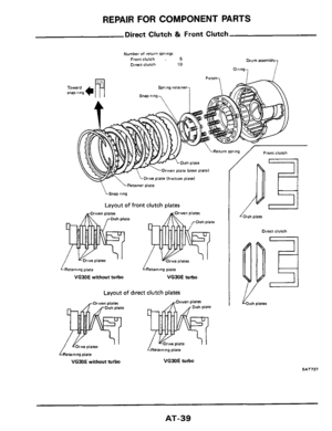
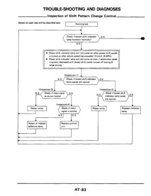
TROUBLE-SHOOTING AND DIAGNOSES
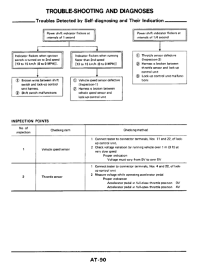
Inspection of Shift Pattern Change Control
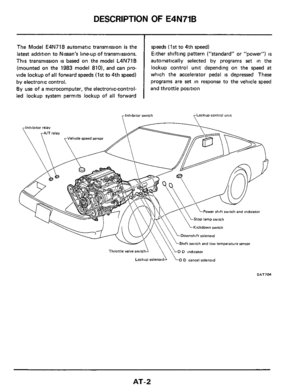
Details on each step will be described later
I
lamp function normally,
is turned on after vehicle speed has exceeded 13 kmh (8 MPH)
0 Power shift indicator lamp will not come on even if accelerator pedal
is quickly depressed with power shift switch turned off during D
range driving
dlns pection-1) ~
,
Check if power shift indicator
lamp signals are normal
(Inspection-31
wires are normal
(Inspection-2) . I
Check if power shift
are normal
(~nspection-41 1
signal is normal
I I
defective parts
Replace control
I I I I I I
AT-83
Page 84 of 99
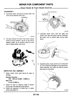
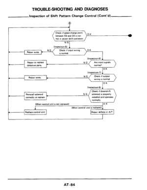
TROUBLE-SHOOTING AND DIAGNOSES
(Inspection-5)
Check if input wiring OK
L is normal Repair wires
(Inspection-6)
Repair or replace NG Are input signals
defective parts. normal? 4
OK
(Inspection-7)
Inspection of Shift Pattern Change Control (Cont'd)
(Inspection-8) 1
Check if downshift
Reinstall solenoid solenoid
is properly
correctly or replace installed and operates
normally
4
(When control unit is not replaced) OK
1 (When control unit is replaced)
4 Replace control unit
I 4
OK Check if speed change point
between
02 and D3 is nor-
mal in power shift operation
I N G.1
I. Repair wires.
AT-84
Page 85 of 99
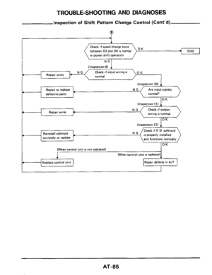
TROUBLE-SHOOTING AND DIAGNOSES
Inspection of Shift Pattern Change Control (Cont’d)
9
END OK Check if speed change point
between
D3 and D4 is normal
in power shift operation
(Inspection-9)
Check if input wiring is
normal
(Inspection-101
normal,
NG Repair wires
Repair or replace
defective pans
(Inspection.111 1
Check if output
wiring
is normal
(Inspection-12) 1
Check if 0 D solenoid
and functions normally Reinstall solenoid
correctly or replace
(When control unit is not replaced1
(When control unit is replaced)
Replace control unit
I-I-”7
Repair defects in A/T
P
AT-85
Page 86 of 99

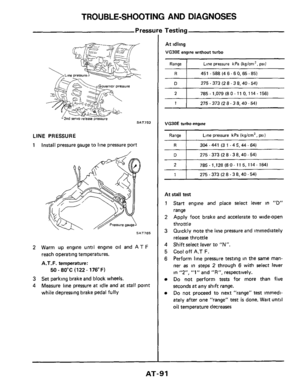
INSPECTION POINTS
Inspection
No
1
2
Item to be checked
Power shift indicator lamp
signals
Power shift")
TROUBLE-SHOOTING AND DIAGNOSES
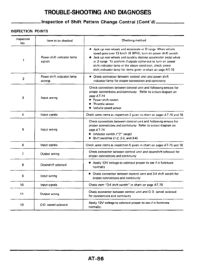
Inspection of Shift Pattern Change Control (Cont'd)
INSPECTION POINTS
Inspection
No
1
2
Item to be checked
Power shift indicator lamp
signals
Power shift indicator lamp
wirings
3
4 I input signals
Input wiring
5
6 I input signals
Input wiring
Output wiring 71
12
Downshift solenoid
Input wiring ~~
0 D cancel
solenoid
IO I Input signals
Output wiring l1 I
Checking method
0 Jack up rear wheels and accelerate in D range When vehicle
speed goes over 13 kmlh (8 MPHI, turn on power shift switch
Jack up rear wheels and quickly depress accelerator pedal while
in
D range To confirm if signals come out to turn on power
shift indicator lamp in the above condition, check power
shift indicator lamp for items given in chart
on page AT-75
0 Check connector between control unit and powershift
indicator lamp for proper connection and continuity
Check connectors between control unit and following sensors foi
proper connections and continuity Refer to circuit diagram on
page AT-74
Power shift switch
Throttle sensor
Vehicle speed sensor
:heck same items as inspection-3 given in chart on pages AT-75 and 76
Check connectors between control unit and following sensors for
proper wnnections and continuity Refer to circuit diagram on
page AT-74
Inhibitor switch Y2"rangeI
0 Shift switches (1-2.2-3, and 34)
:heck same items as inspection-5 given in chart on pages AT-75 and 76
Check connector between control unit and downshift solenoid for
proper connections and continuity
0 Apply 12V voltage to solenoid proper to see if it functions
normally
0 Check connector between control unit and 3-4 shift switch for
proper connections and continuity
Check item "34 shift switch" in chart on page AT-76
Check connector between control unit and 0 D cancel solenoid
for connections and continuity
Apply 12V voltage to solenoid proper to see if it functions
normally.
AT-86
Page 87 of 99
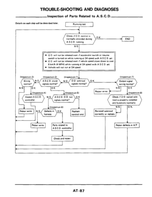
TROUBLE-SHOOTING AND DIAGNOSES
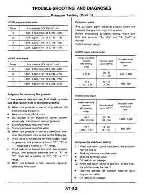
Inspection of Parts Related to A. S. C. D.
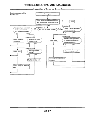
I Running test Details on each step will be described later.
I
normally provided during
AS C D running
switch is turned on while running at D4 speed with AS C D set
0 D will not be released even if vehicle speed slows down to over
6 kmlh (4 MPHI while running at D4 speed with AS C D set
e Vehicle will not run at D4 speed
(Inspection-7)
Output signal
wiring normal?
(Inspection-3) (Inspection-2) (Inspection-1 I
0 D solenoid
signals normal,
wz) NGI 10 K lOK
controller signals normal?
Check if 0 D cancel sole-
noid
is properly installed
harness control unit correctly or replace.
Parts related to
AS C D controller
Check and repair
Repair defects in A/T
T
AT-87
Page 88 of 99

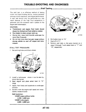
INSPECTION POINTS
Inspection No
1
2
3
4
5
6
7
8
Item to be checked
0 D cancel solenoid signals
A")
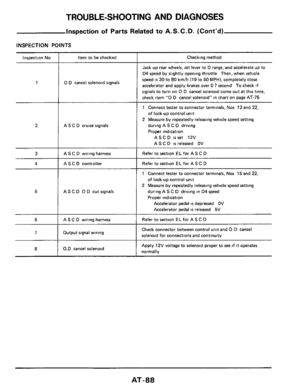
TROUBLE-SHOOTING AND DIAGNOSES
Inspection of Parts Related to A. S. C. D. (Cont’d)
INSPECTION POINTS
Inspection No
1
2
3
4
5
6
7
8
Item to be checked
0 D cancel solenoid signals
A S C D cruise signals
AS C D wiring harness
AS C D controller
AS C D 0 D cut signals
AS C D wiring harness
Output signal wiring
0.D cancel solenoid
Checking method
Jack up rear wheels, set lever to D range, and accelerate up to
D4 speed by slightly opening throttle
Then, when vehicle
speed
is 30 to 80 kmlh (19 to 50 MPH), completely close
accelerator and apply brakes over
0 7 second To check if
signals to turn on 0 D cancel solenoid come out at this time,
check item
“0 D cancel solenoid” in chart on page AT-75
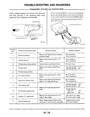
1 Connect tester to connector terminals, Nos 13 and 22,
of lock-up control unit
2 Measure by repeatedly releasing vehicle speed setting
during A S C D driving
Proper indication
ASCD isset 12V
AS C
D is released OV
Refer to section EL for A S C D
Refer to section EL for AS C D
1 Connect tester to connector terminals, Nos 15 and 22,
of lock-up control
unit
2 Measure by repeatedly releasing vehicle speed setting
during AS C
D driving in D4 speed
Proper indication
Accelerator pedal is depressed OV
Accelerator pedal
is released 5V
Refer to section ELfor A S C D
Check connector between control unit and 0 D cancel
solenoid for connections and continuity
Apply 12V voltage to solenoid proper to see if it operates
normally
AT-88

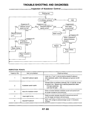

D3 - D2 downshift control
normal, 0 K END
Downshift from D3 to D2 is, not performed
even
if brakes are applied when")


Check if input wiring OK
L is normal Repair wires
(Inspection-6)
Repair or replace NG Are input signals
defective parts. normal? 4
OK
(Inspe")

9
END OK Check if speed change point
between
D3 and D4 is normal
in power shift operation
(Inspection-")
