Page 10 of 99
ON-VEHICLE SERVICE
Contrl
1. Drain fluid by removing oil pan.
2. Remove kickdown solenoid and vacuum dia
phragm
23 rod
Be careful not to lose vacuum rod.
Vacuum diaphragm
SAT506
3. Remove control valve assembly.
Be careful not to drop manual valve out of valve
body.
4. Disassemble, inspect and assemble control valve
assembly Refer to Control Valve Body.
5. Install control valve assembly.
0 Set manual shaft at Neutral, then align manual
plate with groove in manual valve of control
valve assembly.
Securing bolts come
in 3 different lengths. 0
1 40 mm I1 51 in) 2 35 mm (1 38 in1 3 25mm1098mI
After installing control valve to transmission
case, make sure that control lever can be
moved to all positions.
6 Install kickdown solenoid and vacuum dia-
phragm
& rod.
Make sure that vacuum diaphragm rod does not
interfere with side plate
of control valve.
AT-I 0
Page 60 of 99
ASSEMBLY
Air check point
Governor feed (From
valve) Forward clutch Control
LOW & reverse
brake
SAT586
37 Check that parking pawl, pin, spring and
washer are assembled correctly.
rWasher
SAT739
38. Install rear extension
39. Install control valve assembly. Be sure manual
valve
is in alignment with selector pin Tighten
control valve
body attaching bolts.
Securing bolt comes in three different lengths.
1 40 mm I1 57 ml
2 35 mm I1 38 m) 3 25 mm IO 98 1n1
After installing control valve to transmission case,
make sure that control lever can be moved to all
positions.
40 Before installing vacuum diaphragm valve,
measure depth of hole in which
it is inserted
This measurement determines correct rod
length to ensure proper performance.
"L ' Depth
Vacuum Diaphragm rod , throttle;alve / Valve body ride plate
AT-60
Page 98 of 99

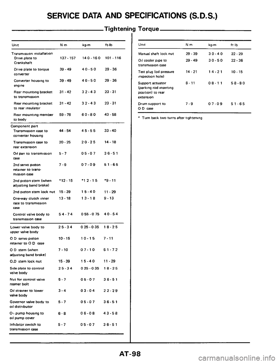
SERVICE DATA AND SPECIFICATIONS (S.D.S.)
Tig hteni
Untt Nm kg-m ft-lb
Transmission mrtallation Drive plate to 137-157 140-160 101.116
Crankshaft
Drive plate to torque 39.49 4 0.5 0 29.36
converter
Converter housing to
39 - 49 4 0 - 5 0 29 - 36
engme
Rearmountingbracket
31 -42 32-43 23-31
to transmissnon
Rear mounting bracket
31 -42 3 2 - 4 3 23 - 31
to rear insulator
Rear mounting
member 59 - 78 6 0.8 0 43.58
to body
Camponent part
Transmission case to
converter housing
Transmission
case IO
rear extension
Od pan to transmissJon
case
2nd servo piston
retainer to trans- mission case
2nd piston stem (when adjusting band brake)
2nd mston stem lock nut
Onway clutch inner
race to transmission
Control valve body to
transmission case
Wle
44.54
20.25
5-7
7-9
'12-15
15-39
13-18
54-74
45-55 33-40
20-25 14-18
05-07 36-51
07-09 51-65
'12-15 *9.11
15-40 11-29
13-18 9-13
055-075 40-54
Lower valve body to 25-34 025-035 18-25
upper valve body
0 D servo pinon 10- 15 10-15 7-11
retainer to 0 D case
0 D stem (when 7-10 07-10 51-72
adjusting band brake)
0.D stem lock nut 15-39 15-40 11-29
Side Plate to Control 25-34 025-035 18-25 valve body
Nut for control valve 5-7 05-07 36-51
reamer bolt
011 strainer to lower 3-4 03-04 22-29
valve body
Governor MIM body to 5 - 7 05-07 36-51
011 distrtbutor
O*, pump housing to 6-8 06-08 43-58 011 pump cover
Inhibitor switch
to 5-7 05-07 36-51
transmission case
I Torque
U"lt Nm kgm ft Ib
Manual shaft lock nut 29.39 30-40 22-29
011 cooler pipe to 29 - 49 30-50 22-36 transmission case
Test plug
lo11 pressure 14-21 14-21 10-15 inspection hole)
Support actuator 8- 11 08-11 58-80
(parking rod inserting
position) to
rear
extension
Drum support to 7-9 07-09 51-65 0 D case
* Turn back two turns after tightening