Page 10 of 99
ON-VEHICLE SERVICE
Contrl
1. Drain fluid by removing oil pan.
2. Remove kickdown solenoid and vacuum dia
phragm
23 rod
Be careful not to lose vacuum rod.
Vacuum diaphragm
SAT506
3. Remove control valve assembly.
Be careful not to drop manual valve out of valve
body.
4. Disassemble, inspect and assemble control valve
assembly Refer to Control Valve Body.
5. Install control valve assembly.
0 Set manual shaft at Neutral, then align manual
plate with groove in manual valve of control
valve assembly.
Securing bolts come
in 3 different lengths. 0
1 40 mm I1 51 in) 2 35 mm (1 38 in1 3 25mm1098mI
After installing control valve to transmission
case, make sure that control lever can be
moved to all positions.
6 Install kickdown solenoid and vacuum dia-
phragm
& rod.
Make sure that vacuum diaphragm rod does not
interfere with side plate
of control valve.
AT-I 0
Page 18 of 99
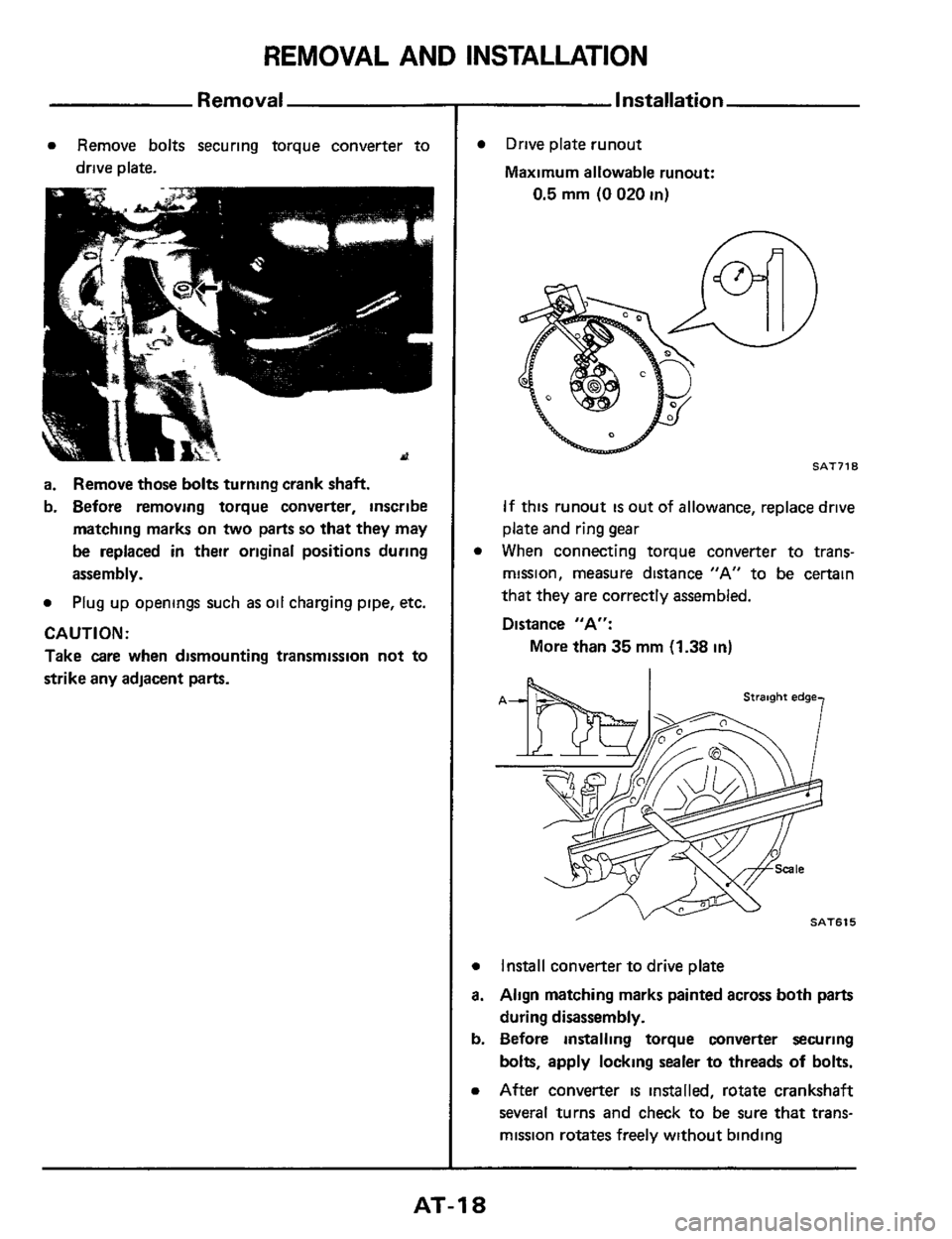
REMOVAL AND INSTALLATION
Removal
a Remove bolts securing torque converter to
drive plate.
a. Remove those bolts turning crank shaft.
b. Before removing torque converter, inscribe
matching marks on
two parts so that they may
be replaced in their original positions during
assembly.
a Plug up openings such as oil charging pipe, etc.
CAUTl ON :
Take care when dismounting transmission not to
strike any adjacent
parts.
Installation
0
a
a.
b.
a
Drive plate runout
Maximum allowable runout:
0.5 mm (0 020 in)
n
SAT718
If this runout is out of allowance, replace drive
plate and ring gear
When connecting torque converter to trans-
mission, measure distance "A" to be certain
that they are correctly assembled.
Distance "A":
More than
35 mm (1.38 in)
Install converter to drive plate
Align matching marks painted across both parts
during disassembly.
Before installing torque converter securing
bolts, apply locking sealer to threads
of bolts.
After converter is installed, rotate crankshaft
several turns and check to be sure that trans-
mission rotates freely without binding
AT-I 8
Page 25 of 99
DISASSEMBLY
18. Remove control valve body.
Remove manual valve from valve body as a
precaution, to prevent valve from dropping out
accidentally.
SAT007
19 Remove 2nd brake band strut. Brake band and
clutch
& planetary gear pack [Including high-
reverse clutch (Front), forward clutch (Rear)
and front
planetary gear] may be removed
together
To prevent brake linings from cracking or peeling,
do not stretch the flexible band unnecessarily.
Before removing the brake band, always secure
it
with a clip as shown in the figure below.
Leave the clip
in position after removing the brake
band.
Flexible type band brake
2 mm 1008 In) dia wire
SAT656
20. Remove 2nd band servo retalning bolts. Apply
pressure to remove 2nd band =NO.
AT-25
Page 30 of 99
REPAIR FOR COMPONENT PARTS
Oil Pump (Cont'd)
ASSEMBLY
1. Install lock-up control valve and spring into oil
pump cover, then tap new retaining pin.
2 Mount pump housing in Tool and suitable
spacer. Set up pump housing with inner and
outer pump gears on
it and install pump cover
to pump housing Temporarily assemble
oil
pump.
sar-0
3 Set the cover to within the run-out of the
specified total indicator reading.
Total indicator reading:
Less than 0.07 mm (0 0028 in)
SAT541 &25580001
4 Tighten pump securing bolts to the specified
torque Recheck run-out
Drum Support
DISASSEMBLY
1 Remove drum support and gasket from O.D.
case.
SATW
2. Stake off retaining pin using a punch [outer
dia.
1.5 to 1.8 mm (0.059 to 0.071 in)], then
remove
O.D. cancel valve and spring
Don't stake it off from contacting face side
7 Retaining pin
00
AT-30
Page 33 of 99
REPAIR FOR COMPONENT PARTS
Drum Support (Cont'd)
5 Mount 0 D. case, drum support and gasket in
oil pump assembly Temporarily assemble
drum support.
Ensure O.D. case is inserted properly into oil pump
assembly.
0 0 case
I pump cafe 11 An
011 pump centering
SAT547
6. Insert an approx. 110 mm (4.33 in) bar into
bore in oil pump
at shaft location and install
intermediate shaft onto
it.
intermediate shaft
011 pump centering
tool lST25580001)
Suitablebar [llOmm
SAT599 20 mm IO 79 dl
This operation can also be performed by using
Tool
(533909)
7 Set the drum support within the run-out of the
specified total indicator reading
Total indicator reading:
Less than 0 05 mm (0.0020 in)
8 Tighten drum support securing bolts to the
specified torque.
Recheck run-out.
AT-33
Page 41 of 99
REPAIR FOR COMPONENT PARTS
Thickness mm (in)
50(0197)
5
2 (0 2051
54(02131
5
6 (0 2201
5 8 (0 2281
6 0 IO 236)
6 2 10.244)
-
Direct Clutch & FI
Part number
31567-XZ900
31567-XZ901
31 567-X2902
31 567-XZ903
31 567-X2904
31 567-X2905
31567-XZ906
6 Reassemble spring and retainer. Reinstall snap
ring. Be sure snap ring IS properly seated.
Thickness mm (in1
5 8 IO 228)
6 0 IO 236)
6.2 (0 244)
6 4 (0 252)
6 6 IO 260)
6 8 IO 268)
7 0 IO 276)
-
SAT028
Part number
31567.X2904
31567-XZ905
31567-XZ906
31507-X8600
31507-X8601
31537-XZ800
31537-X2801
7. Install dish plate
High-reverse clutch (Front)
Direct clutch
SAT554
8. Install driven plates, drive plates, and secure
with snap ring.
9. Measure clearance between retainer plate and
snap ring
Specified clearance:
1.6. 1.8 mm (0.063.0.071 in)
it Clutch (Cont'd)
If necessary, try other retaining plates having
different thicknesses until correct clearance
IS
o bta i ned
Direct clutch
turbo 7 2 IO 283)
7410291)
AT-41
Page 52 of 99
ASSEMBLY
10. Install connecting drum with sprag by rotating
drum clockwise.
SAT732
11 Check one-way clutch to see if it operates
orooerlv
SAT536
12. Install rear internal gear.
-
SAT054
13. Install snap-ring on shaft.
14 Secure thrust bearing and thrust washer with
vaseline and install rear planetary carrier
SAT055
15 Install rear planetary carrier snap ring.
If you have insufficient space to install snap ring
into drum groove, pull connecting drum forward
as
far as possible.
SAT056 SAT056
AT-52
Page 53 of 99
ASSEMBLY
16. Adjust end play as follows:
rO 0 case
SAT733 5 Total end play
Front end play
1) Assemble high-reverse clutch (Front) and for-
ward clutch (Rear) drum assemblies together
and lay them
flat on bench. Be sure rear hub
thrust bearing
is properly seated Measure from
face of clutch drum to top
of thrust bearing
race (dimension A)
Hgh-reverse clutch
(Front) drum
,Forward clutch
(Rear1 drum
Thrust bearing 4 SAT061
SAT062
2) Assemble front internal gear, front planetary
carrier and connecting shell. Secure thrust
bearings with vaseline.
L4 SAT057
3) Install assembly into transmission case Check
that
parts are properly seated before proceed-
ing with measurements.
SAT058
AT-53


