Page 845 of 875
GM – CAMARO 1982-1992 – Repair Guide (Checked by WxMax) 845
STABILIZER (SWAY) BAR
REMOVAL & INSTALLATION
Fig. 1: Stabilizer end links
1. Raise and support the rear end on jackstands.
2. Disconnect the end link bolts.
3. Remove the U-bolts and insulators.
4. Installation is the reverse of re moval. Please refer to the torque
specifications chart.
STEERING COLUMN
WARNING - Before attempting any repairs involving the steering wheel or
disassembly of it, ensure that the Supple mental Inflatable Restraint (Air Bag)
system is properly disarmed.
Page 859 of 875

GM – CAMARO 1982-1992 – Repair Guide (Checked by WxMax) 859
REMOVAL & INSTALLATION
PITMAN ARM
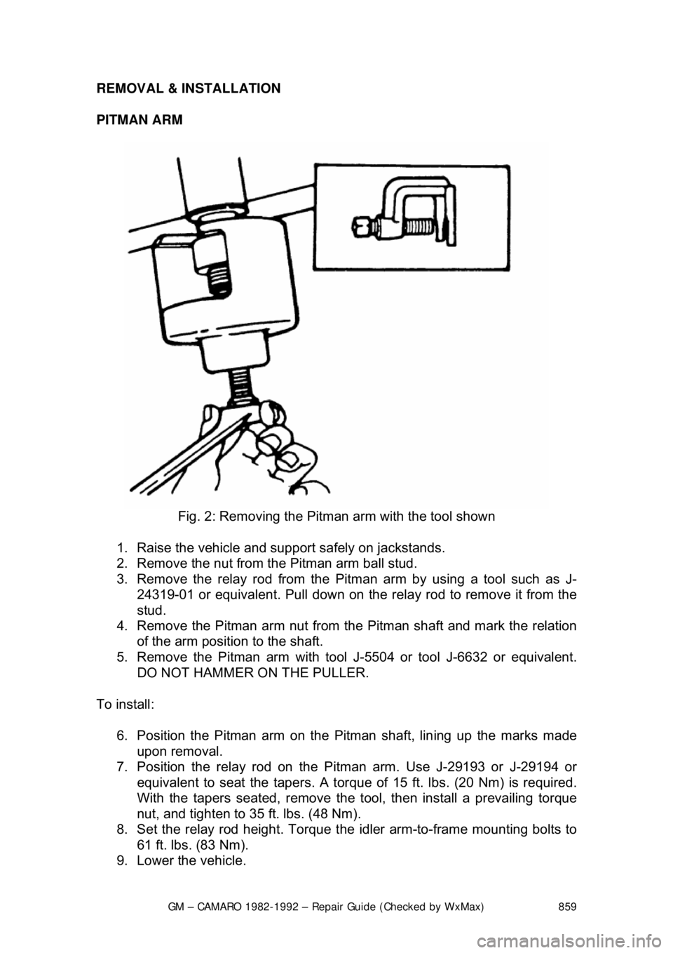
Fig. 2: Removing the Pitman arm with the tool shown
1. Raise the vehicle and support safely on jackstands.
2. Remove the nut from the Pitman arm ball stud.
3. Remove the relay rod from the Pitman arm by us ing a tool such as J-
24319-01 or equivalent. Pull down on the relay rod to remove it from the
stud.
4. Remove the Pitman arm nut from the Pitman shaft and mark the relation
of the arm position to the shaft.
5. Remove the Pitman arm with tool J-5504 or tool J-6632 or equivalent.
DO NOT HAMMER ON THE PULLER.
To install: 6. Position the Pitman arm on the Pitman shaft, lin ing up the marks made
upon removal.
7. Position the relay rod on the Pi tman arm. Use J-29193 or J-29194 or
equivalent to seat the t apers. A torque of 15 ft. lb s. (20 Nm) is required.
With the tapers seated, remove the t ool, then install a prevailing torque
nut, and tighten to 35 ft. lbs. (48 Nm).
8. Set the relay rod height. Torque t he idler arm-to-frame mounting bolts to
61 ft. lbs. (83 Nm).
9. Lower the vehicle.
Page 860 of 875
GM – CAMARO 1982-1992 – Repair Guide (Checked by WxMax) 860
Idler Arm
1. Raise the vehicle and support safely on jackstands.
2. Remove the idler arm to fr ame nuts, washers, and bolts.
3. Remove the nut from the idle r arm to relay rod ball stud.
4. Remove the relay rod from t he idler arm by using J-24319-01 or
equivalent.
5. Remove the idler arm.
To install: 6. Position the idler arm on the fr ame and LOOSELY install the mounting
bolts, washers and nuts.
7. Install the relay rod to the idler a rm, making certain seal is on the stud.
Use J-29193 or J-29194 or equivalent to seat the tapers. A torque of 15
ft. lbs. (20 Nm) is required. With the tapers seated, remove the tool, then
install a prevailing torque nut, and ti ghten to 35 ft. lbs. (48 Nm).
8. Set the relay rod height. Torque t he idler arm-to-frame mounting bolts to
61 ft. lbs. (83 Nm).
9. Lower the vehicle.
RELAY ROD
Fig. 3: Removing the relay rod-to-tie rod nut
Page 862 of 875

GM – CAMARO 1982-1992 – Repair Guide (Checked by WxMax) 862
During production, the installe
d position of the relay rod is carefully controlled to
assure that the rod is at the proper height. Both the left end and the right end of
the relay rod must be held at the sa me height. The side-to-side height is
controlled by adjusting the pos ition of the idler arm
Whenever disconnecting the rela y rod assembly, it is important to first scribe the
position of the idler arm-to-frame, and to reinstall the idler arm in the same
position. Be sure to prevent the idler support from turning in the bushing, since
that motion could result in improper relay rod height.
Whenever replacing the relay rod, or the idler arm, or the Pitman arm, it is
mandatory to establish the correct height.
1. Raise the vehicle and support safely on jackstands.
2. Remove the inner ends of the tie rods from the relay rod.
3. Remove the nut from the relay rod ball stud attachment at Pitman arm.
4. Detach the relay rod from the Pitm an arm by using tool such as J-24319-
01 or equivalent. Shift the steering lin kage as required to free the Pitman
arm from the relay rod.
5. Remove the nut from the idler arm and remove the relay rod from the
idler arm.
To install: 6. Install the relay rod to idler arm, ma king certain idler stud seal is in place.
Use J-29193 or J-29194 or equivalent to seat the tapers. A torque of 15
ft. lbs. (20 Nm) is required. With the tapers seated, remove the tool, then
install a prevailing torque nut, and ti ghten to 35 ft. lbs. (48 Nm).
7. Raise the end of the rod and insta ll on the Pitman arm. Use J-29193 or J-
29194 or equivalent to seat the tapers. A torque of 15 ft. lbs. (20 Nm) is
required. With the tapers seated, remove the tool, then install a prevailing
torque nut, and tighten to 35 ft. lbs. (48 Nm).
8. Install the tie rod ends to the re lay rod. Lubricate the tie rod ends.
9. Install the damper , if equipped.
10. Set the relay rod height. Torque t he idler arm-to-frame mounting bolts to
61 ft. lbs. (83 Nm).
11. Lower the vehicle.
12. Check and, if necessary, adjust front end alignment.
Page 864 of 875

GM – CAMARO 1982-1992 – Repair Guide (Checked by WxMax) 864
8. Rotate both inner and out
er tie rod housings rearward to the limit of ball
joint travel before tightening clamps . Make sure clamp slots and sleeve
slots are aligned before tightening cl amps. Make sure tightened bolts will
be in horizontal position to 45 degrees upward (in the forward direction)
when the tie rod is in its normal positi on. Make sure the tie rod end stays
in position relative to the rod duri ng the tightening operation. Tighten the
clamps, and then return the assembly to the center of its travel.
9. Install ball stud nuts and torque to 35 ft. lbs. (47 Nm) Then tighten (do not
loosen) further as required to align cotter pin holes in studs and nuts.
Install new cotter pins.
10. Lubricate new tie rod ends and lower the vehicle.
POWER STEERING GEAR
ADJUSTMENTS
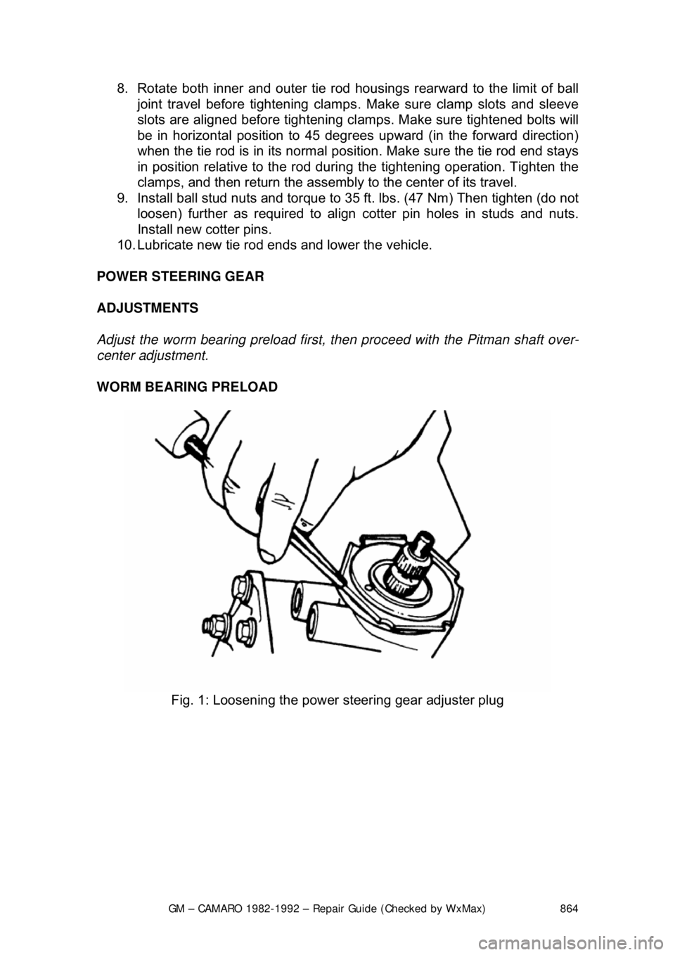
Adjust the worm bearing preload first, then proceed with the Pitman shaft over-
center adjustment.
WORM BEARING PRELOAD
Fig. 1: Loosening the power steering gear adjuster plug
Page 867 of 875
GM – CAMARO 1982-1992 – Repair Guide (Checked by WxMax) 867
Pitman Shaft Over-Center
Fig. 5: Aligning the stub sha ft parallel with the top cover
Fig. 6: Checking the over-center rotational torque
1. Disconnect the negative battery cable.
2. Remove the steering gear.
Page 868 of 875

GM – CAMARO 1982-1992 – Repair Guide (Checked by WxMax) 868
3. Rotate the stub shaft and drain the
power steering fluid into a suitable
container.
4. Turn the Pitman shaft adjuster screw counterclockwise until fully
extended, then turn back 1 full turn.
5. Rotate the stub shaft from stop-to -stop and count the number of turns.
6. Starting at either stop, turn the stub shaft back half the total number of
turns. This is the "Center" posit ion of the gear. When the gear is
centered, the flat on the stub sha ft should face upward and be parallel
with the side cover, and the master spline on the Pitman shaft should be\
in line with the adjuster screw.
7. Rotate the stub shaft 45 degrees each side of the center using a suitable
torque wrench with the hand le in the vertical position. Record the worm
bearing preload measured on or near the center gear position.
8. Adjust the over-center drag torque by loosening the adjuster locknut and
turning the Pitman shaft adjuster screw clockwise until the correct drag
torque is obtained: Add 6-10 inch lbs. (0.7-1.1 Nm) of torque to the
previously measured wo rm bearing preload torque. Tighten the adjuster
locknut to 20 ft. lbs. (27 Nm). Prev ent the adjuster screw from turning
while tightening the adju ster screw locknut.
9. Install the steering gear and c onnect the negative battery cable.
REMOVAL & INSTALLATION
Fig. 7: Steering gear removal
1. Disconnect the negative battery cabl e. Remove the coupling shield.
2. Remove the retaining bolts at t he steering coupling to steering shaft
flange.
3. Remove the Pitman arm nut and wa sher. Mark the relation of the arm
position to the shaft.