1982 CHEVROLET CAMARO torque
[x] Cancel search: torquePage 9 of 875

GM – CAMARO 1982-1992 – Repair Guide (Checked by WxMax) 9
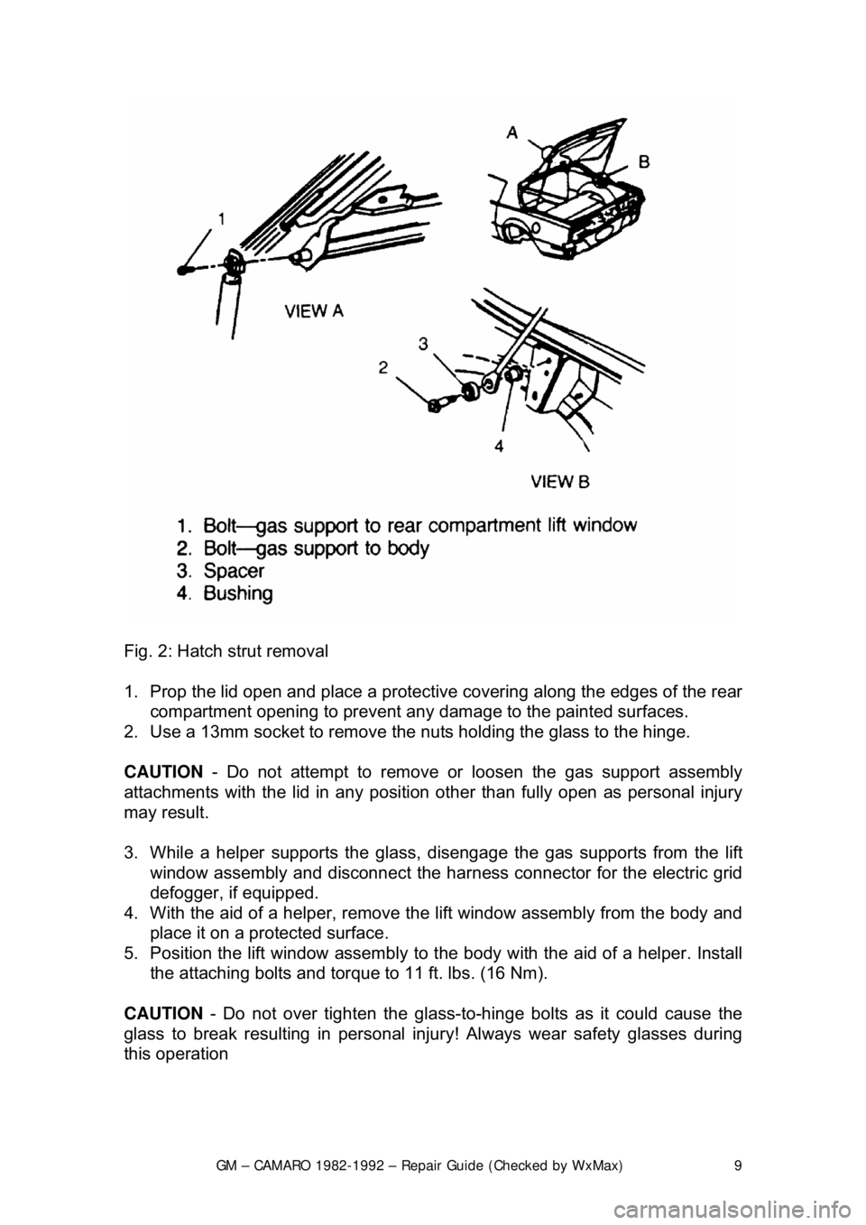
Fig. 2: Hatch strut removal
1. Prop the lid open and place a protective covering along the edges of the rear
compartment opening to prevent any damage to the painted surfaces.
2. Use a 13mm socket to remove the nuts holding the glass to the hinge.
CAUTION - Do not attempt to remove or loosen the gas support assembly
attachments with the lid in any position other than fully open as person\
al injury
may result.
3. While a helper supports the glass, disengage the gas supports from the lift
window assembly and disconnect the har ness connector for the electric grid
defogger, if equipped.
4. With the aid of a helper, remove the lift window assembly from the body and
place it on a protected surface.
5. Position the lift window assembly to t he body with the aid of a helper. Install
the attaching bolts and torque to 11 ft. lbs. (16 Nm).
CAUTION - Do not over tighten the glass-to -hinge bolts as it could cause the
glass to break resulting in personal injury! Always wear safety glasses during
this operation
Page 11 of 875

GM – CAMARO 1982-1992 – Repair Guide (Checked by WxMax) 11
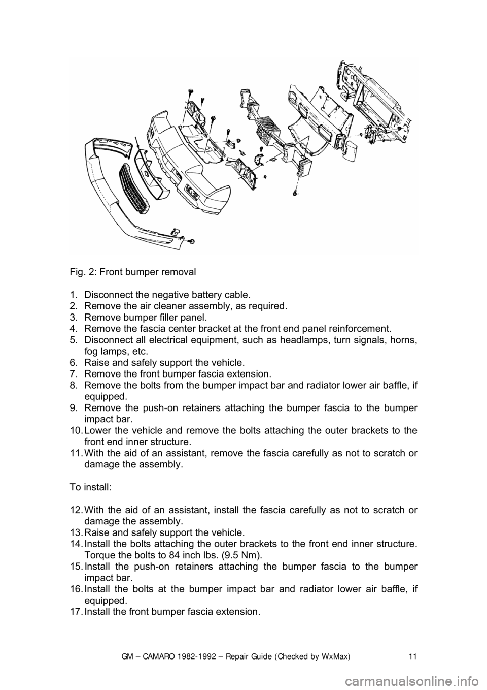
Fig. 2: Front bumper removal
1. Disconnect the negative battery cable.
2. Remove the air cleaner assembly, as required.
3. Remove bumper filler panel.
4. Remove the fascia center bracket at the front end panel reinforcement.
5. Disconnect all electrical equipment, su ch as headlamps, turn signals, horns,
fog lamps, etc.
6. Raise and safely support the vehicle.
7. Remove the front bumper fascia extension.
8. Remove the bolts from the bumper impac t bar and radiator lower air baffle, if
equipped.
9. Remove the push-on retainers attach ing the bumper fascia to the bumper
impact bar.
10. Lower the vehicle and remove the bolt s attaching the outer brackets to the
front end inner structure.
11. With the aid of an assistant, remove t he fascia carefully as not to scratch or
damage the assembly.
To install:
12. With the aid of an assistant, install t he fascia carefully as not to scratch or
damage the assembly.
13. Raise and safely support the vehicle.
14. Install the bolts attachi ng the outer brackets to the front end inner structure.
Torque the bolts to 84 inch lbs. (9.5 Nm).
15. Install the push-on retainers atta ching the bumper fascia to the bumper
impact bar.
16. Install the bolts at t he bumper impact bar and radiat or lower air baffle, if
equipped.
17. Install the front bum per fascia extension.
Page 14 of 875

GM – CAMARO 1982-1992 – Repair Guide (Checked by WxMax) 14
2. Remove the mirror base-to-door outer
panel stud nuts, remove the cable
from the clip and remove the mirror and cable assembly from the door.
3. Position the mirror onto the door ma king sure the mirror gasket is properly
aligned on the door outer panel.
4. Install the cable onto the clip and install the mirror base-to-door outer panel
stud nuts. Torque to 72 inch lbs. (8 Nm).
5. Install the inner panel wate r deflector and door trim panel.
6. Install the mirror remote control bezel.
POWER OPERATED MIRRORS
Disconnect the negative battery terminal and, from the door trim panel side,
remove the remote control mirror bezel , release and remove the door panel.
1. Disconnect wire harness connection from t he remote mirror electrical switch.
2. Peel back water deflect or enough to detach the har ness from the retaining
tabs in the door.
3. Remove the mirror base-to-door stud nuts and lift mirror housing and
harness assembly from the door.
To install:
5. feed the mirror harness through the do or along with the mirror assembly.
Install the mirror base-to- door stud nuts and tighten.
6. Connect the mirror wire harness and install the water deflector.
7. Connect the wire harness connection to the remote mirror electrical switch.
8. Install the door panel and install the remote control mirror bezel.
9. Connect the negative battery terminal.
Page 34 of 875

GM – CAMARO 1982-1992 – Repair Guide (Checked by WxMax) 34
REAR LIFTGATE PULL-DOWN UNIT
REMOVAL & INSTALLATION
Fig. 1: Pull-down lock unit
1. Open the rear hatch. Disconnec t the negative battery cable.
2. Remove the rear trim panel. Disconnec t the electrical connector and remove
the attaching screws.
3. Disconnect the unit lock cable co nnection from the lock cylinder.
4. Remove the unit.
5. Installation is the reverse of the re moval procedure. Torque the screws to 18
ft. lbs. (24 Nm).
ADJUSTMENT
Adjust the unit as necessary fo r proper lock striker engagement.
DOOR WINDOW
REMOVAL & INSTALLATION
1. Remove the door trim panel and the inner panel water deflector.
2. Raise the window to the half-up position.
3. Punch out the center pins of the gl ass to sash channel attaching rivets.
4. Remove the rear guide channel through the rear access hole.
5. Remove the up stop.
6. Using a
1/4 in. (6mm) drill bit, drill out the atta ching rivets on sash channel.
7. Raise the glass to remove from the sash channel and remove the glass from
the door.
Page 36 of 875

GM – CAMARO 1982-1992 – Repair Guide (Checked by WxMax) 36
2. Raise the window to half-
up position and hold in place by inserting a rubber
wedge door stops at the front and r ear of the window between window and
inner panel.
3. Remove the rear guide channel and inner panel cam channel.
4. Punch out the center pins of the r egulator rivets; then drill out the rivets
using a
1/4 in. (6mm) drill bit.
5. Move the regulator rear ward and disconnect wire harness from the motor (if
equipped). Disengage the roller on the re gulator lift arm from glass sash
channel.
6. Remove the regulator thr ough the rear access hole.
CAUTION - If electric motor removal from t he regulator is required, the sector
gear must be locked in positi on. The regulator lift arm is under tension from the
counterbalance spring and could cause personal injury if the sector gear is not
locked in position.
7. Drill a hole through the r egulator sector gear and backplate and install a bolt
and nut to lock the sector gear in position.
8. Using a
3/16 in. (5mm) drill bit, drill out the motor attaching rivets and remove
the motor from the regulator.
To install:
9. To install the motor to the regulator, use a rivet tool J-29022 or equivalent,
and install
3/16 in. (5mm) rivets or 3/16 in. (5mm) nuts and bolts. Remove bolt
and nut used to secure the sector gear in position.
10. Place the regulator th rough the rear access hole into the door inner panel. If
electric regulator is being installed, connect the wire connector to motor prior
to installing the regulat or to the inner panel.
11. Locate the lift arm roller in to the glass sash channel.
12. Using rivet tool J-29022 or equivalent, rivet the regulator to the inner panel
of the door using
1/4 in. (6mm) 1/2 in. (13mm) aluminum peel type rivets (part
No. 9436175 or equivalent). If rivet tool is not available, use the following nut
and bolt method:
a. Install U-clips on the regulator at the attaching locations. Be sure to
install the clips with clinch nuts on the outboard side of the regulator.
b. Locate the regulator in the door inner panel. If the electric regulator is
being installed, connect the wire connec tor to the regulator motor.
c. Locate the lift arm roller in the glass sash channel.
d. Align the regulator with clinch nuts to holes in the inner panel.
e. Attach the regulator (and mo tor) to the door inner panel with
1/4-20 x 1/2
in. screws (part No. 9 419723 or equivalent) into 1/4 in. (6mm) nuts with
integral washers. Tighten the screw to 90-125 inch lbs. (10-14 Nm)
torque.
13. Install the inner panel cam channel and rear guide channel.
14. Remove the rubber wedge door stops at the front and rear of the window
between window and inner panel.
15. Install the inner panel water deflector and the door trim panel.
Page 41 of 875

GM – CAMARO 1982-1992 – Repair Guide (Checked by WxMax) 41
1. Determine the rear view mirror suppor
t position on the windshield. Support is
to be located at the center of the glass 271/8 in. (69cm) from the base of the
glass to the base of the support.
2. Mark the location on the outside of the glass with wax pencil or crayon.
Make a larger diameter circle around t he mirror support circle on the outside
of the glass surface.
3. On the inside of the glass surface, clean the large circle with a paper towel
and domestic scouring cleanser, gla ss cleaning solution or polishing
compound. Rub until the area is comple tely clean and dry. When dry, clean
the area with an alcohol saturated paper towel to remove any traces of
scouring powder or cleaning solution from this area.
4. With a piece of fine grit (No. 320 or No. 360) emery cloth or sandpaper, sand
the bonding surface of the new rear view mirror support or factory installed
support. If original rear view mirror support is to be reused, all traces of the
factory installed adhesive must be re moved prior to reinstallation.
5. Wipe the sanded mirror support with a clean paper towel saturated with alcohol and allow it to dry.
6. Follow the directions on the manufac turer's kit to prepare the rear view
mirror support prior to inst allation on the glass.
7. Properly position the support to it s premarked location, with rounded end
pointed upward, press the support agai nst the glass for 30-60 seconds,
exerting steady pressure against the gla ss. After five minutes, any excess
adhesive may be removed with an alcohol moistened paper towel or glass
cleaning solution.
8. Install the mirror.
SEATS
REMOVAL & INSTALLATION
1. Operate the seat to the full-forwar d position. If a six-way power seat is
operable, operate the seat to the full-forward and up positions. Where
necessary to gain access to the adjuste r-to-floor pan attaching nuts, remove
the adjuster rear foot covers and/or carpet retainers.
2. Remove the track covers where nec essary; then remove the adjuster-to-
floor pan rear attaching nuts. Operate t he seat to the full-rearward position.
Remove the adjuster front foot covers ; then remove the adjuster-to-floor pan
front attaching nuts.
3. Remove the seat assembly from the car.
4. Check that both seat adjusters ar e parallel and in phase with each other.
5. Install the adjuster-to- floor pan attaching nuts by moving the seat forward
and rearward and torque nuts to 15-21 ft. lbs. (20-28 Nm).
6. Check the operation of the seat a ssembly to full limits of travel.
Page 57 of 875

GM – CAMARO 1982-1992 – Repair Guide (Checked by WxMax) 57
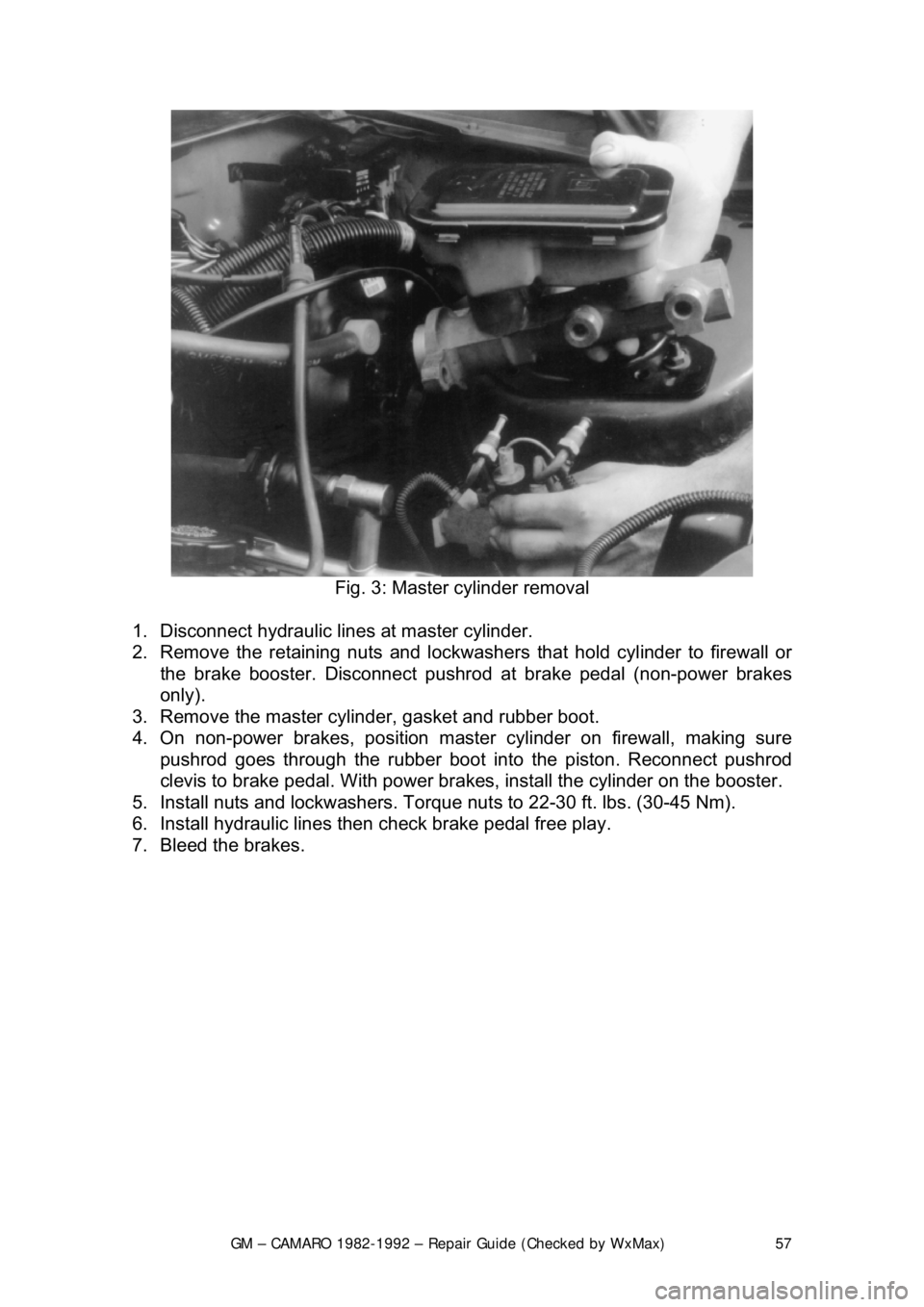
Fig. 3: Master cylinder removal
1. Disconnect hydraulic lines at master cylinder.
2. Remove the retaining nuts and lockwasher s that hold cylinder to firewall or
the brake booster. Disconnect pushrod at brake pedal (non-power brakes
only).
3. Remove the master cylinder, gasket and rubber boot.
4. On non-power brakes, position master cylinder on firewall, making sure pushrod goes through the rubber boot in to the piston. Reconnect pushrod
clevis to brake pedal. With power brakes, install the cylinder on the bo\
oster.
5. Install nuts and lockwashers. Torque nut s to 22-30 ft. lbs. (30-45 Nm).
6. Install hydraulic lines t hen check brake pedal free play.
7. Bleed the brakes.
Page 82 of 875

GM – CAMARO 1982-1992 – Repair Guide (Checked by WxMax) 82
Avoid inhaling any dust from
any brake surface! When cleaning brake surfaces,
use a commercially available brake cleaning fluid.
1. Remove
2/3 of the brake fluid from the mast er cylinder. Raise the vehicle and
remove the wheel.
2. Place a C-clamp across the caliper, positioned on the brake pads. Tighten it
until the piston is forced into its bore.
3. Remove the C-clamp. Remove the bolt holding the brake hose to the caliper.
4. Remove the Allen head caliper mounting bolts. Inspect them for corrosion
and replace them if necessary. Remove the caliper.
To install:
5. Position the caliper with the brake pad installed and install Allen head caliper
mounting bolts. Mounting bo lt torque is 21-35 ft. lbs. (28-47 Nm.) for the
caliper.
6. Install the bolt holding the brake hos e to the caliper and tighten to 18-30 ft.
lbs. (24-40 Nm.).
7. Fill the master cylinder with brake fluid.
8. Install the wheels and lower the vehicle.
CAUTION - Before moving the vehicle, pump the brakes several times to seat
the brake pad against the rotor
OVERHAUL
Some vehicles may be equipped dual piston calipers. The procedure to
overhaul the caliper is e ssentially the same with t he exception of multiple
pistons, O-rings and dust boots.
1. Remove the caliper from the ve hicle and place on a clean workbench.
CAUTION - NEVER place your finger s in front of the pistons in an attempt to
catch or protect the pistons when applying compressed air. This could result in
personal injury!
Depending upon the vehicle, there are two different ways to remove the piston
from the caliper. Refer to the brake pad replacement procedure to make sure
you have the correct procedure for your vehicle.
2. The first method is as follows: a. Stuff a shop towel or a block of wood into the caliper to catch the piston.
b. Remove the caliper piston using co mpressed air applied into the caliper
inlet hole. Inspect the piston for scor ing, nicks, corrosion and/or worn or
damaged chrome plating. The piston mu st be replaced if any of these
conditions are found.