1982 CHEVROLET CAMARO fuses
[x] Cancel search: fusesPage 126 of 875
GM – CAMARO 1982-1992 – Repair Guide (Checked by WxMax) 126
CHASSIS ELECTRICAL
UNDERSTANDING AND TROUBLESHOOTING ELECTRICAL SYSTEMS
BASIC ELECTRICAL THEORY
For any 12 volt, negative ground, electrical system to operate, the electricity
must travel in a complete circuit. This simply means that current (power) from
the positive (+) terminal of the battery must eventually return to the negative (—
) terminal of the battery. Along the way, this current will travel through wires,
fuses, switches and components. If, for any reason, the flow of current through
the circuit is interrupted, the component f ed by that circuit will cease to function
properly.
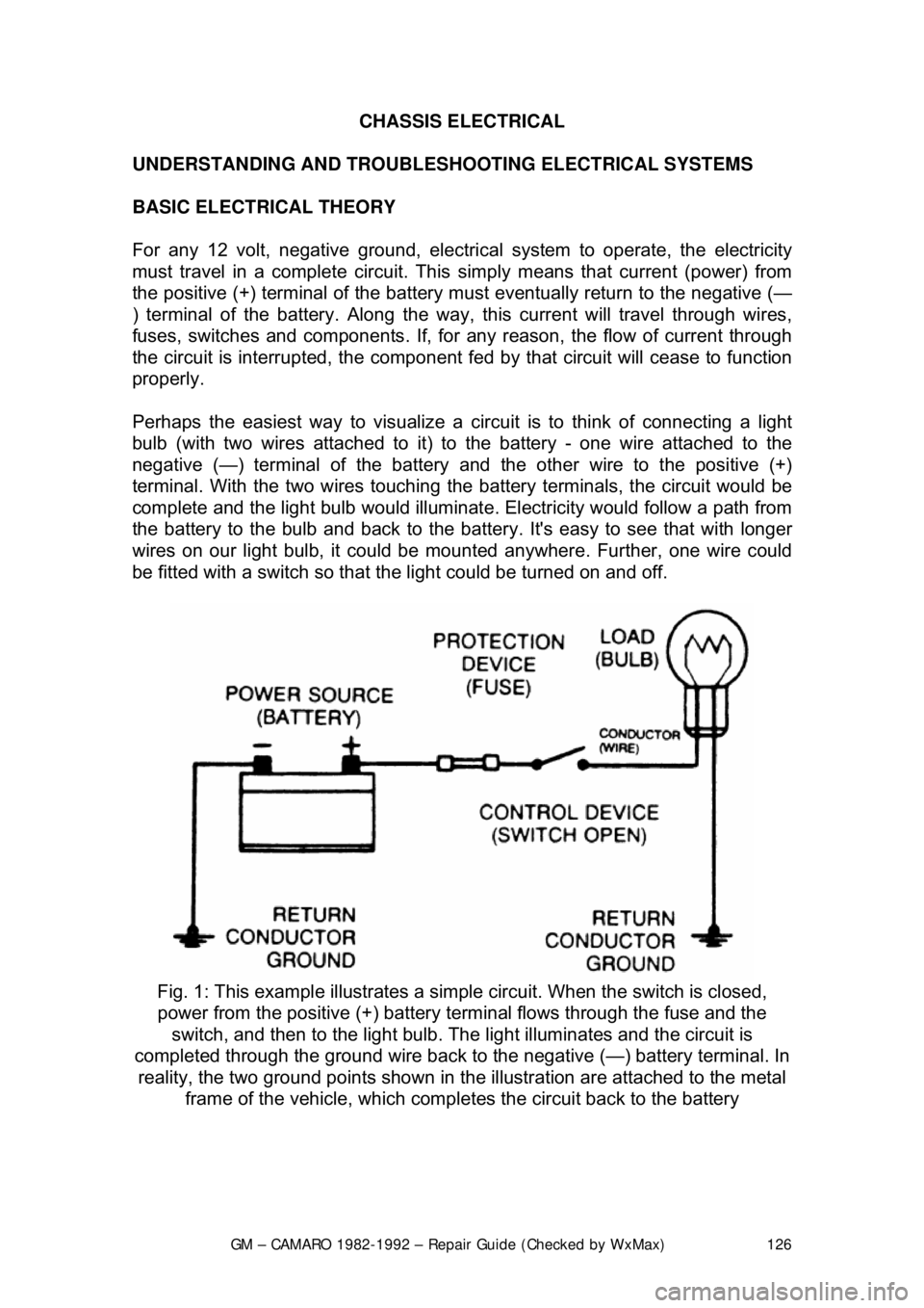
Perhaps the easiest way to visualize a circ uit is to think of connecting a light
bulb (with two wires attac hed to it) to the battery - one wire attached to the
negative (—) terminal of the battery and the other wire to the positive (+)
terminal. With the two wires touching the battery terminals, the circuit would be
complete and the light bulb would illuminat e. Electricity would follow a path from
the battery to the bulb and back to the bat tery. It's easy to see that with longer
wires on our light bulb, it could be mounted anywhere. Further, one wire could
be fitted with a switch so that t he light could be turned on and off.
Fig. 1: This example illu strates a simple circuit. Wh en the switch is closed,
power from the positive (+) battery te rminal flows through the fuse and the
switch, and then to the light bulb. The light illuminates and the circuit is
completed through the ground wire back to the negative (—) battery terminal. In
reality, the two ground point s shown in the illustration are attached to the metal
frame of the vehicle, which comple tes the circuit back to the battery
Page 129 of 875

GM – CAMARO 1982-1992 – Repair Guide (Checked by WxMax) 129
THE BATTERY
In most modern vehicles, the battery is
a lead/acid electrochemical device
consisting of six 2 volt subs ections (cells) connected in se ries, so that the unit is
capable of producing approximately 12 volt s of electrical pressure. Each
subsection consists of a series of positive and negative plates held a short
distance apart in a solution of sulfuric acid and water.
The two types of plates are of dissim ilar metals. This sets up a chemical
reaction, and it is this r eaction which produces current flow from the battery
when its positive and negative terminals are connected to an electrical \
load .
The power removed from the battery is r eplaced by the alternator, restoring the
battery to its original chemical state.
THE ALTERNATOR
On some vehicles there isn't an alter nator, but a generator. The difference is
that an alternator supplies alternating current which is then changed to direct
current for use on the vehicle, while a generator produces direct current.
Alternators tend to be more efficient and that is why they are used.
Alternators and generators are devices t hat consist of coils of wires wound
together making big electrom agnets. One group of coils spins within another set
and the interaction of the magnetic fields causes a current to flow. This current
is then drawn off the coils and fed into the vehicles electrical system.
GROUND
Two types of grounds are used in automot ive electric circuits. Direct ground
components are grounded to the frame thr ough their mounting points. All other
components use some sort of ground wire which is attached to the frame or
chassis of the vehicle. The electrical current runs through the chassis of the
vehicle and returns to the battery thr ough the ground (—) cable; if you look,
you'll see that the battery ground cabl e connects between the battery and the
frame or chassis of the vehicle.
It should be noted that a good percentage of electrical problems can be traced
to bad grounds.
PROTECTIVE DEVICES
It is possible for large surges of current to pass through the electrical system of
your vehicle. If this surge of current we re to reach the load in the circuit, the
surge could burn it out or severely dam age it. It can also overload the wiring,
causing the harness to get hot and melt t he insulation. To prevent this, fuses,
circuit breakers and/or fusible links are connected into the supply wires of the
electrical system. These items are nothing more than a built-in weak spot in the
system. When an abnormal amount of curr ent flows through the system, these
protective devices work as fo llows to protect the circuit:
Page 131 of 875

GM – CAMARO 1982-1992 – Repair Guide (Checked by WxMax) 131
•
Circuit Breaker - a circuit breaker is basically a self-repairing fuse. It will
open the circuit in the same fashio n as a fuse, but when the surge
subsides, the circuit breaker can be reset and does not need
replacement.
• Fusible Link - a fusible link (fuse link or main link) is a short length of
special, high temperatur e insulated wire that acts as a fuse. When an
excessive electrical current passes th rough a fusible link, the thin gauge
wire inside the link melt s, creating an intentional open to protect the
circuit. To repair the circuit, the link must be replaced. Some newer type
fusible links are housed in plug-in modules, which are simply replaced
like a fuse, while older type fusible lin ks must be cut and spliced if they
melt. Since this link is very early in the electrical path, it's the first place to
look if nothing on the vehicle works, yet the battery seems to be charged
and is properly connected.
CAUTION - Always replace fuses, circ uit breakers and fusible links with
identically rated component s. Under no circumstances should a component of
higher or lower amperage rating be substituted.
SWITCHES & RELAYS
Switches are used in electrical circuits to control the passage of current. The
most common use is to open and close circuits between the battery and the
various electric devices in the system. Switches are rated according to the
amount of amperage they c an handle. If a sufficient amperage rated switch is
not used in a circuit, the switch could overload and cause damage.
Fig. 2: The underhood fuse and relay panel usually contains fuses, relays,
flashers and fusible links
Page 138 of 875

GM – CAMARO 1982-1992 – Repair Guide (Checked by WxMax) 138
the ground side of the circuit) and
connect the positive lead to the
positive (+) side of the circuit (to t he power source or the nearest power
source). Note that the negative voltme ter lead will always be black and
that the positive voltmeter will alwa ys be some color other than black
(usually red).
• Ohmmeter - the ohmmeter is designed to read resistance (measured in
ohms) in a circuit or component. Mo st ohmmeters will have a selector
switch which permits the measurement of different ranges of resistance
(usually the selector swit ch allows the multiplication of the meter reading
by 10, 100, 1,000 and 10,000). Some ohmmeters are "auto-ranging"
which means the meter itself will dete rmine which scale to use. Since the
meters are powered by an internal battery, the ohmmeter can be used
like a self-powered test light. When the ohmmeter is connected, current
from the ohmmeter flows through the ci rcuit or component being tested.
Since the ohmmeter's internal resi stance and voltage are known values,
the amount of current flow throug h the meter depends on the resistance
of the circuit or component being test ed. The ohmmeter can also be used
to perform a continuity test for suspected open circuits. In using the
meter for making continuity checks, do not be concerned with the actual
resistance readings. Zero resistance, or any ohm reading, indicates
continuity in the circui t. Infinite resistance indi cates an opening in the
circuit. A high resistance reading w here there should be none indicates a
problem in the circuit. Checks for s hort circuits are made in the same
manner as checks for open circuits, ex cept that the circuit must be
isolated from both power and normal gr ound. Infinite resistance indicates
no continuity, while zero resi stance indicates a dead short.
WARNING - Never use an ohmmeter to check the resistance of a component or
wire while there is volt age applied to the circuit
• Ammeter - an ammeter measures the am ount of current flowing through
a circuit in units called amperes or amps. At normal operating voltage,
most circuits have a characteristic amount of amperes, called "current
draw" which can be measured usi ng an ammeter. By referring to a
specified current draw rating, then measuring the amperes and
comparing the two values, one can det ermine what is happening within
the circuit to aid in diagnosis. An open circuit, for example, will not allow
any current to flow, so the amme ter reading will be zero. A damaged
component or circuit will have an incr eased current draw, so the reading
will be high. The ammeter is always connected in series with the circuit\
being tested. All of the current that normally flows through the circuit
must also flow through the ammeter; if there is any other path for the
current to follow, the ammeter readi ng will not be accurate. The ammeter
itself has very little resistance to curr ent flow and, therefore, will not affect
the circuit, but it will measure current draw only when the circuit is closed
and electricity is flowing. Excessive current draw can blow fuses and
drain the battery, while a reduced current draw can cause motors to run \
slowly, lights to dim and other components to not operate properly.
Page 219 of 875
GM – CAMARO 1982-1992 – Repair Guide (Checked by WxMax) 219
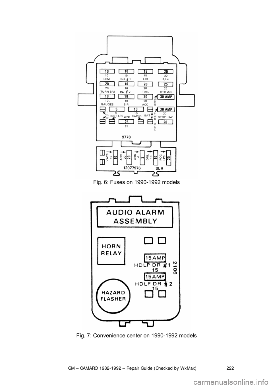
FUSE BLOCK
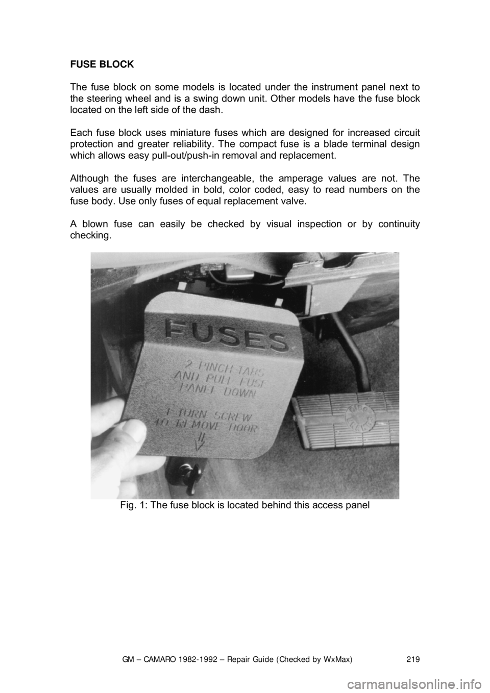
The fuse block on some models is loca
ted under the instrument panel next to
the steering wheel an d is a swing down unit. Other models have the fuse block
located on the left side of the dash.
Each fuse block uses miniature fuse s which are designed for increased circuit
protection and greater reliabi lity. The compact fuse is a blade terminal design
which allows easy pull-out/push- in removal and replacement.
Although the fuses are interchangeable , the amperage values are not. The
values are usually molded in bold, color coded, easy to read numbers on the
fuse body. Use only fuses of equal replacement valve.
A blown fuse can easily be checked by visual inspection or by continuity
checking.
Fig. 1: The fuse block is located behind this access panel
Page 220 of 875
GM – CAMARO 1982-1992 – Repair Guide (Checked by WxMax) 220
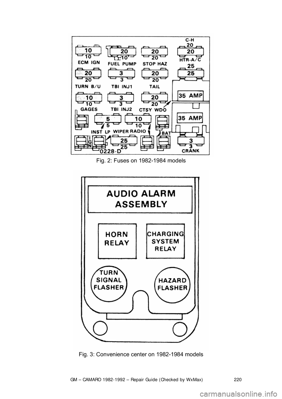
Fig. 2: Fuses on 1982-1984 models
Fig. 3: Convenience center on 1982-1984 models
Page 221 of 875
GM – CAMARO 1982-1992 – Repair Guide (Checked by WxMax) 221
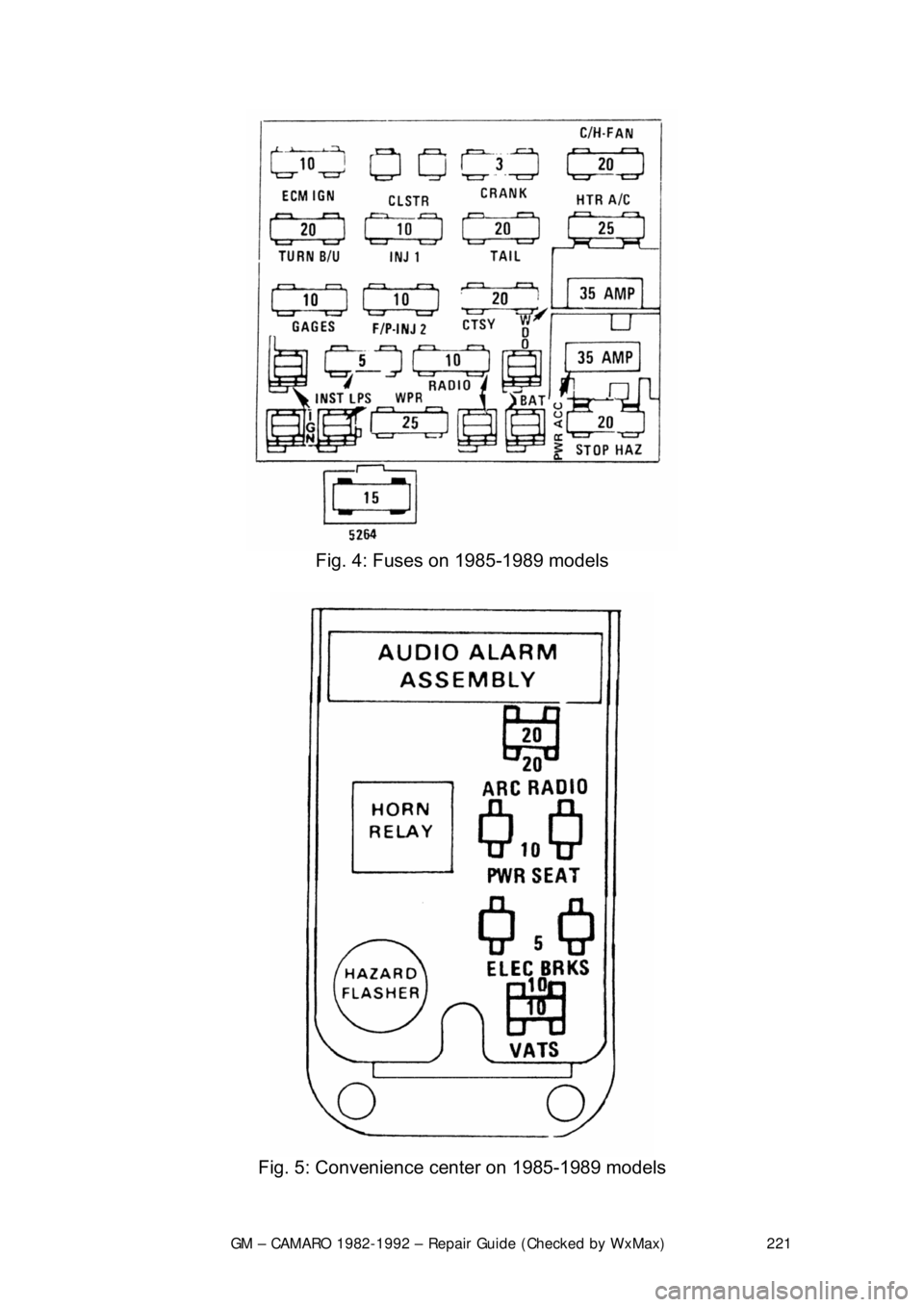
Fig. 4: Fuses on 1985-1989 models
Fig. 5: Convenience center on 1985-1989 models
Page 222 of 875
GM – CAMARO 1982-1992 – Repair Guide (Checked by WxMax) 222
Fig. 6: Fuses on 1990-1992 models
Fig. 7: Convenience center on 1990-1992 models