1982 CHEVROLET CAMARO steering wheel adjustment
[x] Cancel search: steering wheel adjustmentPage 91 of 875

GM – CAMARO 1982-1992 – Repair Guide (Checked by WxMax) 91
Avoid inhaling any dust from
any brake surface! When cleaning brake surfaces,
use a commercially available brake cleaning fluid.
1. Remove the caliper by following instru ctions of caliper removal procedure.
2. Remove dust cap, cotter pin, castle nut, thrust washer and outside wheel
bearing. Pull the disc/hub assembly from the steering knuckle.
To install:
3. Position the disc/hub assembly to t he spindle/steering knuckle. Install the
outside wheel bearing, thru st washer and castle nut. Tighten the castle nut
until the bearing is s nug. Back off the nut
1/4 turn. Refer to Suspension &
Steering for details on wheel bearing remo val, installation, and adjustment.
Install a new cotter pin and dust cap.
4. Install the brake caliper.
INSPECTION
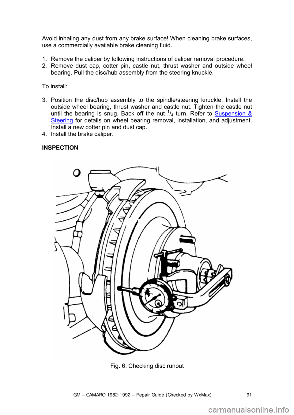
Fig. 6: Checking disc runout
Page 802 of 875

GM – CAMARO 1982-1992 – Repair Guide (Checked by WxMax) 802
BODY LUBRICATION
HOOD LATCH AND HINGES
Clean the latch surfaces and
apply clean engine oil to the latch pilot bolts and
the spring anchor. Use the engine oil to l ubricate the hood hinges as well. Use a
chassis grease to lubricate all the pivot points in the latch release mechanism.
DOOR HINGES
The gas tank filler door, car door, and rear hatch or trunk lid hinges should be
wiped clean and lubricated with clean engi ne oil. Silicone spray also works well
on seals, but must be applied more often. Use engine oil to lubricate the trunk
or hatch lock mechanism and the lock bo lt and striker. The door lock cylinders
can be lubricated easily with a shot of silicone spray or one of the many dry
penetrating lubricants commercially available.
PARKING BRAKE LINKAGE
Use chassis grease on the parking brake c able where it contacts the guides,
links, levers, and pulleys. The grease s hould be water resistant for durability.
ACCELERATOR LINKAGE
Lubricate the throttle lever, and the accele rator pedal lever at the support inside
the car with clean engine oil.
TRANSMISSION SHIFT LINKAGE
Lubricate the shift linkage with water re sistant chassis grease which meets GM
Specification 6031M or its equal.
FRONT WHEEL BEARINGS
Once every 30,000 miles, clean and repack wheel bearings with a wheel
bearing packer. Remove any excess grea se from the exposed surface of the
hub and seal.
REMOVAL, REPACKING, INSTA LLATION AND ADJUSTMENT
WARNING - It is important that wheel b earings be properly adjusted after
installation. Improperly adj usted wheel bearings can c ause steering instability,
front end shimmy and wander, and increased tire wear.
1. Raise the car and support it at the lower arm. Remove the tire and wheel
assembly.
2. Remove the brake caliper and support it on a wire.
3. Remove the dust cap, cotter pin, ca stle nut, thrust washer and outside
wheel bearing.
4. Pull the disc/hub assembly from the steering knuckle.
Page 833 of 875

GM – CAMARO 1982-1992 – Repair Guide (Checked by WxMax) 833
1. Siphon some brake fluid from the ma
ster cylinder. Raise and support the
vehicle.
2. Remove the wheel and tire. Remo ve the brake hose from the strut.
3. Remove the caliper and support on a wire. Refer to Brakes for
procedures, then remove the hub-and-disc.
4. Remove the splash shield. Disc onnect the tie rod from the steering
knuckle.
5. Support the lower control arm and disconnect the ball joint from the
steering knuckle using tool J-24292A.
6. Remove the 2 bolts securing the stru t to the steering knuckle and remove
the steering knuckle.
To install: 7. Place the steering knu ckle into position and install the 2 bolts securing
the strut to the st eering knuckle.
8. Support the lower control arm and c onnect the ball joint to the steering
knuckle.
9. Connect the tie rod to the steering knuckle. Install the splash shield.
10. Install the caliper.
11. Install the brake hose from the strut. Install the wheel and tire.
12. Lower the vehicle and refill the master cylinder with brake fluid.
FRONT WHEEL BEARINGS
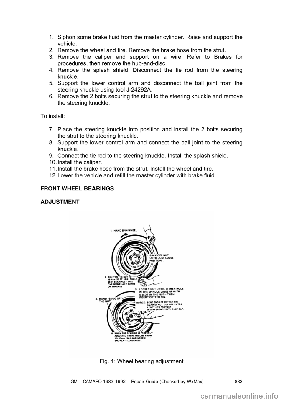
ADJUSTMENT
Fig. 1: Wheel bearing adjustment
Page 837 of 875

GM – CAMARO 1982-1992 – Repair Guide (Checked by WxMax) 837
1. Loosen the clamp bolts at each end
of the steering tie rod adjustable
sleeves.
2. With the steering wheel set strai ght ahead, turn the adjusting sleeves to
obtain the proper adjustment.
3. When the adjustment has been completed, check to see that the number
of threads showing on each end of the sleeve are equal. Also check that
tie rod end housings are at the right angles to the steering arm.
Page 847 of 875

GM – CAMARO 1982-1992 – Repair Guide (Checked by WxMax) 847
DISARMING
1. Turn the steering wheel to align the w heels in the straight-ahead position.
2. Turn the ignition switch to the LOCK position.
3. Remove the SIR air bag fuse from the fuse block.
4. Remove the left side trim panel and disconnect the yellow 2-way SIR
harness wire connector at the bas e of the steering column.
To enable system: 5. Turn the ignition switch to the LOCK position.
6. Reconnect the yello w 2-way connector at the base of the steering
column.
7. Reinstall the SIR fuse and the left side trim panel.
8. Turn the ignition switch to the RUN position.
9. Verify the SIR indicator light flashes 7-9 times, if not as specified, inspect
system for malfunction or c ontact the manufacturer.
For more details on the SIR system - including disarming instructions for
passenger bags - please refer to Chassis Electrical in this repair guide.
SUPPLEMENTAL INFLATABLE REST RAINT (SIR) COIL ASSEMBLY
After performing repairs on the inter nals of the steering column the coil
assembly must be centered in order to avoid damaging the coil or accidental
deployment of the air bag. There are 2 different styles of coils, one rotates
clockwise and the other rotates counterclockwise.
ADJUSTMENT (CENTERING THE COIL) 1. With the system properly disarmed, hold the coil assembly with the clear
bottom up to see the coil ribbon.
2. While holding the coil assembly, depr ess the lock spring and rotate the
hub in the direction of the arrow until it stops. The coil should now be
wound up snug against the center hub.
3. Rotate the coil assembly in the opposite direction approximately 2
1/2
turns and release the lock spring between the locking tabs in front of the
arrow.
4. Install the coil assembly onto the steering shaft.
STEERING WHEEL
WARNING - Before attempting any repairs involving the steering wheel or
disassembly of it, ensure that the Supple mental Inflatable Restraint (Air Bag)
system is properly disarmed.
REMOVAL & INSTALLATION
If the vehicle is equipped with a SIR (A ir Bag) system, ensure that the proper
disarming procedure is followed.
Page 853 of 875

GM – CAMARO 1982-1992 – Repair Guide (Checked by WxMax) 853
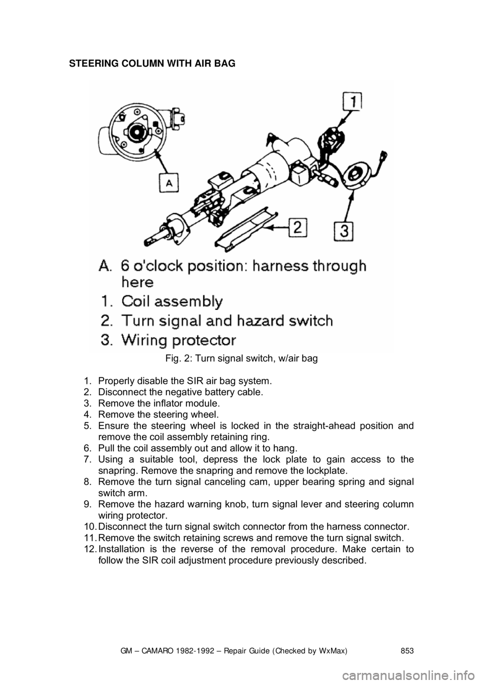
STEERING COLUMN WITH AIR BAG
Fig. 2: Turn signal switch, w/air bag
1. Properly disable the SIR air bag system.
2. Disconnect the negative battery cable.
3. Remove the inflator module.
4. Remove the steering wheel.
5. Ensure the steering wheel is locked in the straight-ahead position and
remove the coil assembly retaining ring.
6. Pull the coil assembly out and allow it to hang.
7. Using a suitable tool, depress the lock plate to gain access to the
snapring. Remove the snapring and remove the lockplate.
8. Remove the turn signal cancelin g cam, upper bearing spring and signal
switch arm.
9. Remove the hazard warning knob, tu rn signal lever and steering column
wiring protector.
10. Disconnect the turn signal switch connector from the harness connector.
11. Remove the switch retaining screws and remove the turn signal switch.
12. Installation is the reverse of t he removal procedure. Make certain to
follow the SIR coil adjustment pr ocedure previously described.
Page 857 of 875

GM – CAMARO 1982-1992 – Repair Guide (Checked by WxMax) 857
6. Remove the bolts attaching the toe plate to the cowl.
7. Disconnect the electrical connectors.
8. Remove the capsule nuts attachi
ng the steering column support bracket
to the instrument panel.
9. Disconnect the park lock cable from the ignition switch inhibitor, if
equipped with automatic transmission.
10. Remove the steering column from the vehicle.
To install:
If a replacement steering column is bein g installed, do not remove the anti-
rotation pin until after the steering co lumn has been connected to the steering
gear. Removing the anti-rotation pin before the steering column is connected to
the steering gear may dam age the SIR coil assembly.
11. Position the steering column in the vehicle.
12. Connect the park lock cable to the ig nition switch inhibitor on vehicles
with automatic transmission.
13. Install the capsule nuts attaching the steering column support bracket to
the instrument panel and tighten to 20 ft. lbs. (27 Nm).
14. Install the nut and bolt to the upper intermediate shaft coupling attaching
the upper intermediate shaft to the steer ing column. Tighten the nut to 44
ft. lbs. (60 Nm).
15. Install the bolts attaching the toe pl ate to the cowl and tighten to 58 inch
lbs. (6.5 Nm).
16. Connect the electrical connectors.
17. Remove the anti-rotation pin if a se rvice replacement steering column is
being installed.
18. Install the knee bolster and bracket, if equipped.
19. Install the sound insulator panel.
If SIR coil has become uncentered by turni ng of the steering wheel without the
column connected to the st eering gear, follow the proper adjustment procedure
for the SIR coil assembly before proceeding.
20. Install the steering wheel.
21. Connect the negative battery cable.
22. Enable the SIR system as follows: a. Connect the yellow 2-way SIR harness connector to the base of
the steering column and CPA clip and install the SIR fuse.
b. Install the left sound insulator.
c. Turn the ignition switch to the RUN position and verify that the
inflatable restraint indicator fl ashes 7-9 times and then turns OFF.
If the indicator does not respond as stated, a problem within the
SIR system is indicated.