1982 CHEVROLET CAMARO belt drive
[x] Cancel search: belt drivePage 28 of 875

GM – CAMARO 1982-1992 – Repair Guide (Checked by WxMax) 28
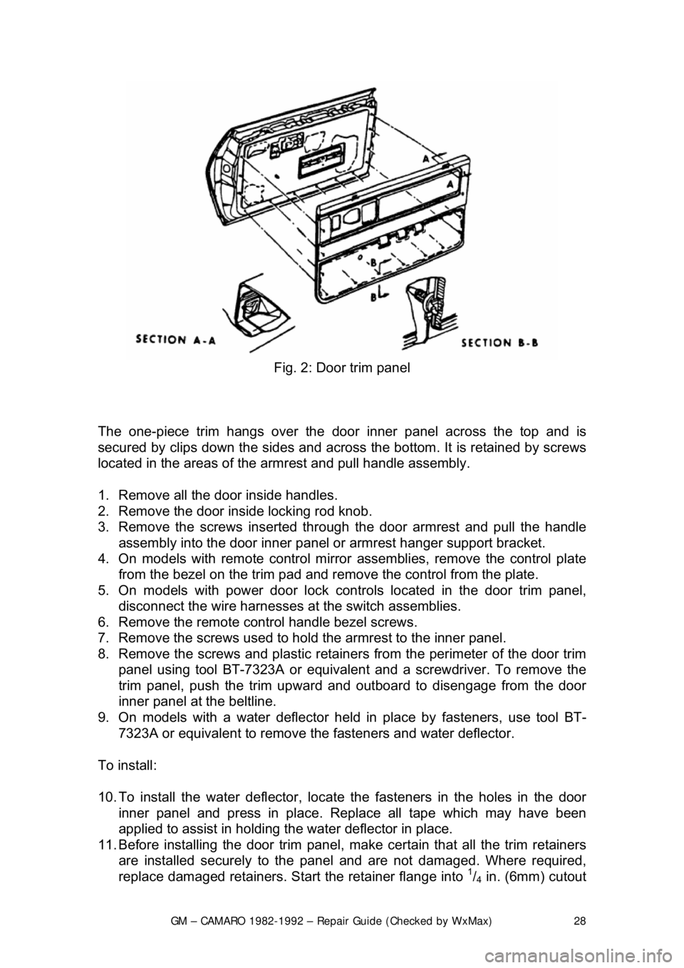
Fig. 2: Door trim panel
The one-piece trim hangs over the door inner panel across the top and is
secured by clips down the sides and across the bottom. It is retained by screws
located in the areas of the armrest and pull handle assembly.
1. Remove all the door inside handles.
2. Remove the door inside locking rod knob.
3. Remove the screws inserted through the door armrest and pull the handle
assembly into the door inner panel or armrest hanger support bracket.
4. On models with remote control mirror assemblies, remove the control plate
from the bezel on the trim pad and remo ve the control from the plate.
5. On models with power door lock contro ls located in the door trim panel,
disconnect the wire harnesses at the switch assemblies.
6. Remove the remote control handle bezel screws.
7. Remove the screws used to hold the armrest to the inner panel.
8. Remove the screws and plastic retainer s from the perimeter of the door trim
panel using tool BT-7323A or equivalent and a screwdriver. To remove the
trim panel, push the trim upward and out board to disengage from the door
inner panel at the beltline.
9. On models with a water deflector held in place by fasteners, use tool BT-
7323A or equivalent to remove th e fasteners and water deflector.
To install:
10. To install the water deflector, locate the fasteners in the holes in the door
inner panel and press in place. R eplace all tape which may have been
applied to assist in holding t he water deflector in place.
11. Before installing the door trim panel, make certain that all the trim retainers
are installed securely to the panel and are not damaged. Where required,
replace damaged retainers. St art the retainer flange into
1/4 in. (6mm) cutout
Page 45 of 875

GM – CAMARO 1982-1992 – Repair Guide (Checked by WxMax) 45
Fig. 5: Seat belt attachment
1. Remove the cover from the anchor plate.
2. Remove the attaching bolt, anchor pl ate and washer from the door pillar.
3. Remove the bolt cover from the rear of the retractor assembly.
4. Remove the bolt retaining the retrac tor to the floor panel and remove the
retractor.
5. Remove the buckle assemb ly from the floor panel.
6. Remove the cap which conceals t he buckle assembly bolt and remove the
bolt.
7. Remove the seat belt warning wire from the drivers side buckle and remove
the buckle assembly from the vehicle.
8. Installation is the reverse of removal. Tighten all bolts to 31 ft. lbs. (43 Nm).
POWER SEAT MOTOR
REMOVAL & INSTALLATION
1. Remove the front seat assemb ly and place upside down on a clean
protected surface.
2. Disconnect the motor feed wires from the motors.
3. Remove the nut securing the front of the motor support bracket to the
inboard adjuster and withdraw the asse mbly from the adjuster and the
gearnut drives.
4. Disconnect the drive cables from t he motors and complete removal of the
support bracket with the motor attached.
Page 351 of 875

GM – CAMARO 1982-1992 – Repair Guide (Checked by WxMax) 351
alternating current developed
within the stator windings to a direct (DC) current
at the output (BAT) terminal. Three of these diodes are negative and are
mounted flush with the end frame while t he other three are positive and are
mounted into a strip called a heat sink. The positive diodes are easily identified
as the ones within small cavities or depressions.
The alternator charging system is a negative (-) ground system which consists
of an alternator, a regulat or, a charge indicator, a storage battery and wiring
connecting the components, and fuse link wire.
The alternator is belt-driven from t he engine. Energy is supplied from the
alternator/regulator system to the rotati ng field through two brushes to two slip-
rings. The slip-rings are mounted on the rotor shaft and are connected t\
o the
field coil. This energy supplied to the ro tating field from the battery is called
excitation current and is used to init ially energize the field to begin the
generation of electricity. Once the alter nator starts to generate electricity, the
excitation current comes from its ow n output rather than the battery.
The alternator produces power in the form of alternating current. The alternating
current is rectified by 6 diodes into dire ct current. The direct current is used to
charge the battery and power the rest of the electrical system.
When the ignition key is turned ON, current flows from the battery, through the
charging system indicator light on the in strument panel, to the voltage regulator,
and to the alternator. Since the alternat or is not producing any current, the
alternator warning light comes on. When the engine is started, the alternator
begins to produce current and turns the alte rnator light off. As the alternator
turns and produces current, the current is divided in two ways: part to the
battery(to charge the battery and power the electrical components of the
vehicle), and part is returned to the alte rnator (to enable it to increase its
output). In this situation, the alternator is receiving current from the battery and
from itself. A voltage regulat or is wired into the current supply to the alternator
to prevent it from receiving too much cu rrent which would cause it to put out too
much current. Conversely, if the voltage regulator does not allow the alternator
to receive enough current, the battery will not be fully charged and will
eventually go dead.
The battery is connected to the alternator at all times, whether the ignition key is
turned ON or not. If the battery were shorted to ground, the alternator would
also be shorted. This woul d damage the alternator. To prevent this, a fuse link
is installed in the wiring between the battery and the alternator. If the battery is
shorted, the fuse link melts, protecting the alternator.
An alternator is better that a convent ional, DC shunt generator because it is
lighter and more compact, because it is designed to supply the battery and
accessory circuits through a wide range of engine speeds, and because it
eliminates the necessary maintenance of replacing brushes and servicing
commutators.
PRECAUTIONS
Page 354 of 875

GM – CAMARO 1982-1992 – Repair Guide (Checked by WxMax) 354
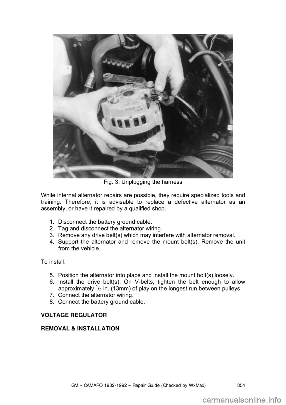
Fig. 3: Unplugging the harness
While internal alternator repairs are possi ble, they require specialized tools and
training. Therefore, it is advisable to replace a defective alternator as an
assembly, or have it repai red by a qualified shop.
1. Disconnect the battery ground cable.
2. Tag and disconnect the alternator wiring.
3. Remove any drive belt(s) which may interfere with alternator removal.
4. Support the alternator and remove the mount bolt(s). Remove the unit
from the vehicle.
To install: 5. Position the alternator into place and install the mount bolt(s) loosely.
6. Install the drive belt(s). On V- belts, tighten the belt enough to allow
approximately
1/2 in. (13mm) of play on the longest run between pulleys.
7. Connect the alternator wiring.
8. Connect the battery ground cable.
VOLTAGE REGULATOR
REMOVAL & INSTALLATION
Page 363 of 875

GM – CAMARO 1982-1992 – Repair Guide (Checked by WxMax) 363
2.5L ENGINE
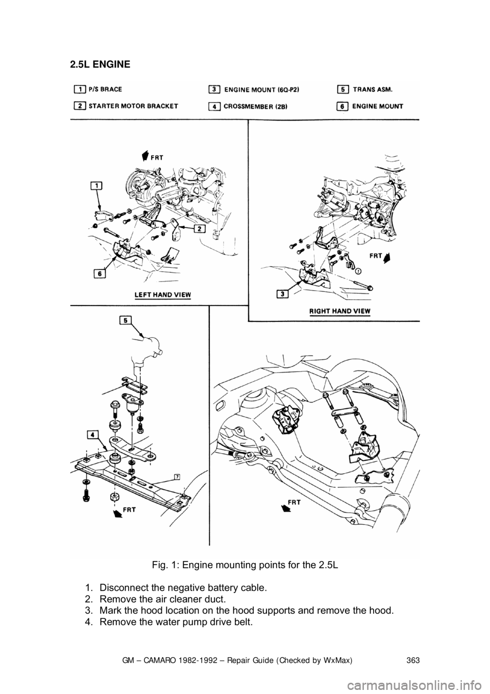
Fig. 1: Engine mountin g points for the 2.5L
1. Disconnect the negative battery cable.
2. Remove the air cleaner duct.
3. Mark the hood location on the hood supports and remove the hood.
4. Remove the water pump drive belt.
Page 365 of 875

GM – CAMARO 1982-1992 – Repair Guide (Checked by WxMax) 365
31. Connect the bulkhead harness connec
tor, wires and hoses. Reroute the
ECM harness in its original location. Install the hush panel and fenderwell
splash panel.
32. Install the radiator, fan and fan sh roud. Connect the radiator and heater
hoses, along with the transmission cooler lines.
33. Connect the vacuum brake booster li ne, the throttle linkage and cruise
control cable. Install the distributor cap.
34. Fill the cooling system with the proper type and amount of coolant and
the crankcase with the proper type of oil to the correct level.
35. Install the water pump drive bel t, the air cleaner duct and the hood.
36. Connect the negative battery cable, st art the engine and check for leaks.
2.8L AND 3.1L ENGINES
Fig. 2: Engine mountin g points for the V6
1. Disconnect the negative battery cable.
2. Remove the air cleaner duct.
3. Mark the hood location on the hood supports and remove the hood.
4. Remove the water pump drive belt.
5. Drain the radiator and remove t he radiator hoses. Disconnect the heater
hoses and the transmission cooler lines.
6. Remove the fan shroud, fan and radiator.
7. Disconnect the throttle linkage, includi ng the cruise control detent cable.
Page 367 of 875

GM – CAMARO 1982-1992 – Repair Guide (Checked by WxMax) 367
5.0L AND 5.7L ENGINES
Fig. 3: Engine mountin g points for the V8
1. Disconnect the negative battery cable.
2. Mark the location of the hood on the hood hinges and remove the hood.
3. Remove the air cleaner.
4. Drain the cooling system.
5. Remove the radiator hoses.
6. Disconnect the transmission cooler li nes, the electrical connectors and
retaining clips at the fan and remove the fan and shroud.
7. Remove the radiator.
8. Remove the accessory drive belt.
9. Disconnect the throttle cable.
10. Remove the plenum extension scr ews and the plenum extension, if
equipped.
11. Disconnect the spark plug wires at the distributor and remove the
distributor.
12. Disconnect the necessary vacuum hoses and wiring.
13. Disconnect the power steering and air conditioning compressors from
their respective brackets and lay them aside.
14. Properly relieve the fuel system pressure. Disconnect the fuel lines.
15. Disconnect the negative battery cable at the engine block.
16. Raise and safely support the vehicle.
17. Remove the exhaust pipes at the exhaust manifolds.
18. Remove the flywheel cover and remove the converter to flywheel bolts.
19. Disconnect the starter wires.
20. Remove the bellhousing bolts and the motor mount through-bolts.
21. Lower the vehicle.
22. Support the transmission with a suitable jack.
Page 370 of 875

GM – CAMARO 1982-1992 – Repair Guide (Checked by WxMax) 370
2.8L AND 3.1L ENGINES
Fig. 2: Valve cover removal for the V6
1. Disconnect the negative battery cable.
2. For the left side valve cove r removal, proceed as follows:
a. Remove the accessory drive belt.
b. Remove the transmission dipstick, if required.
c. Remove the air management hose and air conditioning bracket, if
equipped.
d. Remove the intake plenum and throttle body assembly, on fuel
injected engines.
e. Remove the valve cover reinforcements and nuts.
3. For the right side valve cover removal, proceed as follows:
a. Remove the EGR valve adapter with the EGR valve and shield
from the exhaust manifold.
b. Remove the coil and coil mounting bracket from the cylinder head.
c. Disconnect the crankcase vent pipe.
d. Remove the intake plenum and throttle body assembly.
e. Remove the valve cover reinforcements and nuts.
4. Remove cover. If cover adheres to cylinder head, shear off by bumping end of rocker arm cover with palm of hand or rubber mallet. If cover still
will not come loose, CAREFULLY pry until loose. DO NOT DISTORT
THE SEALING FLANGE.
To install: 5. Clean the sealing surface on cylinder head and intake manifold of all old
RTV or gasket. Make sure no oil or ol d gasket is present when applying
new RTV or gasket.