1982 CHEVROLET CAMARO checking oil
[x] Cancel search: checking oilPage 362 of 875

GM – CAMARO 1982-1992 – Repair Guide (Checked by WxMax) 362
OIL PRESSURE SENDING UNIT
Replace the sending unit by disconnecting
the electrical connector and using a
special socket to remove it.
ENGINE
MECHANICAL ENGINE
REMOVAL & INSTALLATION
In the process of removing the engine, you will come across a number of steps
which call for the removal of a separ ate component or system, such as
"disconnect the exhaust system " or "remove the radiator." In most instances, a
detailed removal procedure can be found elsewhere in this repair guide.
It is virtually impossible to list each individual wire and hose which must be
disconnected, simply because so many different model and engine
combinations have been manufactured. Careful observation and common
sense are the best possible approaches to any repair procedure.
Removal and installation of the engine ca n be made easier if you follow these
basic points:
• If you have to drain any of the fl uids, use a suitable container.
• Always tag any wires or hoses and, if possible, the components they
came from before disconnecting them.
• Because there are so many bolts and fasteners involved, store and label
the retainers from com ponents separately in muffin pans, jars or coffee
cans. This will prevent conf usion during installation.
• After unbolting the transmission or trans axle, always make sure it is
properly supported.
• If it is necessary to disconnect t he air conditioning system, have this
service performed by a qualified tec hnician using a recovery/recycling
station. If the system does not have to be disconnected, unbolt the
compressor and set it aside.
• When unbolting the engine mounts, a lways make sure the engine is
properly supported. When removing t he engine, make sure that any
lifting devices are properly attached to the engine. It is recommended
that if your engine is supplied with lifting hooks, your lifting apparatus be
attached to them.
• Lift the engine from its compartment sl owly, checking that no hoses,
wires or other component s are still connected.
• After the engine is clear of the compar tment, place it on an engine stand
or workbench.
• After the engine has been removed, y ou can perform a partial or full
teardown of the engine using the procedur es outlined in this repair guide.
Page 436 of 875

GM – CAMARO 1982-1992 – Repair Guide (Checked by WxMax) 436
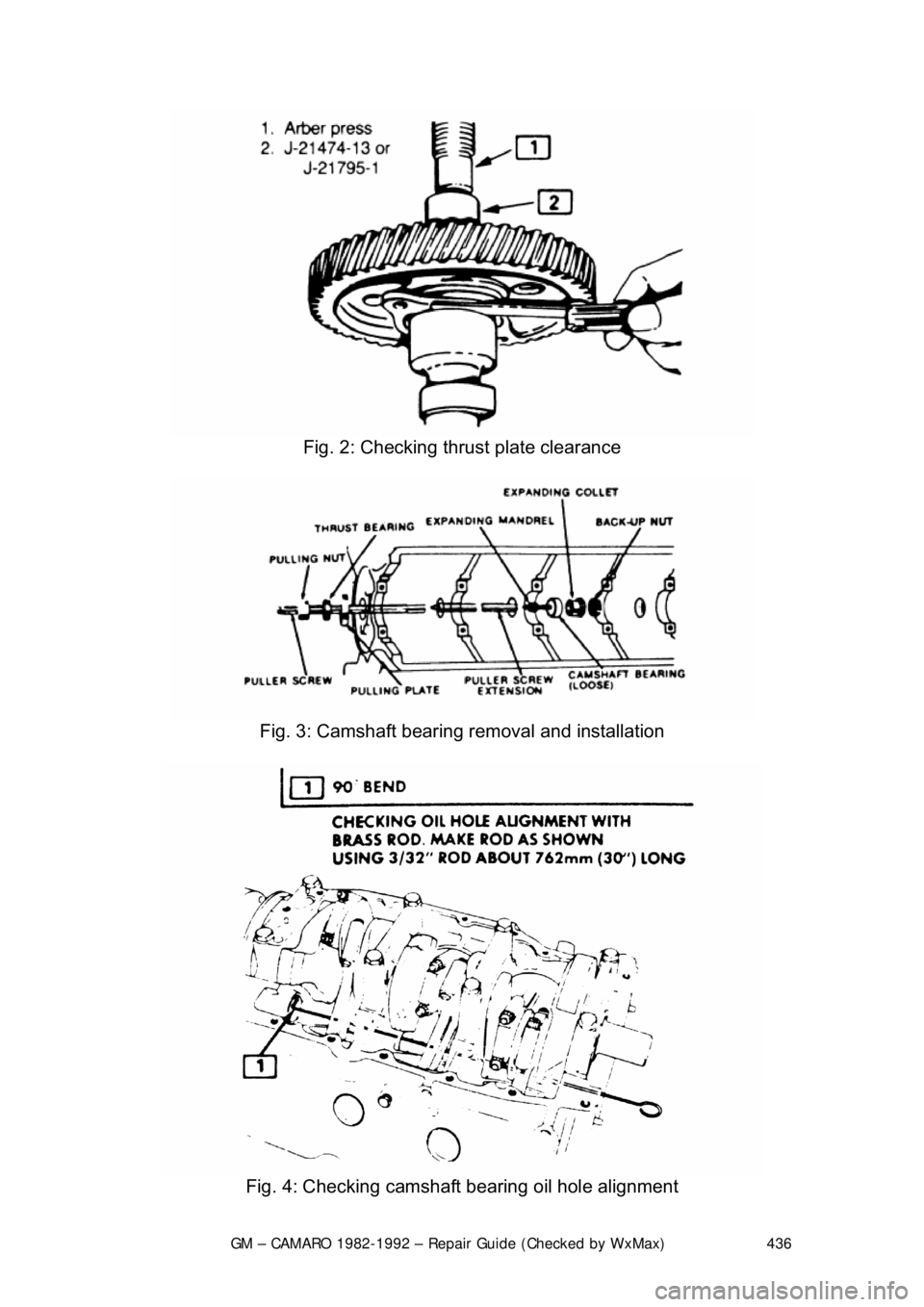
Fig. 2: Checking thrust plate clearance
Fig. 3: Camshaft bearing removal and installation
Fig. 4: Checking camshaft bearing oil hole alignment
Page 443 of 875

GM – CAMARO 1982-1992 – Repair Guide (Checked by WxMax) 443
Ensure that oil holes are properly al
igned. Replace camshaft rear plug, and
stake it into position to aid retention.
INSPECTION
CAMSHAFT LOBE LIFT
Check the lift of each lobe in consecutiv e order and make a note of the reading.
1. Remove the fresh air inlet tube a nd the air cleaner. Remove the heater
hose and crankcase ventilation hoses. Remove valve rocker arm
cover(s).
2. Remove the rocker arm stud nut or fulcrum bolts, fulcrum seat and rocker
arm.
3. Make sure the pushrod is in the valve tappet socket. Install a dial indicator so that the actuating poin t of the indicator is in the pushrod
socket (or the indicator ball socket adapter tool is on the end of the
pushrod) and in the same plane as the pushrod movement.
4. Disable the ignition and fuel systems.
5. Install a remote starter switch. Crank the engine with the ignition and fuel
system disabled. Turn the crankshaft ov er until the tappet is on the base
circle of the camshaft lobe. At this position, the pushrod will be in its
lowest position.
6. Zero the dial indicator. Continue to rotate the crankshaft slowly until the
pushrod is in the fully raised position.
7. Compare the total lift recorded on the dial indicator with the specification
shown on the Camshaft Specification chart.
To check the accuracy of the original in dicator reading, continue to rotate the
crankshaft until the indicator reads zero. If the lift on any lobe is below specified
wear limits listed, the ca mshaft and the valve tappet operating on the worn
lobe(s) must be replaced.
8. Install the rocker arm, fulcrum seat and stud nut or fulcrum bolts. Adjust
the valves, if required (r efer to the valves procedure in this section).
9. Install the valve rocker arm cover(s) and the air cleaner.
CAMSHAFT END PLAY
On all gasoline V8 engi nes, prying against the aluminum-nylon camshaft
sprocket, with the valve train load on t he camshaft, can break or damage the
sprocket. Therefore, the rocker arm adj usting nuts must be backed off, or the
rocker arm and shaft assembly must be loosened sufficiently to free the
camshaft. After checking the camshaft e nd play, check the valve clearance.
Adjust if required (refer to procedure in this section).
1. Push the camshaft toward the rear of the engine. Install a dial indicator or
equivalent so that the indicator point is on the camshaft sprocket
attaching screw.
Page 509 of 875

GM – CAMARO 1982-1992 – Repair Guide (Checked by WxMax) 509
1. Before installing the
piston/connecting rod assembly, oil the pistons,
piston rings and the cylinder walls with light engine oil. Install connecting
rod bolt protectors or rubber hose onto the connecting rod bolts/studs.
Also perform the following: a. Select the proper ring set for the size cylinder bore.
b. Position the ring in the bore in which it is going to be used.
c. Push the ring down into the bor e area where normal ring wear is
not encountered.
d. Use the head of the piston to posi tion the ring in the bore so that
the ring is square with the cyli nder wall. Use caution to avoid
damage to the ring or cylinder bore.
e. Measure the gap betw een the ends of the ring with a feeler gauge.
Ring gap in a worn cylinder is normally greater than specification.
If the ring gap is greater than the specified limits, try an oversize
ring set.
Fig. 13: Checking the piston ring-to-ri ng groove side clearance using the ring
and a feeler gauge
Page 763 of 875

GM – CAMARO 1982-1992 – Repair Guide (Checked by WxMax) 763
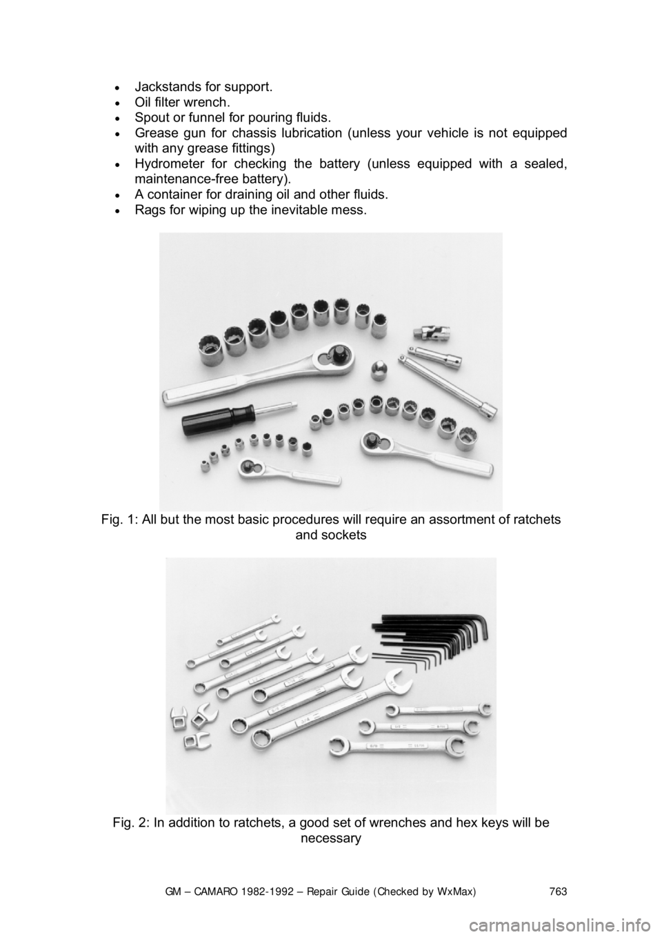
•
Jackstands for support.
• Oil filter wrench.
• Spout or funnel for pouring fluids.
• Grease gun for chassis lubrication (unl ess your vehicle is not equipped
with any grease fittings)
• Hydrometer for checking the battery (unless equipped with a sealed,
maintenance-free battery).
• A container for draining oil and other fluids.
• Rags for wiping up the inevitable mess.
Fig. 1: All but the most basic procedures will require an assortment of ratchets
and sockets
Fig. 2: In addition to ratchets, a good set of wrenches and hex keys will be
necessary
Page 778 of 875

GM – CAMARO 1982-1992 – Repair Guide (Checked by WxMax) 778
Fig. 4: Add clean oil to the engine to ac hieve the correct level, indicated on
dipstick. Do not overfill
Your engine oil should be checked at regular intervals (such as every fuel stop).
Check the engine oil as follows:
1. Make sure the car is parked on level ground.
2. When checking the oil le vel it is best for the engine to be at normal
operating temperature, although checking the oil immediately after
stopping will lead to a false reading. Wa it a few minutes after turning off
the engine to allow the oil to drain back into the crankcase.
3. Open the hood and locate the dipsti ck which should be on either the
passenger's side for the V8 engine or driver's side for the L4 and V6
engines. Pull the dipstick fr om its tube, wipe it clean and then reinsert it.
4. Pull the dipstick out agai n and, holding it horizontally, read the oil level.
The oil should be between the FULL and ADD marks on the dipstick. If
the oil is below the ADD mark, add oil of the prop er viscosity through the
capped opening in the top of the cylinder head cover.
5. Replace the dipstick and check the o il level again after adding any oil. Be
careful not to overfill the crankcase. Approximately 1 quart (0.9L) of oil
will raise the level from the ADD mark to the FULL mark. Excess oil will
generally be consumed at an accelerated rate.