Page 8 of 875
GM – CAMARO 1982-1992 – Repair Guide (Checked by WxMax) 8
REAR COMPARTMENT LIFT WINDOW
REMOVAL & INSTALLATION
Fig. 1: Rear hatch hinge
Page 9 of 875

GM – CAMARO 1982-1992 – Repair Guide (Checked by WxMax) 9
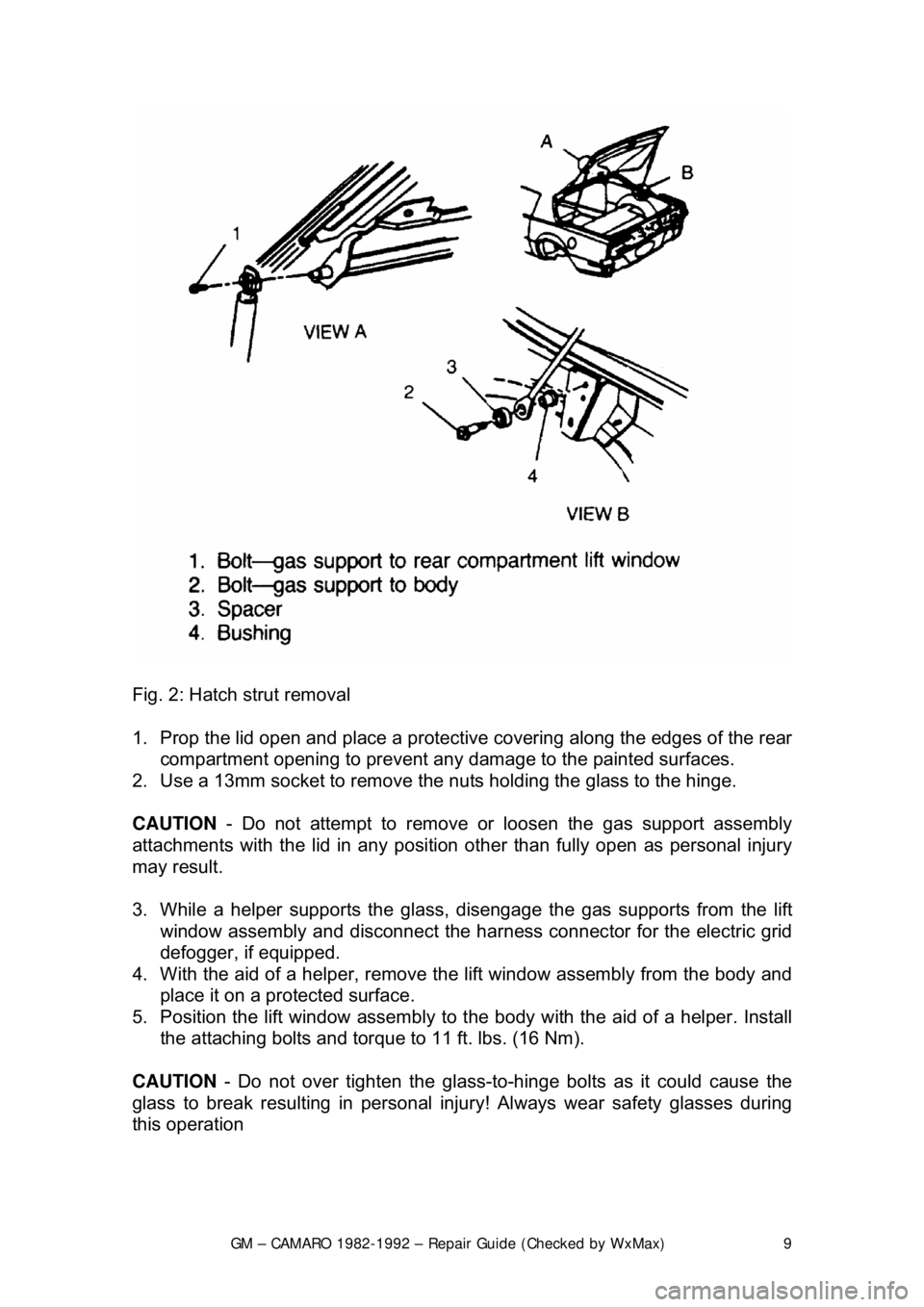
Fig. 2: Hatch strut removal
1. Prop the lid open and place a protective covering along the edges of the rear
compartment opening to prevent any damage to the painted surfaces.
2. Use a 13mm socket to remove the nuts holding the glass to the hinge.
CAUTION - Do not attempt to remove or loosen the gas support assembly
attachments with the lid in any position other than fully open as person\
al injury
may result.
3. While a helper supports the glass, disengage the gas supports from the lift
window assembly and disconnect the har ness connector for the electric grid
defogger, if equipped.
4. With the aid of a helper, remove the lift window assembly from the body and
place it on a protected surface.
5. Position the lift window assembly to t he body with the aid of a helper. Install
the attaching bolts and torque to 11 ft. lbs. (16 Nm).
CAUTION - Do not over tighten the glass-to -hinge bolts as it could cause the
glass to break resulting in personal injury! Always wear safety glasses during
this operation
Page 10 of 875
GM – CAMARO 1982-1992 – Repair Guide (Checked by WxMax) 10
6. Connect the harness connector for the el
ectric grid defogger, if equipped,
and connect the gas supports to the lift window assembly.
7. Lower the lid and check alignment.
ADJUSTMENT
The rear compartment lift window assembly height, fore and aft and side \
adjustments are controlled at the hinge-to-b ody location. This area of the body
has oversize hinge attaching holes in addition to the hinge-to-body spacers.
Adjustments at the hinge location mu st be made with the gas supports
disengaged. Additional height adjustment can also be made at the lower panel
by adjusting the rubber bumpers. Bolt s holding hinge-to-body should be
tightened to 15-20 ft. lbs. (20-28 Nm).
BUMPERS
REMOVAL & INSTALLATION
FRONT FASCIA
Fig. 1: Front bumper fascia
Page 29 of 875

GM – CAMARO 1982-1992 – Repair Guide (Checked by WxMax) 29
attachment hole in the trim panel, rotate the retainer until the flange is
engaged fully.
12. Connect all electrical components where present.
13. To install the door trim panel, locate the top of the assembly over the upper
flange of the door inner panel, inserting the door handle through the handle
slot in the panel and press down on the trim panel to engage the upper
retaining clips.
14. Position the trim panel to the door inner panel so the trim retainers are
aligned with the attaching holes in t he panel and tap the retainers into the
holes with the palm of hand or a clean rubber mallet.
15. Install the screws used to hold the armrest to the inner panel.
16. Install the remote control handle bezel screws.
17. On models with power door lock contro ls located in the door trim panel,
connect the wire harnesses at the switch assemblies.
18. On models with remote control mirror assemblies, install the control to the
plate. Install the control plate to the bezel on the trim pad.
19. Install the handle assemb ly and install the screws inserted through the door
armrest.
20. Install the door inside locking rod knob.
21. Install all the door inside handles.
HEADLINER
REMOVAL & INSTALLATION
Fig. 1: Headliner installation
1. Disconnect the negative battery cable.
2. Remove the dome lamp and sunshade.
3. Remove the coat hooks and seat bel t escutcheon, by unsnapping from the
headliner.
4. Remove the rear window opening molding.
Page 31 of 875
GM – CAMARO 1982-1992 – Repair Guide (Checked by WxMax) 31
Fig. 2: Door lock linkage
1. Raise the door window. Remove the door tr im panel and detach the inner
panel water deflector enough to expose the access hole.
2. Disengage the lock cylinder to t he lock rod at the cylinder.
CAUTION - If removing the lock cylinder reta iner by hand, wear gloves to
prevent personal injury.
3. With a screwdriver or similar tool, s lide the lock cylinder retainer forward until
it disengages. The retainer can also be removed by hand by grasping anti\
-
theft shield at the top of the retainer and rotating until disengaged. Remove
the lock cylinder from the door.
4. Lubricate the cylinder wit h the proper lubricant.
5. Position the cylinder into place and ro tate it until the cylinder engages. Install
the cylinder retainer.
6. Engage the lock cylinder to lock rod at the cylinder.
7. Install the inner panel wate r deflector and door trim panel.
Page 33 of 875
GM – CAMARO 1982-1992 – Repair Guide (Checked by WxMax) 33
Fig. 2: Door lock actuator
1. Disconnect the negative battery c able. Remove the door panel.
2. Raise the window fully. Disconnect t he electrical connector from the
actuator.
3. Drive the rivet cent er pins out using a
1/8 in. (3mm) punch and hammer, then
using a 1/4 in. (6mm) drill bit, remove the rivet head.
4. Remove the actuator rod and remove the door lock actuator.
5. Installation is the revers e of the removal procedure.
Page 34 of 875

GM – CAMARO 1982-1992 – Repair Guide (Checked by WxMax) 34
REAR LIFTGATE PULL-DOWN UNIT
REMOVAL & INSTALLATION
Fig. 1: Pull-down lock unit
1. Open the rear hatch. Disconnec t the negative battery cable.
2. Remove the rear trim panel. Disconnec t the electrical connector and remove
the attaching screws.
3. Disconnect the unit lock cable co nnection from the lock cylinder.
4. Remove the unit.
5. Installation is the reverse of the re moval procedure. Torque the screws to 18
ft. lbs. (24 Nm).
ADJUSTMENT
Adjust the unit as necessary fo r proper lock striker engagement.
DOOR WINDOW
REMOVAL & INSTALLATION
1. Remove the door trim panel and the inner panel water deflector.
2. Raise the window to the half-up position.
3. Punch out the center pins of the gl ass to sash channel attaching rivets.
4. Remove the rear guide channel through the rear access hole.
5. Remove the up stop.
6. Using a
1/4 in. (6mm) drill bit, drill out the atta ching rivets on sash channel.
7. Raise the glass to remove from the sash channel and remove the glass from
the door.
Page 35 of 875

GM – CAMARO 1982-1992 – Repair Guide (Checked by WxMax) 35
To install:
8. Remove the drilled out rivets and shavings from the door.
9. Check the rivet bushings and re
tainers on the glass for damage. If
necessary, remove the bushings using a flat-bladed tool covered with a cloth
body tape. Install by snapping rivet retainer into the bushing.
10. Lower the glass into the door and position on the sash channel so the holes
in the sash line up with the holes in the bushings and retainers.
11. Using rivet tool J-29022 or equivalent, install
1/4 in. (6mm) peel type rivet
(part No. 20184399 or equivalent) to re tain the glass to sash channel.
12. Install the rear guide channel.
13. Install the front up stop to support on the inner panel.
14. Before installing the trim parts, c heck the window operation for performance
and fit to roof rail weatherstrip.
15. Install the inner panel water deflector and the door trim panel.
WINDOW REGULATOR AND REGULATOR MOTOR
REMOVAL & INSTALLATION
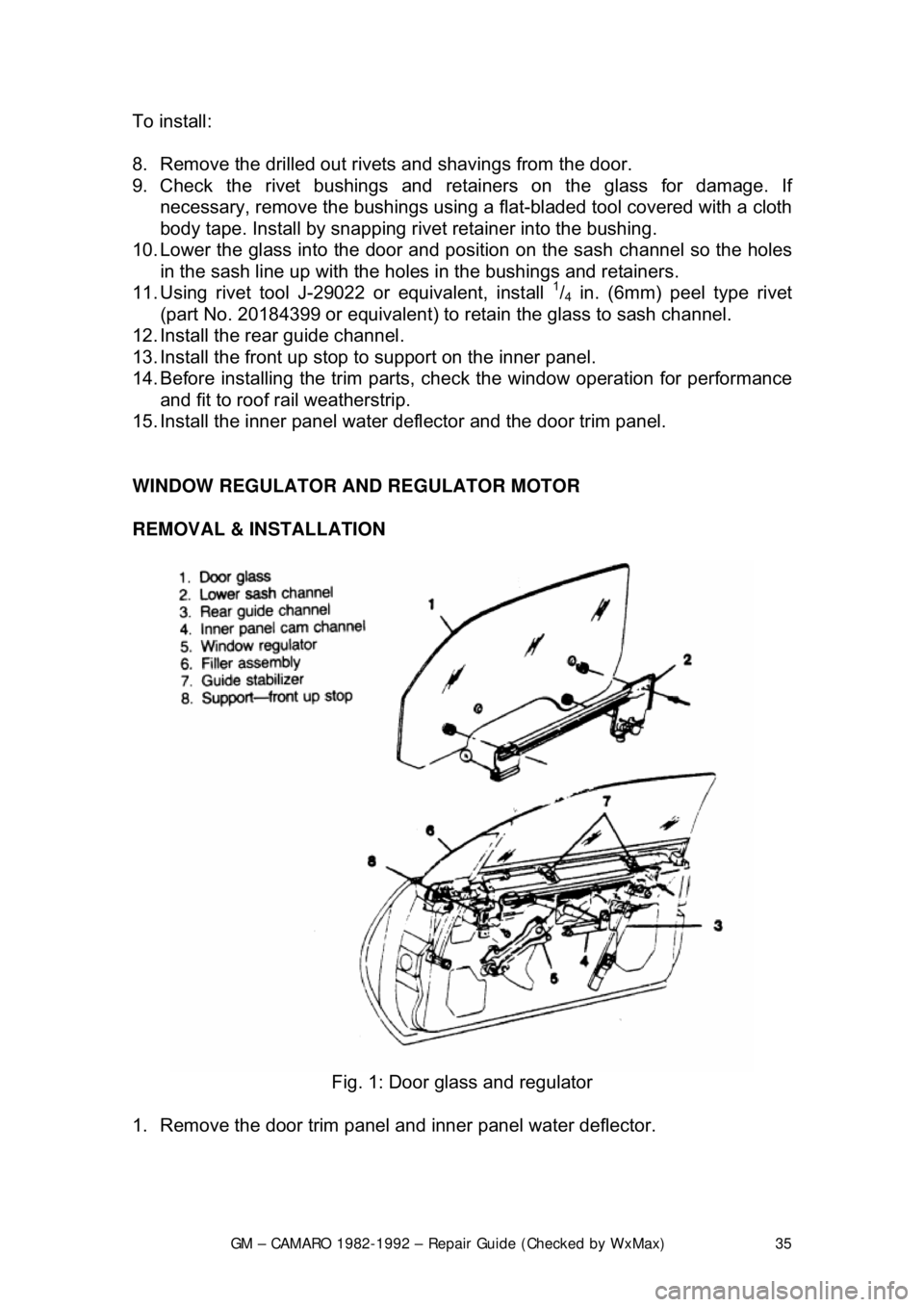
Fig. 1: Door glass and regulator
1. Remove the door trim panel an d inner panel water deflector.