1982 CHEVROLET CAMARO fuel filter
[x] Cancel search: fuel filterPage 411 of 875

GM – CAMARO 1982-1992 – Repair Guide (Checked by WxMax) 411
1. Disconnect the negative battery cable.
2. Relieve the fuel system pressure
and drain the engine coolant from the
radiator into a suitable container.
3. Remove the intake manifold and the spark plugs.
4. Remove the dipstick tube and bra cket. Raise and support the vehicle
safely. Drain the oil and remove the oil filter. Lower the vehicle.
5. Remove the exhaust manifolds.
6. Remove the drive belt(s).
7. Remove the air conditioning compresso r and bracket, reposition it aside.
Do not disconnect the lines.
8. Remove the power steering pump and bracket, reposition it aside.
9. Remove the alternator and br acket, reposition it aside.
10. Remove the ground cable from the rear of the cylinder head and remove
the engine lift bracket.
11. Remove the rocker arm covers.
12. Loosen the rocker arms until the pushrods can be removed.
13. Remove the cylinder head bolts and remove the cylinder heads.
To install: 14. Clean the gasket mating surfaces of all components. Be careful not to
nick or scratch any surfaces as this will allow leak paths. Clean the bolt
threads in the cylinder bl ock and on the head bolts. Dirt will affect bolt
torque.
15. Place the head gaskets in pos ition over the dowel pins.
16. Install the cylinder heads.
17. Coat the cylinder head bolts th reads with GM sealer 1052080 or
equivalent, and install the bolts. Tight en the bolts in the proper sequence
to:
• 1982-1987 engines: 70 ft lbs. (90 Nm)
• 1988-1992 engines: 1st step: 40 ft lbs. (55 Nm); 2nd step: tighten
an additional 1/4 (90 degree) turn
18. Install the pushrods a nd loosely retain them wit h the rocker arms. Make
sure the lower ends of the pushrods ar e in the lifter seats. Refer to the
rocker arm procedures outlined ea rlier in this section.
19. Install the power steering pump br acket and pump. Do the same for the
air conditioning compressor bracket and compressor.
20. Install the ground cable to t he rear of the cylinder head.
21. Install the exhaust manifolds.
22. Install the dipstick tube and bracket.
23. Install the intake manifold.
24. Install the alternator bracket and alternator.
25. Install the drive belt(s).
26. Install the spark plugs.
27. Fill the cooling system with the proper type and quantity of coolant. Install
a new oil filter and fill the crankca se with the proper type and quantity of
oil.
28. Connect the negative battery cable, star t the vehicle and check for leaks.
Page 416 of 875

GM – CAMARO 1982-1992 – Repair Guide (Checked by WxMax) 416
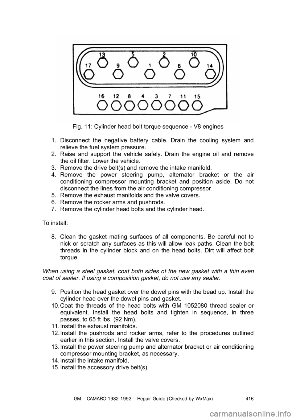
Fig. 11: Cylinder head bolt torque sequence - V8 engines
1. Disconnect the negative battery c able. Drain the cooling system and
relieve the fuel system pressure.
2. Raise and support the vehicle safe ly. Drain the engine oil and remove
the oil filter. Lower the vehicle.
3. Remove the drive belt(s) and remove the intake manifold.
4. Remove the power steering pump, alternator bracket or the air
conditioning compressor mounting br acket and position aside. Do not
disconnect the lines from the air conditioning compressor.
5. Remove the exhaust manifolds and the valve covers.
6. Remove the rocker arms and pushrods.
7. Remove the cylinder head bolts and the cylinder head.
To install: 8. Clean the gasket mating surfaces of all components. Be careful not to
nick or scratch any surfaces as this will allow leak paths. Clean the bolt
threads in the cylinder bl ock and on the head bolts. Dirt will affect bolt
torque.
When using a steel gasket, coat both sides of the new gasket with a thin even
coat of sealer. If using a compos ition gasket, do not use any sealer.
9. Position the head gasket over the dow el pins with the bead up. Install the
cylinder head over the dowel pins and gasket.
10. Coat the threads of the head bo lts with GM 1052080 thread sealer or
equivalent. Install the head bolts and tighten in sequence, in three
passes, to 65 ft lbs. (92 Nm).
11. Install the exhaust manifolds.
12. Install the pushrods and rocker arms, refer to the procedures outlined earlier in this section. Install the valve covers.
13. Install the power steering pump and al ternator bracket or air conditioning
compressor mounting bra cket, as necessary.
14. Install the intake manifold.
15. Install the accessory drive belt(s).
Page 441 of 875

GM – CAMARO 1982-1992 – Repair Guide (Checked by WxMax) 441
2. Remove the fan, driv
e belts and water pump pul ley. Remove the valve
cover. Loosen the rocker arms and pivot them, then remove the
pushrods.
3. Remove the oil pump driveshaft and gear assembly. This is located
under a small plate secured by two bol ts near the oil filter. Remove the
spark plugs.
4. Mark the position of the distribut or rotor, housing, and engine block.
Remove the distributor.
5. Remove the valve lifters. They are located behind the pushrod cover.
6. Remove the timing gear cover.
7. Insert a screwdriver through the holes in the ti ming gear and remove the
2 camshaft thrust plate screws.
8. Pull the camshaft and gear assembly out through the front of the engine
block.
When removing the camshaft, be careful not to damage the camshaft bearings.
9. If the camshaft is to be removed from the timing gear, place the assembly in an arbor press and s eparate. CAUTION When removing the
timing gear from the camshaft, the thrust plate must be positioned so that
the woodruff key does not damage it.
To install: 10. To install the timing gear to the camshaft, press the assembly together
and measure the end clearance. T here should be 0.0015-0.0050 in.
(0.038-0.127mm) between the thrust plate and the camshaft.
If the clearance is less than 0.0015 in. (0 .038mm), replace the spacer ring; if
more than 0.0050 in. (0.127mm), replace the thrust ring.
11. Lubricate the camshaft, bearings, and lifters. Slide the camshaft
assembly into the engine and align the timing marks of the camshaft gear
and crankshaft gear.
12. Complete the installation by reversing the removal procedure.
V6 AND V8 ENGINES 1. Remove the engine from the vehicl e or remove all components from the
front of the engine (radi ator, grille, etc.).
2. Remove the timing gear cover and chain.
3. Mark the distributor rotor, housi ng and engine block, then remove the
distributor. Remove the fuel pump and fuel pump pushrod on carbureted
engines.
4. Remove the intake manifold and valve covers. Loosen the rocker arms
and pivot out of way. Remove the pushrods and valve lifters.
5. Remove the oil pump drive.
6. Slide the camshaft toward the front of the engine (be careful not to
damage the camshaft bearings).
Page 465 of 875

GM – CAMARO 1982-1992 – Repair Guide (Checked by WxMax) 465
Fig. 12: Muffler hanger attachment
ENGINE RECONDITIONING DETE RMINING ENGINE CONDITION
Anything that generates heat and/or friction will eventually burn or wear out (i.e.
a light bulb generates heat, therefore its life span is limited). With this in mind, a
running engine generates trem endous amounts of both; friction is encountered
by the moving and rotating parts inside the engine and heat is created b\
y
friction and combustion of the fuel. Ho wever, the engine has systems designed
to help reduce the effects of heat and fr iction and provide added longevity. The
oiling system reduces the amount of fr iction encountered by the moving parts
inside the engine, while the cooling system reduces heat created by friction and
combustion. If either system is not main tained, a break-down will be inevitable.
Therefore, you can see how regular main tenance can affect the service life of
your vehicle. If you do not drain, flush and refill your cooling system at the
proper intervals, deposits will begin to accumulate in the radiator, thereby
reducing the amount of heat it can extrac t from the coolant. The same applies to
your oil and filter; if it is not changed often enoug h it becomes laden with
contaminates and is unable to properly lubricate the engine. This increases
friction and wear.
There are a number of methods for evaluat ing the condition of your engine. A
compression test can reveal the condition of your pistons, piston rings, cylinder
bores, head gasket(s), valves and valve seat s. An oil pressure test can warn
you of possible engine bearing, or oil pump failures. Excessive oil consumption,
evidence of oil in the engine air intake area and/or bluish smoke from the tail
pipe may indicate worn piston rings, worn valve guides and/or valve seals. As a
general rule, an engine that uses no more than one quart of oil every 1000
miles is in good condi tion. Engines that use one quart of oil or more in less than
1000 miles should first be checked for oil leaks. If any oil leaks are present,
have them fixed before dete rmining how much oil is consumed by the engine,
especially if blue smoke is not visible at the tail pipe.
COMPRESSION TEST
A noticeable lack of engine power, excessive oil consumption and/or poor fuel
mileage measured over an extended period are all indicators of internal engine
Page 559 of 875

GM – CAMARO 1982-1992 – Repair Guide (Checked by WxMax) 559
Fig. 14: Discard the old gasket. Be sure the remove all carbon deposits from the
ports on the EGR valve and the mounting surface
THERMOSTATIC AIR CLEANER (THERMAC)
OPERATION
This system is designed to warm the air entering the carburetor when
underhood temperatures are low, and to ma intain a controlled air temperature
into the carburetor or throttle body at all times. By allowing preheated air to
enter, the amount of time t he choke is on is reduced, resulting in better fuel
economy and lower emissions. Engine warm-up time is also reduced.
The THERMAC system is composed of th e air cleaner body, a filter, sensor
unit, vacuum diaphragm, damper door, a ssociated hoses and connections. Heat
radiating from the exhaust manifold is tr apped by a heat stove and is ducted to
the air cleaner to supply heated air to t he carburetor or throttle body. A movable
door in the air cleaner case snorkel allows air to be drawn in from the heat stove
(cold operation). The door position is co ntrolled by the vacuum motor, which
receives intake manifold vacuum as modulated by the temperature sensor.
A vacuum door which remain s open can cause carburetor icing or poor cold
driveability. A door which remains clos ed during normal engine operating
temperatures can cause sluggishne ss, engine knocking and overheating.
Page 563 of 875

GM – CAMARO 1982-1992 – Repair Guide (Checked by WxMax) 563
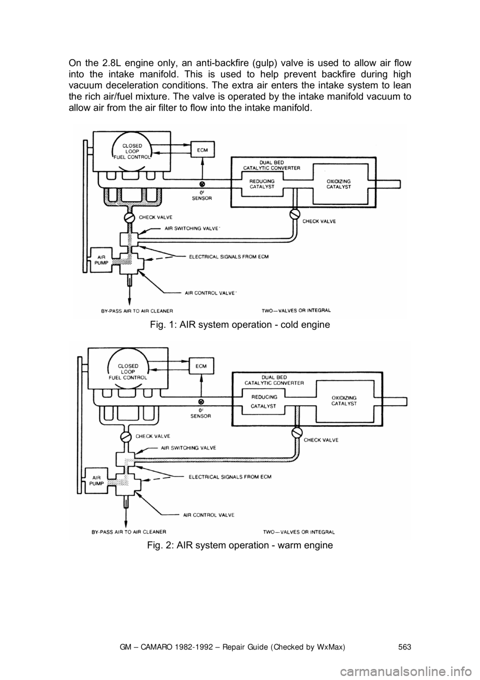
On the 2.8L engine only, an anti-backfire (g
ulp) valve is used to allow air flow
into the intake manifold. This is us ed to help prevent backfire during high
vacuum deceleration conditions. The extra air enters the intake system to lean
the rich air/fuel mixture. The valve is o perated by the intake manifold vacuum to
allow air from the air filter to flow into the intake manifold.
Fig. 1: AIR system operation - cold engine
Fig. 2: AIR system operation - warm engine
Page 668 of 875

GM – CAMARO 1982-1992 – Repair Guide (Checked by WxMax) 668
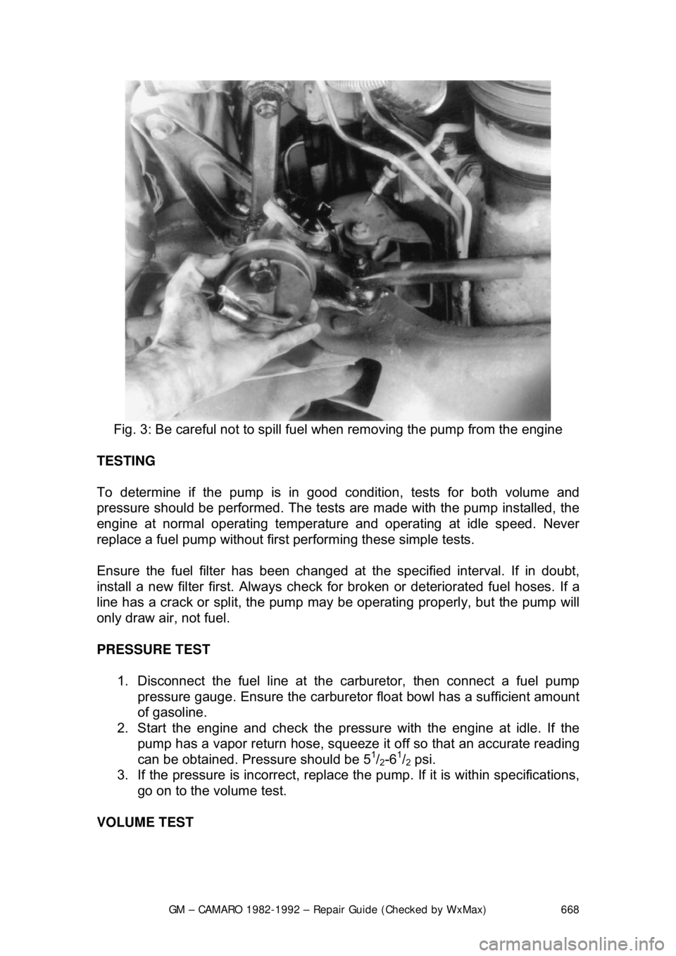
Fig. 3: Be careful not to spill fuel when removing the pump from the engine
TESTING
To determine if the pump is in good condition, tests for both volume and
pressure should be performed. The test s are made with the pump installed, the
engine at normal operating temperatur e and operating at idle speed. Never
replace a fuel pump without first performing these simple tests.
Ensure the fuel filter has been changed at the specified interval. If in doubt,
install a new filter first. Always check fo r broken or deteriorated fuel hoses. If a
line has a crack or split, the pump may be operating properly, but the pump will
only draw air, not fuel.
PRESSURE TEST
1. Disconnect the fuel line at the carburetor, then connect a fuel pump
pressure gauge. Ensure the carburet or float bowl has a sufficient amount
of gasoline.
2. Start the engine and c heck the pressure with the engine at idle. If the
pump has a vapor return hose, squeeze it off so that an accurate reading
can be obtained. Pressure should be 5
1/2-61/2 psi.
3. If the pressure is incorrect, replace t he pump. If it is within specifications,
go on to the volume test.
VOLUME TEST
Page 701 of 875

GM – CAMARO 1982-1992 – Repair Guide (Checked by WxMax) 701
Fig. 32: Throttle position sensor adjusting screw location on E4ME/E4MC
carburetors
REMOVAL & INSTALLATION
Always replace all internal gaskets that are removed. Flooding, stumble on
acceleration and other performance comp laints are in many instances, caused
by presence of dirt, water, or other foreign matter in carburetor. To aid in
diagnosis, carburetor should be carefully removed from engine without draining
fuel from bowl. Contents of fuel bowl may then be examined for contamination
as carburetor is disassembl ed. Check the fuel filter.
ROCHESTER E2SE 1. Remove air cleaner and gasket.
2. Disconnect fuel pipe and vacuum lines.
3. Disconnect electrical connectors.
4. Disconnect accelerator linkage.
5. If equipped with automatic transmi ssion, disconnect downshift cable.
6. If equipped with cruise c ontrol, disconnect linkage.
7. Remove carburetor attaching bolts.
8. Remove carburetor and EF E heater/insulator (if used).
9. Inspect EFE heater/insulator for damage. Be certain throttle body and
EFE heater/insulator surfaces are clean.
To install: 10. Install EFE heater/insulator.
11. Install carburetor and tighten nuts alternately to the correct torque.
12. Connect downshift cable, as required.
13. Attach the cruise cont rol cable, as required.
14. Connect accelerator linkage.
15. Connect electrical connections.