1982 CHEVROLET CAMARO mirror
[x] Cancel search: mirrorPage 13 of 875

GM – CAMARO 1982-1992 – Repair Guide (Checked by WxMax) 13
15. Install the spare tire assembly.
16. Install the rear left, ri
ght and center trim panel.
17. Close the rear compartment hatch.
18. Connect the negative battery cable.
OUTSIDE MIRRORS
REMOVAL & INSTALLATION
STANDARD MIRRORS
Fig. 1: Outside mirrors
1. Remove the door trim panel and det ach inner panel water deflector enough
to gain access to the mi rror retainer nuts.
2. Remove the attaching nuts from the mirror base studs and remove the
mirror assembly from the door.
3. Position the mirror onto the door ma king sure the mirror gasket is properly
aligned on the door outer panel.
4. Install the attaching nuts to the mirror base studs and tighten.
5. Install the inner panel wate r deflector and door trim panel.
REMOTE CONTROL MIRRORS
1. Remove the mirror remote control bezel and door trim panel. Detach the
inner panel water deflector enough to expose the mirror and cable assembly
from the door.
Page 14 of 875

GM – CAMARO 1982-1992 – Repair Guide (Checked by WxMax) 14
2. Remove the mirror base-to-door outer
panel stud nuts, remove the cable
from the clip and remove the mirror and cable assembly from the door.
3. Position the mirror onto the door ma king sure the mirror gasket is properly
aligned on the door outer panel.
4. Install the cable onto the clip and install the mirror base-to-door outer panel
stud nuts. Torque to 72 inch lbs. (8 Nm).
5. Install the inner panel wate r deflector and door trim panel.
6. Install the mirror remote control bezel.
POWER OPERATED MIRRORS
Disconnect the negative battery terminal and, from the door trim panel side,
remove the remote control mirror bezel , release and remove the door panel.
1. Disconnect wire harness connection from t he remote mirror electrical switch.
2. Peel back water deflect or enough to detach the har ness from the retaining
tabs in the door.
3. Remove the mirror base-to-door stud nuts and lift mirror housing and
harness assembly from the door.
To install:
5. feed the mirror harness through the do or along with the mirror assembly.
Install the mirror base-to- door stud nuts and tighten.
6. Connect the mirror wire harness and install the water deflector.
7. Connect the wire harness connection to the remote mirror electrical switch.
8. Install the door panel and install the remote control mirror bezel.
9. Connect the negative battery terminal.
Page 28 of 875

GM – CAMARO 1982-1992 – Repair Guide (Checked by WxMax) 28
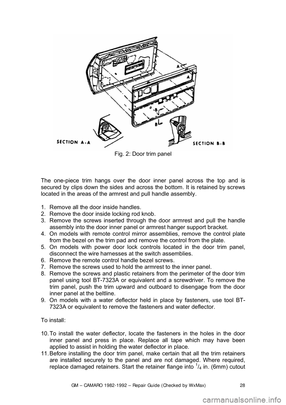
Fig. 2: Door trim panel
The one-piece trim hangs over the door inner panel across the top and is
secured by clips down the sides and across the bottom. It is retained by screws
located in the areas of the armrest and pull handle assembly.
1. Remove all the door inside handles.
2. Remove the door inside locking rod knob.
3. Remove the screws inserted through the door armrest and pull the handle
assembly into the door inner panel or armrest hanger support bracket.
4. On models with remote control mirror assemblies, remove the control plate
from the bezel on the trim pad and remo ve the control from the plate.
5. On models with power door lock contro ls located in the door trim panel,
disconnect the wire harnesses at the switch assemblies.
6. Remove the remote control handle bezel screws.
7. Remove the screws used to hold the armrest to the inner panel.
8. Remove the screws and plastic retainer s from the perimeter of the door trim
panel using tool BT-7323A or equivalent and a screwdriver. To remove the
trim panel, push the trim upward and out board to disengage from the door
inner panel at the beltline.
9. On models with a water deflector held in place by fasteners, use tool BT-
7323A or equivalent to remove th e fasteners and water deflector.
To install:
10. To install the water deflector, locate the fasteners in the holes in the door
inner panel and press in place. R eplace all tape which may have been
applied to assist in holding t he water deflector in place.
11. Before installing the door trim panel, make certain that all the trim retainers
are installed securely to the panel and are not damaged. Where required,
replace damaged retainers. St art the retainer flange into
1/4 in. (6mm) cutout
Page 29 of 875

GM – CAMARO 1982-1992 – Repair Guide (Checked by WxMax) 29
attachment hole in the trim panel, rotate the retainer until the flange is
engaged fully.
12. Connect all electrical components where present.
13. To install the door trim panel, locate the top of the assembly over the upper
flange of the door inner panel, inserting the door handle through the handle
slot in the panel and press down on the trim panel to engage the upper
retaining clips.
14. Position the trim panel to the door inner panel so the trim retainers are
aligned with the attaching holes in t he panel and tap the retainers into the
holes with the palm of hand or a clean rubber mallet.
15. Install the screws used to hold the armrest to the inner panel.
16. Install the remote control handle bezel screws.
17. On models with power door lock contro ls located in the door trim panel,
connect the wire harnesses at the switch assemblies.
18. On models with remote control mirror assemblies, install the control to the
plate. Install the control plate to the bezel on the trim pad.
19. Install the handle assemb ly and install the screws inserted through the door
armrest.
20. Install the door inside locking rod knob.
21. Install all the door inside handles.
HEADLINER
REMOVAL & INSTALLATION
Fig. 1: Headliner installation
1. Disconnect the negative battery cable.
2. Remove the dome lamp and sunshade.
3. Remove the coat hooks and seat bel t escutcheon, by unsnapping from the
headliner.
4. Remove the rear window opening molding.
Page 40 of 875

GM – CAMARO 1982-1992 – Repair Guide (Checked by WxMax) 40
INSIDE REAR VIEW MIRROR
INSTALLATION
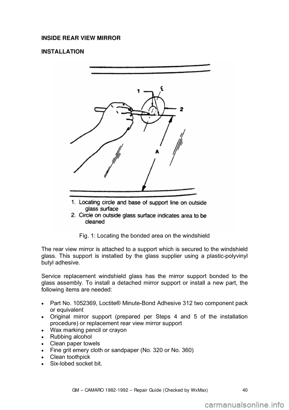
Fig. 1: Locating the bonded area on the windshield
The rear view mirror is attached to a s upport which is secured to the windshield
glass. This support is inst alled by the glass supplier using a plastic-polyvinyl
butyl adhesive.
Service replacement windshield glass has the mirror support bonded to the
glass assembly. To install a detached mi rror support or install a new part, the
following items are needed:
• Part No. 1052369, Loctite® Minute-B ond Adhesive 312 two component pack
or equivalent
• Original mirror support (prepared per Steps 4 and 5 of the installation
procedure) or replacement rear view mirror support
• Wax marking pencil or crayon
• Rubbing alcohol
• Clean paper towels
• Fine grit emery cloth or sandpap er (No. 320 or No. 360)
• Clean toothpick
• Six-lobed socket bit.
Page 41 of 875

GM – CAMARO 1982-1992 – Repair Guide (Checked by WxMax) 41
1. Determine the rear view mirror suppor
t position on the windshield. Support is
to be located at the center of the glass 271/8 in. (69cm) from the base of the
glass to the base of the support.
2. Mark the location on the outside of the glass with wax pencil or crayon.
Make a larger diameter circle around t he mirror support circle on the outside
of the glass surface.
3. On the inside of the glass surface, clean the large circle with a paper towel
and domestic scouring cleanser, gla ss cleaning solution or polishing
compound. Rub until the area is comple tely clean and dry. When dry, clean
the area with an alcohol saturated paper towel to remove any traces of
scouring powder or cleaning solution from this area.
4. With a piece of fine grit (No. 320 or No. 360) emery cloth or sandpaper, sand
the bonding surface of the new rear view mirror support or factory installed
support. If original rear view mirror support is to be reused, all traces of the
factory installed adhesive must be re moved prior to reinstallation.
5. Wipe the sanded mirror support with a clean paper towel saturated with alcohol and allow it to dry.
6. Follow the directions on the manufac turer's kit to prepare the rear view
mirror support prior to inst allation on the glass.
7. Properly position the support to it s premarked location, with rounded end
pointed upward, press the support agai nst the glass for 30-60 seconds,
exerting steady pressure against the gla ss. After five minutes, any excess
adhesive may be removed with an alcohol moistened paper towel or glass
cleaning solution.
8. Install the mirror.
SEATS
REMOVAL & INSTALLATION
1. Operate the seat to the full-forwar d position. If a six-way power seat is
operable, operate the seat to the full-forward and up positions. Where
necessary to gain access to the adjuste r-to-floor pan attaching nuts, remove
the adjuster rear foot covers and/or carpet retainers.
2. Remove the track covers where nec essary; then remove the adjuster-to-
floor pan rear attaching nuts. Operate t he seat to the full-rearward position.
Remove the adjuster front foot covers ; then remove the adjuster-to-floor pan
front attaching nuts.
3. Remove the seat assembly from the car.
4. Check that both seat adjusters ar e parallel and in phase with each other.
5. Install the adjuster-to- floor pan attaching nuts by moving the seat forward
and rearward and torque nuts to 15-21 ft. lbs. (20-28 Nm).
6. Check the operation of the seat a ssembly to full limits of travel.
Page 207 of 875

GM – CAMARO 1982-1992 – Repair Guide (Checked by WxMax) 207
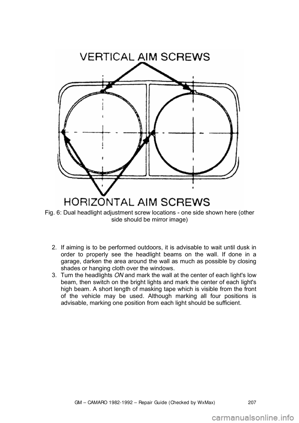
Fig. 6: Dual headlight adjustment screw locations - one side shown here (other
side should be mirror image)
2. If aiming is to be performed outdoors, it is advisable to wait until dusk in
order to properly see t he headlight beams on the wall. If done in a
garage, darken the area around the wall as much as possible by closing
shades or hanging cloth over the windows.
3. Turn the headlights ON and mark the wall at the center of each light's low
beam, then switch on the bright lights and mark the center of each light's
high beam. A short length of masking tape which is visible from the front
of the vehicle may be used. Althoug h marking all four positions is
advisable, marking one position from each light should be sufficient.
Page 551 of 875

GM – CAMARO 1982-1992 – Repair Guide (Checked by WxMax) 551
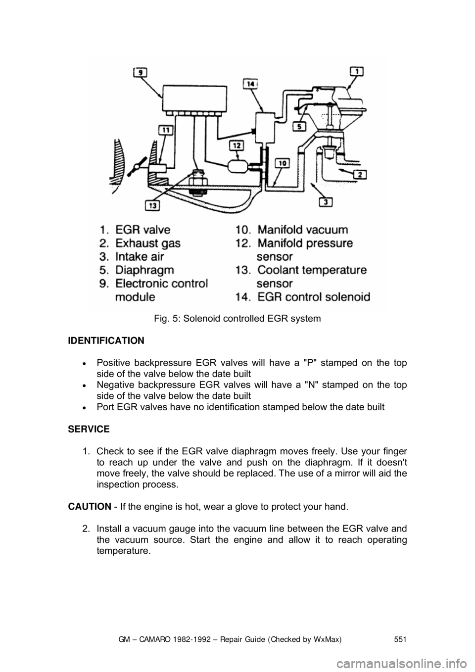
Fig. 5: Solenoid c ontrolled EGR system
IDENTIFICATION
• Positive backpressure EGR valves will have a "P" stamped on the top
side of the valve bel ow the date built
• Negative backpressure EGR valves will have a "N" stamped on the top
side of the valve bel ow the date built
• Port EGR valves have no identificat ion stamped below the date built
SERVICE 1. Check to see if the EGR valve di aphragm moves freely. Use your finger
to reach up under the valve and pus h on the diaphragm. If it doesn't
move freely, the valve should be repl aced. The use of a mirror will aid the
inspection process.
CAUTION - If the engine is hot, wear a glove to protect your hand.
2. Install a vacuum gauge into the vacuum line between the EGR valve and
the vacuum source. Star t the engine and allow it to reach operating
temperature.