1982 CHEVROLET CAMARO steering column
[x] Cancel search: steering columnPage 26 of 875

GM – CAMARO 1982-1992 – Repair Guide (Checked by WxMax) 26
Fig. 3: 1991-92 instrument panel
CAUTION - The 1991-92 vehicles are equipped with an Air Bag system. Proper
disarming of the system is necessary before proceeding with any disassembly
or repairs to the steering column, das h or electrical system or possible
deployment of the air bag might occur. Refer to Suspension & Steering for
disarming procedure.
1. Properly disable t he SIR air bag system, if equipped. Disconnect the
negative battery cable.
2. Remove the center console.
3. Remove the screws attaching the in strument panel pad to the instrument
panel.
4. Remove the daytime running light sens or electrical connector, if equipped.
5. Remove the instrument panel pad.
6. Remove the instrument panel sound insulators.
7. Remove the knee bolster and bracket.
8. Remove the instrument panel cluster.
9. Remove the steering column retaining nuts and lower the column.
10. Remove the upper and lower instrument panel to cowl screws.
11. Disconnect and remove the electric al harness at the cowl connector and
under dash panel.
12. Remove the instrument panel assembly.
To install:
13. Install the instru ment panel assembly.
14. Install the electrical harness at the cowl connector and under dash panel.
15. Install the upper and lower inst rument panel to cowl screws.
16. Install the steering column retaining nuts.
17. Install the instru ment panel cluster.
18. Install the knee bolster and bracket.
Page 73 of 875

GM – CAMARO 1982-1992 – Repair Guide (Checked by WxMax) 73
To install:
9. Install the new line or hose, starti
ng with the end farthest from the master
cylinder. Connect the other end, then confirm that both fittings are correctly
threaded and turn smoothly using finger pressure. Make sure the new line
will not rub against any ot her part. Brake lines must be at least 1/2 in.
(13mm) from the steering column and other moving parts. Any protective
shielding or insulators must be rein stalled in the original location.
WARNING - Make sure the hose is NO T kinked or touching any part of the
frame or suspension after installation. These conditions may cause the hose to
fail prematurely.
10. Using two wrenches as bef ore, tighten each fitting.
11. Install any retaining clips or brackets on the lines.
12. If removed, install the wheel and tire assemblies, then carefully lower the
vehicle to the ground.
13. Refill the brake master cylinder re servoir with clean, fresh brake fluid,
meeting DOT 3 specifications. Pr operly bleed the brake system.
14. Connect the negative battery cable.
BLEEDING
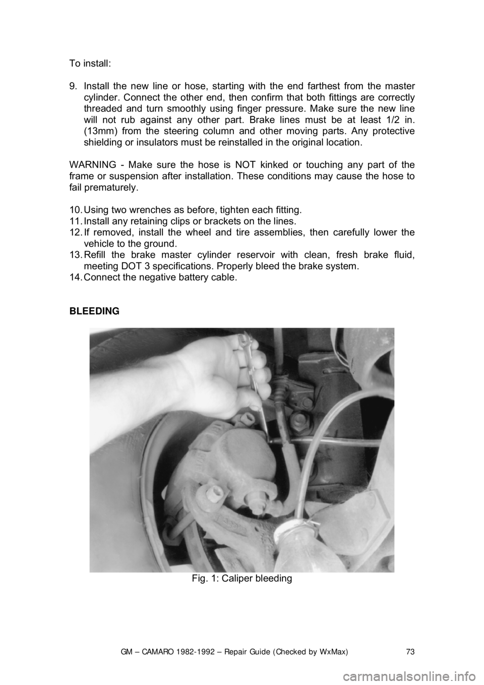
Fig. 1: Caliper bleeding
Page 146 of 875

GM – CAMARO 1982-1992 – Repair Guide (Checked by WxMax) 146
SUPPLEMENTAL INFLATABLE RESTRAINT SYSTEM
GENERAL INFORMATION
All 1990-1992 models are equi
pped with an airbag system. The Supplemental
Inflatable Restraint (SIR) syst em helps supplement the protection offered by the
seat belts by deploying an ai r bag from the center of the steering wheel. The air
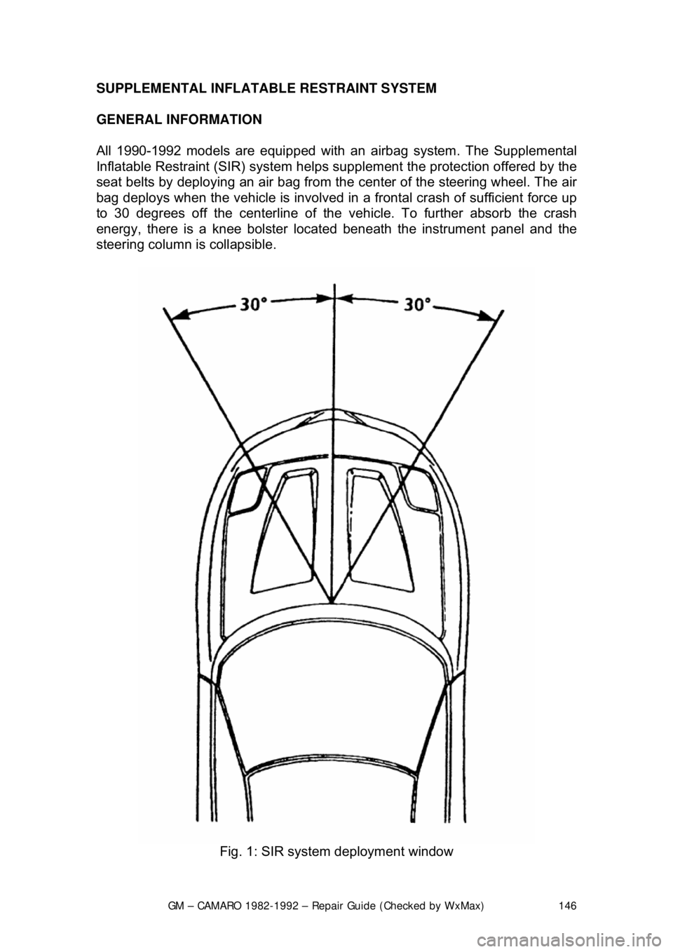
bag deploys when the vehicle is involved in a frontal crash of sufficient force up
to 30 degrees off the center line of the vehicle. To further absorb the crash
energy, there is a knee bolster located beneath the instrument panel and the
steering column is collapsible.
Fig. 1: SIR system deployment window
Page 148 of 875

GM – CAMARO 1982-1992 – Repair Guide (Checked by WxMax) 148
ARMING SENSOR
The arming sensor is a protective switch
located in the power feed side of the
deployment loop. It is calibrated to clos e at low level velocity changes (lower
than the discriminating sens ors). This assures that the inflator module is
connected directly to the 36 volt output of the DERM or battery voltage feed
when either of the discrim inating sensors close.
DISCRIMINATING SENSORS
The discriminating sensors are wired in parallel on the ground side of the
deployment loop. These sensors are calib rated to close with velocity changes
which are severe enough to warrant deployment.
SIR COIL ASSEMBLY
The SIR coil assembly consists of two cu rrent carrying coils. They are attached
to the steering column and allow rotation of the steering wheel while maintaining
continuous contact of the deployment loop to the inflator module.
INFLATOR MODULES
Each inflator module consists of an inflat able bag and an inflator (a canister of
gas generating material with an initiati ng device). When the vehicle is in a
frontal crash of sufficient force, current flows through the deployment loops.
Current flowing through the initiator ignite s the material in the inflator module.
The gas produced from this reaction rapidly inflates the air bag.
Fig. 2: Forward discriminating se nsor location on 1990-1992 models
Page 149 of 875

GM – CAMARO 1982-1992 – Repair Guide (Checked by WxMax) 149
Fig. 3: Passenger com partment SIR component lo cations on 1990-1992 models
SERVICE PRECAUTIONS
The DERM can maintain sufficient volt age to cause a deployment for up to 10
minutes after the ignition switch is tur ned OFF or the battery is disconnected.
Always disable the system when perfo rming service procedures ON OR NEAR
the system and it's components.
CAUTION - The disarming and arming procedures must be followed in the
order listed to temporarily disable the SI R system. Failure to do so could result
in possible air bag deployment, pers onal injury or otherwise unneeded SIR
system repairs.
DISARMING THE SYSTEM
1. Turn the steering wheel so that t he vehicle's wheels are pointing straight
ahead.
2. Turn the ignition switch to the LOCK position.
3. Remove the SIR or AIR BAG fuse from the fuse panel.
4. Remove the left side trim panel, t hen remove the Connector Position
Assurance (CPA) device and disconnec t the yellow two-way SIR harness
connector at the base of the steering column.
5. On vehicles with passenger side air bags, remove the glove box door
then disconnect the yellow two-way c onnector located near the yellow
24-way DERM harness connector.
With the fuse removed and the ignition sw itch ON, the air bag warning lamp will
be on. This is normal and does not indicate a SIR system malfunction.
Page 151 of 875

GM – CAMARO 1982-1992 – Repair Guide (Checked by WxMax) 151
ARMING THE SYSTEM
1. Turn the ignition key to the LO CK position and remove the key.
2. On vehicles with a passenger side ai r bag, reconnect the yellow two-way
connector assembly located near the yellow 24-way DERM harness
connector. Install the glov e box door assembly.
3. Connect the yellow two-way connector assembly at the base of the
steering column.
Always be sure to reinstall the Connec tor Position Assurance (CPA) device.
4. Install the left side trim panel and rein stall the fuse in the fuse block.
5. Turn the ignition key to the RUN posit ion and verify that the warning lamp
flashes seven to nine times and then turn s OFF. If it does not operate as
described, have the system repair ed by a qualified technician.
HEATING AND AIR CONDITIONING
BLOWER MOTOR
REMOVAL & INSTALLATION 1. Disconnect the negative battery cable. If necessary, remove the diagonal
fender brace at the right rear corner of the engine compartment to gain
access to the blower motor.
2. Disconnect the electrical wiring fr om the blower motor. If equipped with
air conditioning, remove the blower relay and bracket as an assembly
and swing them aside.
3. Remove the blower motor cooling tube.
4. Remove the blower mo tor retaining screws.
5. Remove the blower motor and fan as an assembly from the case.
To install: 6. Position the blower motor into pl ace and install the retaining screws.
7. Install the blower motor cooling tube.
8. Connect all the electrical connections.
9. Connect the negative battery cable.
Page 160 of 875

GM – CAMARO 1982-1992 – Repair Guide (Checked by WxMax) 160
damage, and legal considerations (such as t
he fact that it is a federal crime to
vent refrigerant into the atmosphere), dictate that the A/C components on your
vehicle should be serviced only by a Motor Vehicle Air Conditioning (MVAC)
trained, and EPA certified aut omotive technician.
If your vehicle's A/C system uses R-12 re frigerant and is in need of recharging,
the A/C system can be c onverted over to R-134a refrigerant (less
environmentally harmful and expensive). Refer to General Information &
Maintenance for additional information on R- 12 to R-134a conversions, and for
additional considerations dealing with your vehicle's A/C system.
CONTROL CABLES
REMOVAL & INSTALLATION
Some of the following cables will not be used on all models and model years.
Left and Right Air Vent Cables 1. Remove the left and right sound insulators.
2. Remove the screws attaching the cabl es to the steering column cover.
3. Disengage the cable clamps at the vent ducts.
4. Disengage the Z-shaped c able ends from the vent valve levers.
5. Remove the air vent cables notin g their positions for installation.
To install: 6. Place the cables in posi tion under the instrument panel.
7. Engage the Z-shaped cable ends to the vent valve levers.
8. Snap the cable clamps into the slot of the bracket formed on the vent
ducts.
9. Attach the air vent cables at the steering column cover.
10. Install the sound insulators and test cable operation.
Fig. 1: Cable attachment at the steering column cover
Page 176 of 875

GM – CAMARO 1982-1992 – Repair Guide (Checked by WxMax) 176
Fig. 1: mounting of cruise control module
MULTI-FUNCTION LEVER
REMOVAL & INSTALLATION 1. Disconnect the negative battery terminal.
2. Disconnect cruise control switch connector at the base of steering
column. It may be necessary to re move an under dash panel or trim
piece for access.
3. Make sure the lever is in the OFF position.
4. Pull the lever straight out of the retaining clip within the steering column.
5. Attach mechanic's wire or simi lar to the connector; gently pull the
harness through the column, leaving the pull wire in place.
To install: 6. Attach the mechanic's wire to the connector. Gently pull the harness into
place, checking that the harness is completely clear of any moving or
movable components such as tilt column, telescoping column, brake
pedal linkage, etc.
7. Position the lever and push it squarely into the re tainer until it snaps in
place.
8. Remove the mechanics' wire and connect the cruise control harness
connector.
9. Reinstall any panels or insulation which were removed for access.
10. Connect the negative battery terminal.