1982 CHEVROLET CAMARO set clock
[x] Cancel search: set clockPage 145 of 875

GM – CAMARO 1982-1992 – Repair Guide (Checked by WxMax) 145
When the battery cable(s) are reconnecte
d (negative cable last), be sure to
check that your lights, windshield wipers and other electrically operated safety
components are all working correctly. If your vehicle contains an Electronically
Tuned Radio (ETR), don't forget to also reset your radio stations. Ditto for the
clock.
Page 629 of 875

GM – CAMARO 1982-1992 – Repair Guide (Checked by WxMax) 629
as much voltage to fire the plug at hi
gh speeds than at idle. The improved
air/fuel ratio control of modern fuel injection combin ed with the higher voltage
output of modern ignition systems will often allow an engine to run significantly
longer on a set of standard spark plugs, but keep in mind that efficiency will
drop as the gap widens (along wit h fuel economy and power).
When you're removing spark plugs, work on one at a time. Don't start by
removing the plug wires all at once, because, unless you number them, they
may become mixed up. Take a minute before you begin and number the wires
with tape.
1. Disconnect the negative battery cabl e, and if the vehicle has been run
recently, allow the engine to thoroughly cool.
2. Carefully twist the spark plug wire boot to loosen it, then pull upward and
remove the boot from the plug. Be su re to pull on the boot and not on the
wire, otherwise the connector locat ed inside the boot may become
separated.
3. Using compressed air, blow any water or debris from the spark plug well
to assure that no harmful contam inants are allowed to enter the
combustion chamber when the spark plug is removed. If compressed air
is not available, use a rag or a brush to clean the area.
Remove the spark plugs when the engine is cold, if possible, to prevent damage
to the threads. If removal of the plugs is difficult, apply a few drops of
penetrating oil or silicone spray to t he area around the base of the plug, and
allow it a few minutes to work.
4. Using a spark plug socket that is equipped with a rubber insert to
properly hold the plug, turn the spar k plug counterclockwise to loosen
and remove the spark pl ug from the bore.
WARNING - Be sure not to use a flexible extension on the socket. Use of a
flexible extension may allow a shear fo rce to be applied to the plug. A shear
force could break the plug off in the cylinder head, leading to costly a\
nd
frustrating repairs.
To install:
5. Inspect the spark plug boot for t ears or damage. If a damaged boot is
found, the spark plug wire must be replaced.
6. Using a wire feeler gauge, check and adjust the spark plug gap. When
using a gauge, the proper size shoul d pass between the electrodes with
a slight drag. The next larger size should not be able to pass while the\
next smaller size should pass freely.
7. Carefully thread the plug into the bor e by hand. If resistance is felt before
the plug is almost completely th readed, back the plug out and begin
threading again. In small, hard to r each areas, an old spark plug wire and
boot could be used as a th reading tool. The boot will hold the plug while
you twist the end of the wire and t he wire is supple enough to twist
before it would allow t he plug to crossthread.
Page 672 of 875

GM – CAMARO 1982-1992 – Repair Guide (Checked by WxMax) 672
ROCHESTER E4ME AND E4MC
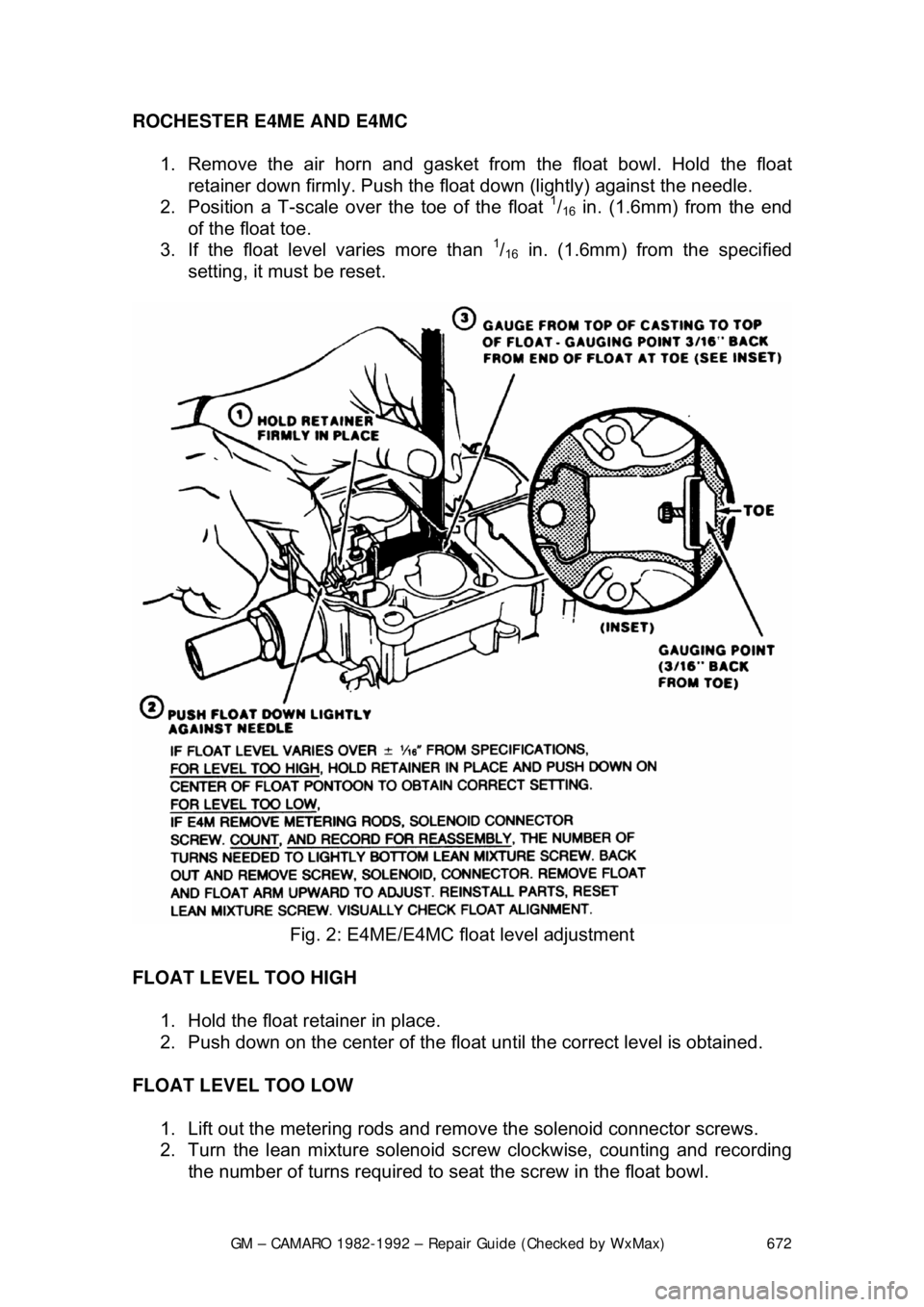
1. Remove the air horn and gasket from the float bowl. Hold the float retainer down firmly. Push the float down (lightly) against the needle.
2. Position a T-scale ov er the toe of the float
1/16 in. (1.6mm) from the end
of the float toe.
3. If the float level varies more than
1/16 in. (1.6mm) from the specified
setting, it must be reset.
Fig. 2: E4ME/E4MC float level adjustment
FLOAT LEVEL TOO HIGH 1. Hold the float retainer in place.
2. Push down on the center of the float until the correct level is obtained.
FLOAT LEVEL TOO LOW 1. Lift out the metering rods and remo ve the solenoid connector screws.
2. Turn the lean mixture solenoid screw clockwise, counting and recording
the number of turns required to seat the screw in the float bowl.
Page 673 of 875

GM – CAMARO 1982-1992 – Repair Guide (Checked by WxMax) 673
3. Turn the screw counterclockwise and
remove it. Lift the solenoid and the
connector from the float bowl.
4. Remove the float and bend the arm up to adjust. The float must be
correctly aligned after adjustment.
5. To install the components, reverse the order of removal. Back out the
solenoid mixture screw t he number of turns that wa s recorded earlier.
THROTTLE LINKAGE
ROCHESTER E2SE
No adjustment of the thro ttle cable can be made.
ROCHESTER E4ME AND E4MC
Due to the design of the throttle cable, no adjustments of the throttle linkage can
be made.
CHOKE UNLOADER (PRIMARY)
ROCHESTER E2SE
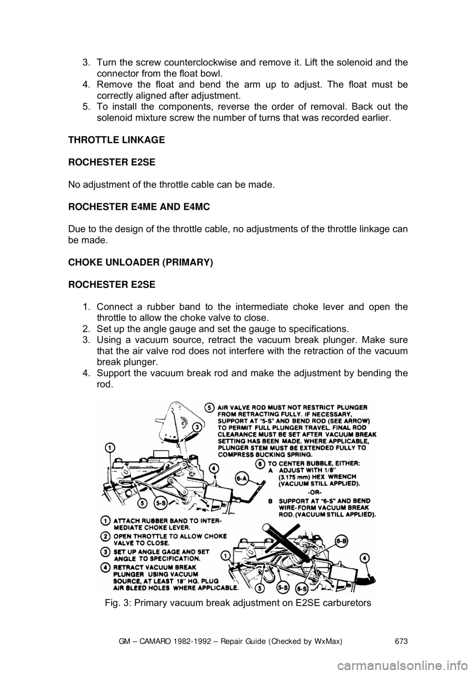
1. Connect a rubber band to the in termediate choke lever and open the
throttle to allow the choke valve to close.
2. Set up the angle gauge and set the gauge to specifications.
3. Using a vacuum source, retract the vacuum break plunger. Make sure
that the air valve rod does not interf ere with the retraction of the vacuum
break plunger.
4. Support the vacuum br eak rod and make the adjustment by bending the
rod.
Fig. 3: Primary vacuum break adjustment on E2SE carburetors
Page 676 of 875

GM – CAMARO 1982-1992 – Repair Guide (Checked by WxMax) 676
ROCHESTER E4ME AND E4MC
1. Connect a rubber band to the green tang of the intermediate choke shaft.
2. Open the throttle to allow the choke valve to close.
3. Set up the angle gauge and set the angle to specification.
4. Using a vacuum source, retr act the vacuum break plunger.
The air valve rod must not restrict the vacuum break plunger from fully
retracting.
5. With the vacuum applied, turn t he adjusting screw or bend the vacuum
break rod until the bubble of t he angle gauge is centered.
Fig. 6: Secondary vacuum break adj ustment on E4ME/E4MC carburetors
AIR VALVE SPRING ADJUSTMENT
ROCHESTER E2SE 1. If necessary, remove the intermediat e choke rod to gain access to the
lock screw.
2. Loosen the lock screw and turn t he tension adjusting screw clockwise
until the air valve opens slightly.
3. Turn the adjusting screw counterclo ckwise until the air valve just closes;
continue turning the screw counterclock wise according to specifications.
4. Tighten the lock screw. Apply lithium grease to the spring and pin.
Page 678 of 875

GM – CAMARO 1982-1992 – Repair Guide (Checked by WxMax) 678
ROCHESTER E4ME AND E4MC
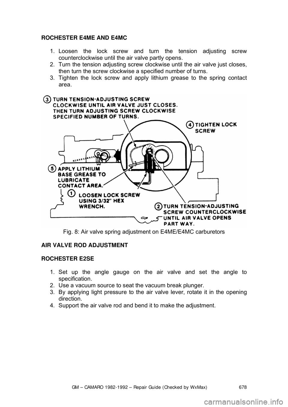
1. Loosen the lock screw and turn the tension adjusting screw counterclockwise until the air valve partly opens.
2. Turn the tension adjus ting screw clockwise until t he air valve just closes,
then turn the screw clockwise a specified number of turns.
3. Tighten the lock screw and apply lithium grease to the spring contact
area.
Fig. 8: Air valve spring adjus tment on E4ME/E4MC carburetors
AIR VALVE ROD ADJUSTMENT
ROCHESTER E2SE 1. Set up the angle g auge on the air valve and set the angle to
specification.
2. Use a vacuum source to s eat the vacuum break plunger.
3. By applying light pressure to the ai r valve lever, rotate it in the opening
direction.
4. Support the air valve rod and bend it to make the adjustment.
Page 689 of 875

GM – CAMARO 1982-1992 – Repair Guide (Checked by WxMax) 689
c. Foreign material in jets
3. Remove throttle side metering rod. Install mixture control solenoid
gauging tool, J-33815-1, BT-8253-A, or equi valent, over the throttle side
metering jet rod guide and temporarily reinstall the solenoid plunger into
the solenoid body.
4. Holding the solenoid plunger in the DOWN position, use tool J-28696-10,
BT-7928, or equivalent, to turn lean mixture solenoid screw
counterclockwise until the plunger br eaks contact with the gauging tool.
Turn slowly clockwise until the pl unger makes contact with the gauging
tool. The adjustment is correct when t he solenoid plunger is contacting
both the solenoid stop and the gauging tool.
If the total difference in adjustment required less than
3/4 turn of the lean mixture
solenoid screw, the original setting was within the manufacturer's specifications.
5. Remove solenoid plunger and gaugi ng tool and reinstall metering rod
and plastic filler block.
6. Invert air horn and remove rich mixt ure stop screw from bottom side of
air horn, using tool J-28696-4, BT-7967-A, or equivalent.
7. Remove lean mixture screw plug and the rich mixture stop screw plug
from air horn, using a punch.
8. Reinstall rich mixtur e stop screw in air horn and bottom lightly, then back
screw out
1/4 turn.
9. Reinstall air horn gasket, mixture c ontrol solenoid plunger and air horn to
carburetor.
10. Adjust the M/C solenoid pl unger travel as follows:
a. Insert float gauge down D- shaped vent hole. Press down on
gauge and release, observing th at the gauge moves freely and
does not bind. With gauge released, (plunger UP position), read at
eye level and record the reading of the gauge mark (in
inches/millimeters) that lines up with the top of air horn casting,
(upper edge).
b. Lightly press dow n on gauge until bottomed, (plunger DOWN
position). Read and record (in inc hes/millimeters) the reading of
the gauge mark that lines up with top of air horn casting.
c. Subtract gauge UP position from the gauge DOWN position and
record the difference. This difference is the total plunger travel.
Insert external float gauge in vent hole and, with tool J-28696-10,
BT-7928, or equivalent, adjust rich mixture stop screw to obtain
5/32 in. (3.9mm) total plunger travel.
11. With solenoid plunger travel corre ctly set, install plugs (supplied in
service kits) in the air horn, as follows:
a. Install plug, hollow end down, into the access hole for the lean
mixture (solenoid) screw. Use suit ably sized punch to drive plug
into the air horn until t he top of plug is even with the lower. Plug
must be installed to retain the sc rew setting and to prevent fuel
vapor loss.
Page 692 of 875

GM – CAMARO 1982-1992 – Repair Guide (Checked by WxMax) 692
IDLE AIR VALVE
A cover is in place over t
he idle air bleed valve. Also , the access holes to the
idle mixture needles are s ealed with hardened plugs. This is done to seal the
factory settings, during original equipment production. These items are NOT to
be removed unless required for cleaning, part replacement, improper dwell
readings or if the System Performance Check indicates the carburetor is the
cause of the trouble.
ROCHESTER E4ME AND E4MC
1. With engine OFF, cover the internal bowl vents and inlet to bleed valve
and the carburetor air intakes with maski ng tape. This is done to prevent
metal chips from entering.
2. Carefully drill rivet head of idle air bleed cover, with 0.110 in. (2.8mm) drill bit.
3. Remove rivet head and all pieces of rivet.
4. Lift cover off air bleed valve and bl ow out any metal shavings, or use a
magnet to remove excess metal.
CAUTION - Always wear eye protection when using compressed air.
5. Remove masking tape.
6. Start engine and allow it to reac h normal operating temperature.
7. Disconnect the vacuum hose from t he canister purge valve and plug it.
8. While idling in D for automatic transmission or N for manual
transmission, slowly turn the valve c ounterclockwise or clockwise, until
the dwell reading varies within the 25-35 degree range, attempting to be
as close to 30 degrees as possible.
Perform this step carefully. The air bleed valve is very sensitive and should be
turned in
1/8 turn increments only.
9. If the dwell reading d oes not vary and is not within the 25-35 degree
range, it will be necessary to remove the plugs and to adjust the idle
mixture needles.