1982 CHEVROLET CAMARO height
[x] Cancel search: heightPage 10 of 875

GM – CAMARO 1982-1992 – Repair Guide (Checked by WxMax) 10
6. Connect the harness connector for the el
ectric grid defogger, if equipped,
and connect the gas supports to the lift window assembly.
7. Lower the lid and check alignment.
ADJUSTMENT
The rear compartment lift window assembly height, fore and aft and side \
adjustments are controlled at the hinge-to-b ody location. This area of the body
has oversize hinge attaching holes in addition to the hinge-to-body spacers.
Adjustments at the hinge location mu st be made with the gas supports
disengaged. Additional height adjustment can also be made at the lower panel
by adjusting the rubber bumpers. Bolt s holding hinge-to-body should be
tightened to 15-20 ft. lbs. (20-28 Nm).
BUMPERS
REMOVAL & INSTALLATION
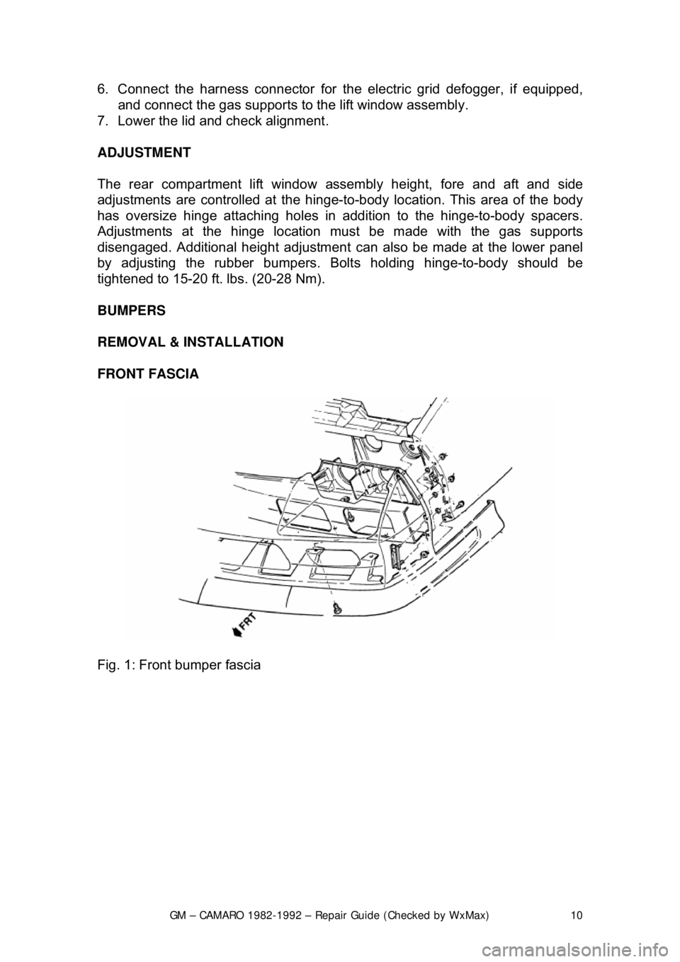
FRONT FASCIA
Fig. 1: Front bumper fascia
Page 485 of 875

GM – CAMARO 1982-1992 – Repair Guide (Checked by WxMax) 485
CYLINDER HEAD
There are several things to check on
the cylinder head: valve guides, seats,
cylinder head surface flatness, cracks and physical damage.
VALVE GUIDES
Now that you know the valves are good, you can use them to check the guides,
although a new valve, if available, is preferred. Before you measure anything,
look at the guides carefully and inspect t hem for any cracks, chips or breakage.
Also if the guide is a removable style (a s in most aluminum heads), check them
for any looseness or evidence of movem ent. All of the guides should appear to
be at the same height from the spring s eat. If any seem lower (or higher) from
another, the guide has moved. Mount a dial indicator onto the spring side of the
cylinder head. Lightly oil the valve stem and insert it into the cylinder head.
Position the dial indicator against the valve stem near the tip and zero the
gauge. Grasp the valve stem and wiggle towards and away from the dial
indicator and observe the readings. Mount the dial indicator 90 degrees from
the initial point and zero the gauge and again take a reading. Compare the two
readings for a out of round condition. Check the readings against the
specifications given. An Inside Diamete r (I.D.) gauge designed for valve guides
will give you an accurate valve guide bore measurement. If the I.D. gauge is
used, compare the readings wit h the specifications given. Any guides that fail
these inspections should be replaced or machined.
Fig. 11: A dial gauge may be used to che ck valve stem-to-guide clearance; read
the gauge while moving the valve stem
Page 799 of 875

GM – CAMARO 1982-1992 – Repair Guide (Checked by WxMax) 799
The master cylinder is located in
the left rear section of the engine
compartment. The brake master cylinder consists of an aluminum body and a
translucent nylon reservoir with minimum fill indicators.
1. Check the master cylinder body for cracks. Inspect the area around the
master cylinder for brake fluid. Leaks are indicated if there is at least a
drop of fluid. A damp condition is not normal.
2. Inspect the level of the brake fluid to assure it is at the correct height.
Clean the top of the reservoir cap so t hat all dirt is removed. Remove the
cap(s) or reservoir cover and the reservoir diaphragm.
3. Inspect the brake fluid level. Add clean DOT-3 brake fluid as required to
bring the fluid level to the line located inside the neck of the reservoir fill
opening.
4. Install the reservoir cap.
WARNING - Any sudden decrease in the fluid level indicates a possible leak in
the system and should be check ed out immediately. Do not allow brake fluid to
spill on the vehicle's finish; it will remove the paint. In case of a spill, flush the
area with water and mild soap.
HYDRAULIC CLUTCH SYSTEM
FLUID RECOMMENDATIONS
• 1982-1991 - Delco Supreme II Brake fl uid or an equivalent fluid that
meets DOT-3 specifications
• 1992 - Hydraulic clutch fluid, GM part number 12345347 or equivalent
LEVEL CHECK
The clutch master cylinder is normally lo cated below the brake master cylinder.
The reservoir for it is located right bes ide the brake master cylinder and is made
of translucent nylon. The fl uid level of the reservoir sh ould be kept near the top
of the observation window. Before removing the cap to the reservoir, clean all
dirt from the area. This will prevent syst em contamination due to particles falling
into the reservoir when the caps are removed.
POWER STEERING PUMP
FLUID RECOMMENDATIONS
• GM power steering fluid, or equivalent.
Page 825 of 875

GM – CAMARO 1982-1992 – Repair Guide (Checked by WxMax) 825
5. Disconnect the tie rod from the
steering knuckle using a ball joint
remover.
6. Using an internal fit coil spring co mpressor, compress the coil spring so
that it is loose in its seat.
CAUTION - Be sure to follow manufacturer' s instructions when using spring
compressor. Coil springs in a comp ressed state contain enormous energy
which, if released accidentally, could cause serious injury.
7. To remove the coil spring, disc onnect the lower control arm from the
crossmember at the pivot bolts. If additional clearance is necessary,
disconnect the lower control arm from the steering knuckle at the ball
joint.
To install: 8. Compress the coil spring until spri ng height is the same as when
removed, then position the spring on the control arm. Make sure the
lower end of the coil spring is properly positioned in the lower control arm
and that the upper end fits correctly in its pad.
9. Connect the lower control arm from t he steering knuckle at the ball joint.
Connect the lower control arm from t he crossmember at the pivot bolts
and install the coil spring.
10. Connect the tie rod to the steering knuckle.
11. Attach the steering gear unit.
12. Connect the stabilizer link to the lower control arm.
13. Install the wheel(s).
14. Lower the vehicle.
Page 841 of 875

GM – CAMARO 1982-1992 – Repair Guide (Checked by WxMax) 841
1. Jack up the car to a convenient working height. Support the axle
assembly with jackstands.
2. Disconnect the upper s hock attaching nuts.
3. Remove the lower shock to axle mounting bolt.
4. Remove the shock absorber.
To install: 5. Position the shock into place.
6. Install the lower shoc k to axle mounting bolt. Torque to 70 ft. lbs. (95
Nm).
7. Connect the upper shock attaching nuts. Torque the upper nuts to 13 ft.
lbs. (17 Nm).
8. Lower the car.
TESTING
Visually inspect the shock absorber. If there is evidence of leakage and the
shock absorber is covered with oil, t he shock is defective and should be
replaced.
If there is no sign of excessive leakage (a small amount of weeping is normal)
bounce the car at one corner by pressi ng down on the fender or bumper and
releasing. When you have the car bouncing as much as you can, release it. The
car should stop bouncing after the first rebound. If the bouncing continues past
the center point of the bounce more t han once, the shock absorbers are worn
and should be replaced.
Page 843 of 875

GM – CAMARO 1982-1992 – Repair Guide (Checked by WxMax) 843
TRACK BAR BRACE
REMOVAL & INSTALLATION
1. Raise the rear of the vehicle, pl ace jackstands under the rear axle, then
lower the jack so that the stands are supporting all of the weight.
2. Remove the heat shield screw s from the track bar brace.
3. Remove the three track bar brace-to-body brace screws.
4. Remove the track bar-to-body bra cket fasteners and remove the track
bar brace.
To install: 5. Place the track bar brace into position.
6. Install the track bar-to-body bracket fasteners.
7. Install the three track bar brace-to-body brace screws.
8. Install the heat shield scre ws to the track bar brace.
9. Lower the vehicle.
CONTROL ARM
REMOVAL & INSTALLATION
Remove/reinstall only one lower control ar m at a time. If both arms are removed
at the same time, the axle could roll or slip sideways, making reinstallation of
the arms very difficult.
1. Raise the rear of the vehicle, pl ace jackstands under the rear axle, then
lower the jack so that the stands are supporting all of the weight.
2. Remove the control arm attachi ng fasteners, then remove the control
arm.
3. Installation is a simple matter of bol ting the arm into place. Torque the 3
bolts at the body brace bracket to 35 ft. lbs. (47 Nm) and the nut at the
body bracket to 61 ft. lbs. (83 Nm).
TORQUE ARM
REMOVAL & INSTALLATION
The coil springs must be removed BEFORE the torque arm. If the torque arm is
removed first, vehicle damage will result. In order to proceed, the vehicle must
be supported in a manner whic h will allow the rear axle height to be adjusted
independently of the body height.
1. Remove the track bar mounting bolt at the axle assembly, then loosen
the track bar bolt at the body brace.
2. Disconnect the rear brake hose clip at the axle assembly, which will allow
additional drop of the axle.
3. Remove the lower attaching nuts from both rear shock absorbers.
4. Disconnect the shock absorbers from their lower attaching points.
Page 859 of 875

GM – CAMARO 1982-1992 – Repair Guide (Checked by WxMax) 859
REMOVAL & INSTALLATION
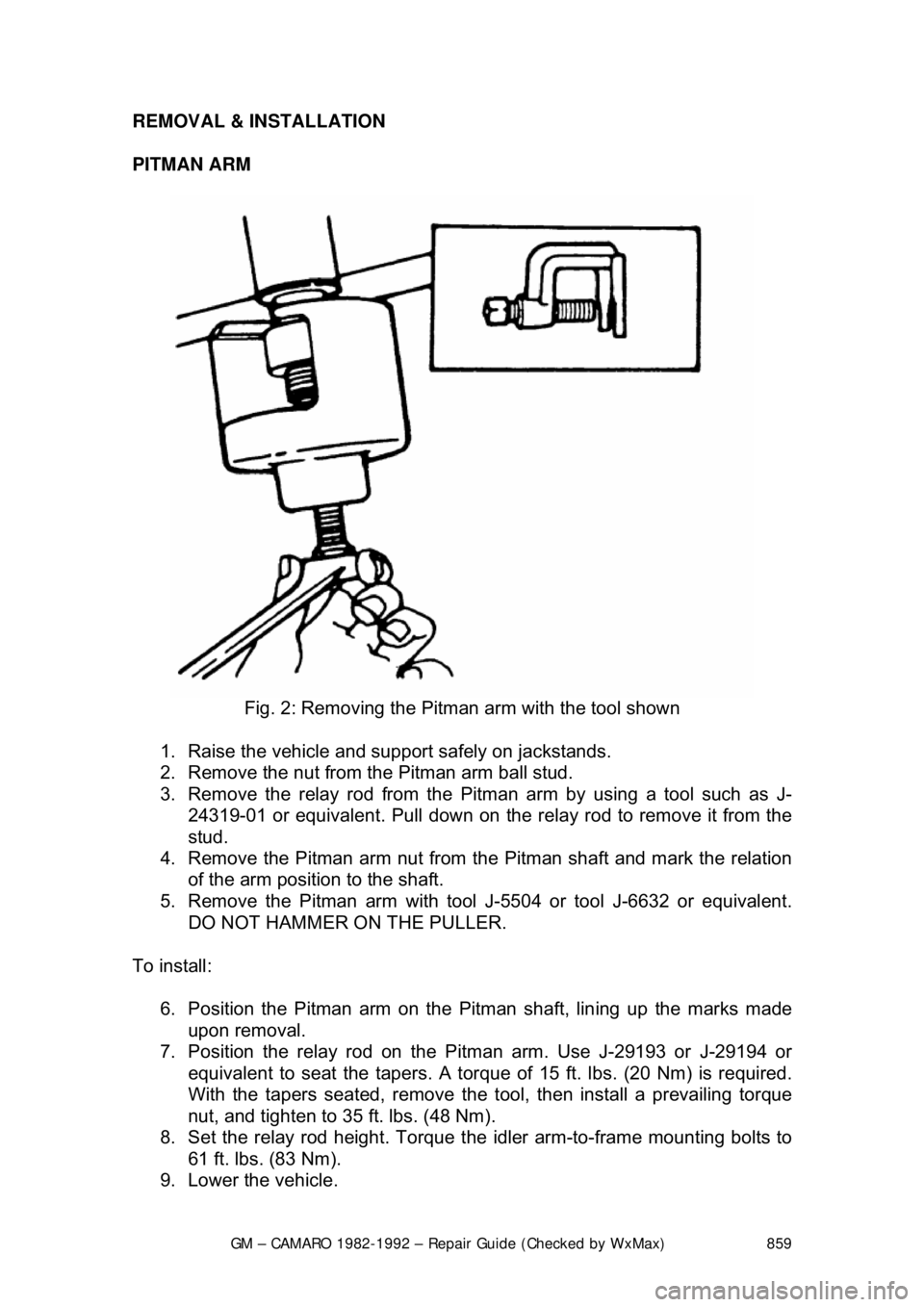
PITMAN ARM
Fig. 2: Removing the Pitman arm with the tool shown
1. Raise the vehicle and support safely on jackstands.
2. Remove the nut from the Pitman arm ball stud.
3. Remove the relay rod from the Pitman arm by us ing a tool such as J-
24319-01 or equivalent. Pull down on the relay rod to remove it from the
stud.
4. Remove the Pitman arm nut from the Pitman shaft and mark the relation
of the arm position to the shaft.
5. Remove the Pitman arm with tool J-5504 or tool J-6632 or equivalent.
DO NOT HAMMER ON THE PULLER.
To install: 6. Position the Pitman arm on the Pitman shaft, lin ing up the marks made
upon removal.
7. Position the relay rod on the Pi tman arm. Use J-29193 or J-29194 or
equivalent to seat the t apers. A torque of 15 ft. lb s. (20 Nm) is required.
With the tapers seated, remove the t ool, then install a prevailing torque
nut, and tighten to 35 ft. lbs. (48 Nm).
8. Set the relay rod height. Torque t he idler arm-to-frame mounting bolts to
61 ft. lbs. (83 Nm).
9. Lower the vehicle.
Page 860 of 875

GM – CAMARO 1982-1992 – Repair Guide (Checked by WxMax) 860
Idler Arm
1. Raise the vehicle and support safely on jackstands.
2. Remove the idler arm to fr ame nuts, washers, and bolts.
3. Remove the nut from the idle r arm to relay rod ball stud.
4. Remove the relay rod from t he idler arm by using J-24319-01 or
equivalent.
5. Remove the idler arm.
To install: 6. Position the idler arm on the fr ame and LOOSELY install the mounting
bolts, washers and nuts.
7. Install the relay rod to the idler a rm, making certain seal is on the stud.
Use J-29193 or J-29194 or equivalent to seat the tapers. A torque of 15
ft. lbs. (20 Nm) is required. With the tapers seated, remove the tool, then
install a prevailing torque nut, and ti ghten to 35 ft. lbs. (48 Nm).
8. Set the relay rod height. Torque t he idler arm-to-frame mounting bolts to
61 ft. lbs. (83 Nm).
9. Lower the vehicle.
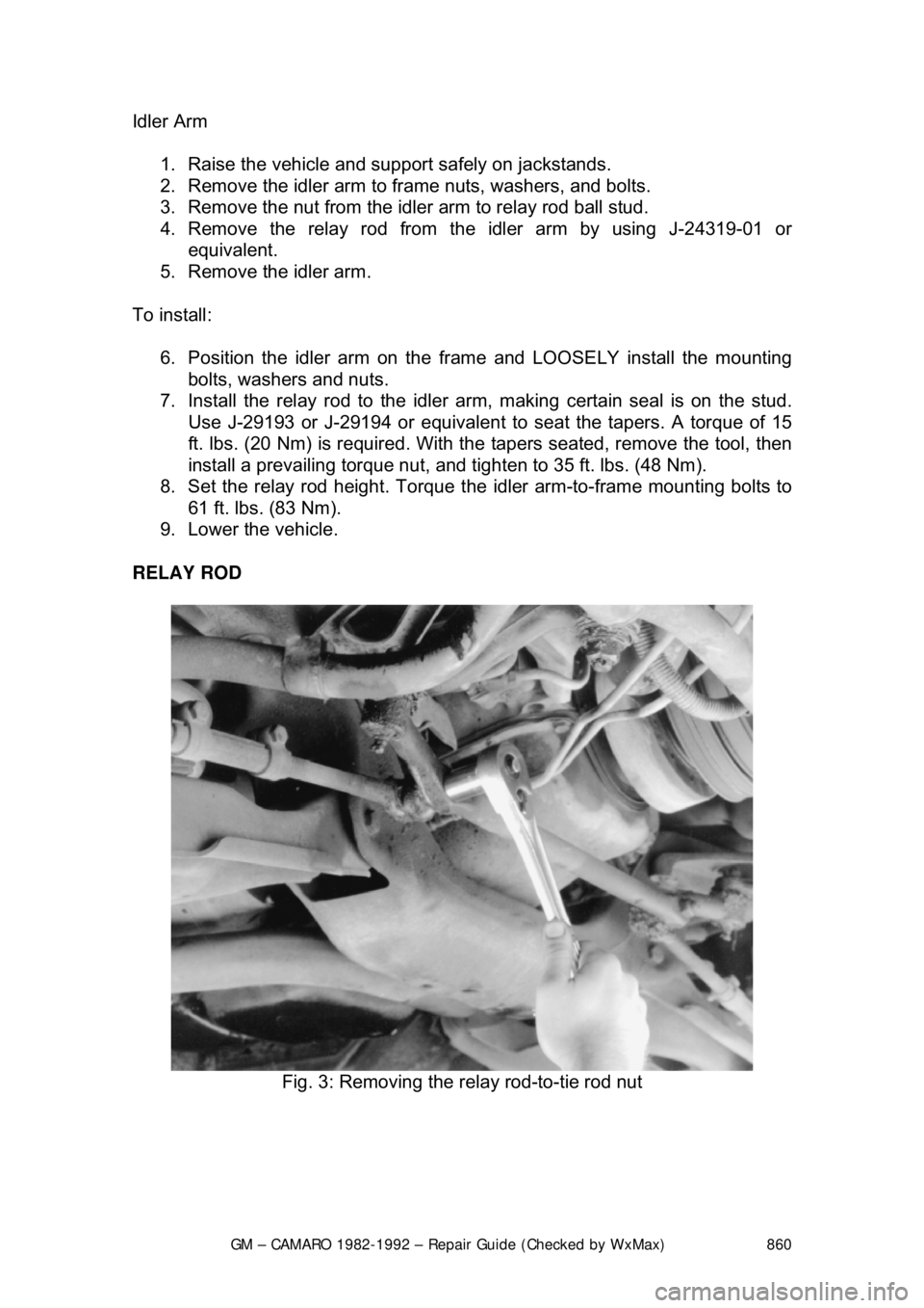
RELAY ROD
Fig. 3: Removing the relay rod-to-tie rod nut