1982 CHEVROLET CAMARO change wheel
[x] Cancel search: change wheelPage 49 of 875

GM – CAMARO 1982-1992 – Repair Guide (Checked by WxMax) 49
Upon release of the brake pedal, a spri
ng located inside the master cylinder
immediately returns the master cylinder pistons to the normal position. The
pistons contain check valv es and the master cylinder has compensating ports
drilled in it. These are uncovered as the pistons reach their normal position. The
piston check valves allow fluid to flow to ward the wheel cylinders or calipers as
the pistons withdraw. Then, as the return springs force the brake pads or shoes
into the released position, the excess fluid reservoir through the compensating
ports. It is during the time the pedal is in the released position that any fluid that
has leaked out of the syst em will be replaced through the compensating ports.
Dual circuit master cylinders employ tw o pistons, located one behind the other,
in the same cylinder. The primary pist on is actuated directly by mechanical
linkage from the brake peda l through the power booster. The secondary piston
is actuated by fluid tra pped between the two pistons. If a leak develops in front
of the secondary piston, it moves forward until it bottoms against the front of the
master cylinder, and the fluid trapped betw een the pistons will operate the rear
brakes. If the rear brakes develop a l eak, the primary piston will move forward
until direct contact with the secondary pi ston takes place, and it will force the
secondary piston to actuate the front brakes. In either case, the brake pedal
moves farther when the brakes are applied, and less braking power is available.
All dual circuit systems use a switch to wa rn the driver when only half of the
brake system is operational. This switch is usually located in a valve body which
is mounted on the firewall or the frame below the master cylinder. A hydraulic
piston receives pressure from both circui ts, each circuit's pressure being applied
to one end of the piston. When the pressures are in balance, the piston remains
stationary. When one circuit has a leak, however, the greater pressure in that
circuit during application of the brakes will push the piston to one side, closing
the switch and activating the brake warning light.
In disc brake systems, this valve body also contains a metering valve and, in
some cases, a proportioning valve. The metering valve keeps pressure fro\
m
traveling to the disc brakes on the front wheels until the brake shoes on the rear
wheels have contacted the drums, ensuri ng that the front brakes will never be
used alone. The proportioning va lve controls the pressure to the rear brakes to
lessen the chance of rear wheel lo ck-up during very hard braking.
Warning lights may be tested by depressi ng the brake pedal and holding it while
opening one of the wheel cyli nder bleeder screws. If this does not cause the
light to go on, substitute a new lamp , make continuity checks, and, finally,
replace the switch as necessary.
The hydraulic system may be checked for leaks by applying pressure to the
pedal gradually and steadily. If the pedal sinks very slowly to the floor, the
system has a leak. This is not to be conf used with a springy or spongy feel due
to the compression of air within the lin es. If the system leaks, there will be a
gradual change in the position of the pedal with a constant pressure.
Check for leaks along all lines and at wheel cylinders. If no external leaks are
apparent, the problem is inside the master cylinder.
Page 148 of 875

GM – CAMARO 1982-1992 – Repair Guide (Checked by WxMax) 148
ARMING SENSOR
The arming sensor is a protective switch
located in the power feed side of the
deployment loop. It is calibrated to clos e at low level velocity changes (lower
than the discriminating sens ors). This assures that the inflator module is
connected directly to the 36 volt output of the DERM or battery voltage feed
when either of the discrim inating sensors close.
DISCRIMINATING SENSORS
The discriminating sensors are wired in parallel on the ground side of the
deployment loop. These sensors are calib rated to close with velocity changes
which are severe enough to warrant deployment.
SIR COIL ASSEMBLY
The SIR coil assembly consists of two cu rrent carrying coils. They are attached
to the steering column and allow rotation of the steering wheel while maintaining
continuous contact of the deployment loop to the inflator module.
INFLATOR MODULES
Each inflator module consists of an inflat able bag and an inflator (a canister of
gas generating material with an initiati ng device). When the vehicle is in a
frontal crash of sufficient force, current flows through the deployment loops.
Current flowing through the initiator ignite s the material in the inflator module.
The gas produced from this reaction rapidly inflates the air bag.
Fig. 2: Forward discriminating se nsor location on 1990-1992 models
Page 219 of 875

GM – CAMARO 1982-1992 – Repair Guide (Checked by WxMax) 219
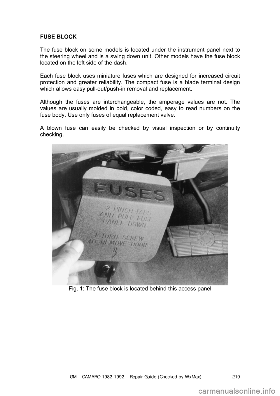
FUSE BLOCK
The fuse block on some models is loca
ted under the instrument panel next to
the steering wheel an d is a swing down unit. Other models have the fuse block
located on the left side of the dash.
Each fuse block uses miniature fuse s which are designed for increased circuit
protection and greater reliabi lity. The compact fuse is a blade terminal design
which allows easy pull-out/push- in removal and replacement.
Although the fuses are interchangeable , the amperage values are not. The
values are usually molded in bold, color coded, easy to read numbers on the
fuse body. Use only fuses of equal replacement valve.
A blown fuse can easily be checked by visual inspection or by continuity
checking.
Fig. 1: The fuse block is located behind this access panel
Page 287 of 875

GM – CAMARO 1982-1992 – Repair Guide (Checked by WxMax) 287
DRIVE TRAIN
MANUAL TRANSMISSION
UNDERSTANDING THE MANUAL TRANSMISSION
Because of the way an internal combus tion engine breathes, it can produce
torque (or twisting force) only withi n a narrow speed range. Most overhead
valve pushrod engines must turn at about 2500 rpm to produce their peak
torque. Often by 4500 rpm, they are prod ucing so little torque that continued
increases in engine speed produce no power increases.
The torque peak on overhead camshaft engines is, generally, much higher, but
much narrower.
The manual transmission and clutch are employed to vary the relationship
between engine RPM and the speed of the w heels so that adequate power can
be produced under all circumst ances. The clutch allows engine torque to be
applied to the transmission input shaft gradually, due to mechanical slippage.
The vehicle can, consequently, be star ted smoothly from a full stop.
The transmission changes the ratio between the rotating speeds of the engine
and the wheels by the use of gears. 4-speed or 5-speed transmissions are most
common. The lower gears al low full engine power to be applied to the rear
wheels during acceleration at low speeds.
The clutch driveplate is a thin disc, the center of which is splined to the
transmission input shaft. Both sides of the disc are covered with a layer of
material which is similar to brake li ning and which is capable of allowing
slippage without roughness or excessive noise.
The clutch cover is bolted to the engine flywheel and incorporates a diaphragm
spring which provides the pressure to engage the clutch. The cover also houses
the pressure plate. When the clutch pe dal is released, the driven disc is
sandwiched between the pressu re plate and the smooth surface of the flywheel,
thus forcing the disc to turn at th e same speed as the engine crankshaft.
The transmission contains a mainshaft which passes all the way through the
transmission, from the clutch to the dr iveshaft. This shaft is separated at one
point, so that front and rear portions can turn at different speeds.
Power is transmitted by a countershaft in the lower gears and reverse. The
gears of the countershaft mesh with gear s on the mainshaft, allowing power to
be carried from one to the other. Countershaft gears are often integral with that
shaft, while several of the mainshaft gea rs can either rotate independently of
the shaft or be locked to it. Shifting from one gear to the next causes one of the
gears to be freed from rotating with the shaft and locks another to it. Gears are
locked and unlocked by internal dog clutc hes which slide between the center of
the gear and the shaft. The forward gears us ually employ synchronizers; friction
Page 335 of 875

GM – CAMARO 1982-1992 – Repair Guide (Checked by WxMax) 335
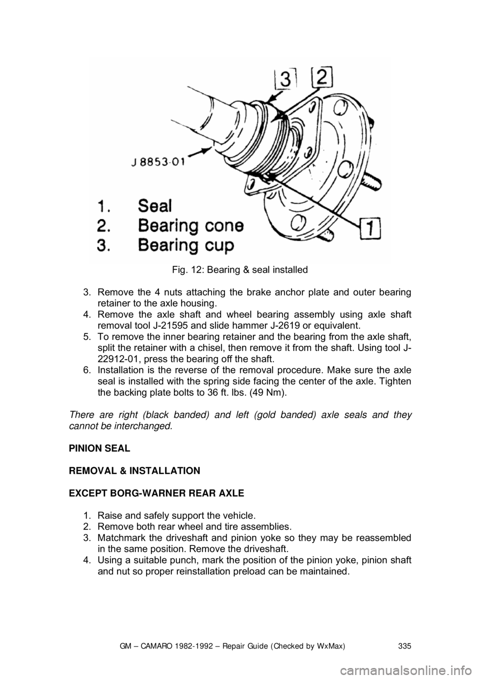
Fig. 12: Bearing & seal installed
3. Remove the 4 nuts attaching the brake anchor plate and outer bearing
retainer to the axle housing.
4. Remove the axle shaft and wheel bearing assembly using axle shaft removal tool J-21595 and slide hammer J-2619 or equivalent.
5. To remove the inner bearing retai ner and the bearing from the axle shaft,
split the retainer with a chisel, then re move it from the shaft. Using tool J-
22912-01, press the bearing off the shaft.
6. Installation is the reverse of the removal procedure. Make sure the axle
seal is installed with the spring side facing the center of the axle. Tighten
the backing plate bolts to 36 ft. lbs. (49 Nm).
There are right (black banded) and left (gold banded) axle seals and they
cannot be interchanged.
PINION SEAL
REMOVAL & INSTALLATION
EXCEPT BORG-WARNER REAR AXLE 1. Raise and safely support the vehicle.
2. Remove both rear wheel and tire assemblies.
3. Matchmark the driveshaft and pinion yoke so they may be reassembled
in the same position. Remove the driveshaft.
4. Using a suitable punch, mark the posit ion of the pinion yoke, pinion shaft
and nut so proper reinstallati on preload can be maintained.