1982 CHEVROLET CAMARO drain bolt
[x] Cancel search: drain boltPage 194 of 875

GM – CAMARO 1982-1992 – Repair Guide (Checked by WxMax) 194
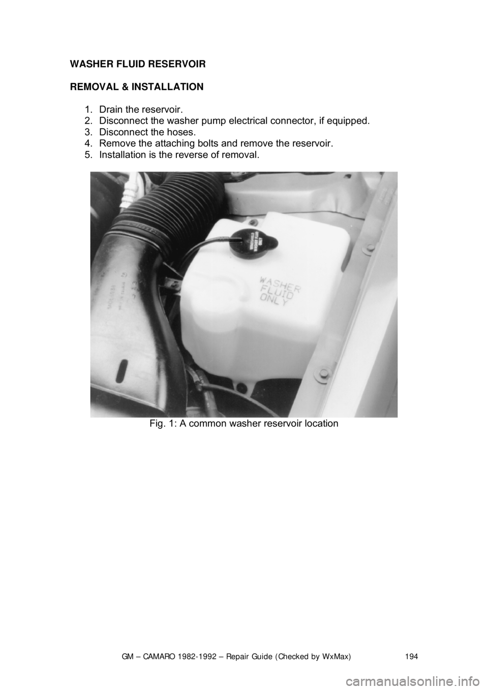
WASHER FLUID RESERVOIR
REMOVAL & INSTALLATION
1. Drain the reservoir.
2. Disconnect the washer pump elec trical connector, if equipped.
3. Disconnect the hoses.
4. Remove the attaching bolts and remove the reservoir.
5. Installation is the reverse of removal.
Fig. 1: A common washer reservoir location
Page 197 of 875

GM – CAMARO 1982-1992 – Repair Guide (Checked by WxMax) 197
PUMP IN WASHER TANK
1. Drain the washer tank and disconnect the wire connectors.
2. Disconnect and remove the reservoir
3. Remove the washer pump from the reservoir.
4. Installation is the reverse of t he removal procedure. Ensure pump is
pushed fully into the reservoir.
INSTRUMENTS AND SWITCHES
INSTRUMENT CLUSTER
REMOVAL & INSTALLATION
SPORT COUPE MODEL 1. Disconnect the negative battery cable.
2. Remove the instrument cluster bezel.
3. Remove the cluster attachment screws.
4. Pull the cluster out. Disconnect t he speedometer cable and electrical
connections.
5. Remove the cluster lens.
6. Install the cluster lens.
7. Connect the speedometer and electrical connections.
8. Push the cluster in.
9. Install the cluster attachment screws.
10. Install the instrument cluster bezel.
11. Connect the negative battery cable.
BERLINETTA MODEL 1. Disconnect the negative battery cable.
2. Remove the instrument cluster bezel.
3. Remove the 8 steering column tr im cover screws and trim cover.
4. Remove the right and left hand pod a ttaching screws at the bottom front
of each pod. Pull the pods rearward and disconnect the electrical
connection.
5. Remove the 5 cluster lens screws and lens.
6. Remove the 2 steering column bolts and lower the column.
7. Pull the instrument cluster rear ward and disconnect the electrical
connection. Remove the instrument cluster.
8. To install, position the inst rument cluster into place.
9. Connect the electrical connection and push the cluster forward.
10. Lift the column and install the 2 steering column bolts.
11. Install the lens and install the 5 cluster lens screws.
12. Connect the electrical connection to each pod and push forward. Install
the right and left hand pod attaching scr ews at the bottom front of each
pod. Pull the pods rearward and disconnect the electrical connection.
13. Install the trim cover and install th e 8 steering column trim cover screws.
14. Install the instrument cluster bezel.
Page 292 of 875

GM – CAMARO 1982-1992 – Repair Guide (Checked by WxMax) 292
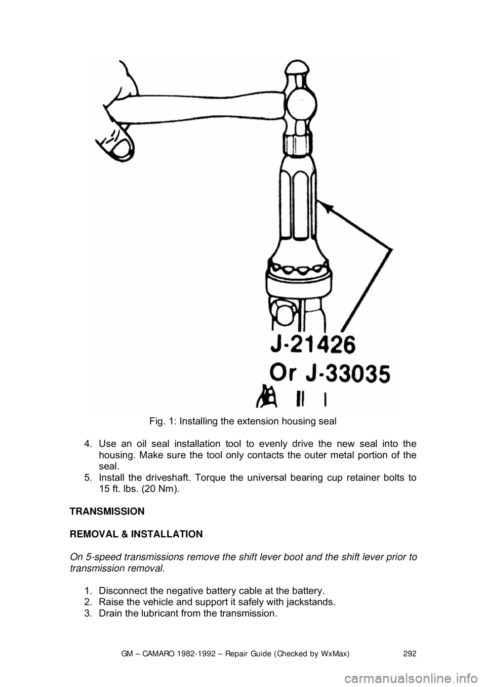
Fig. 1: Installing the extension housing seal
4. Use an oil seal installation tool to evenly drive the new seal into the
housing. Make sure the tool only cont acts the outer metal portion of the
seal.
5. Install the driveshaft. Torque the uni versal bearing cup retainer bolts to
15 ft. lbs. (20 Nm).
TRANSMISSION
REMOVAL & INSTALLATION
On 5-speed transmissions remove the shif t lever boot and the shift lever prior to
transmission removal.
1. Disconnect the negative batte ry cable at the battery.
2. Raise the vehicle and support it safely with jackstands.
3. Drain the lubricant from the transmission.
Page 320 of 875

GM – CAMARO 1982-1992 – Repair Guide (Checked by WxMax) 320
7. Unbolt the universal joint straps fr
om the pinion flange (use care to keep
the universal joint caps in place), lower and remove the driveshaft from
the vehicle. Place a transmission tailshaft plug or rag in place of the \
driveshaft to keep the transmission fluid from draining out.
8. Disconnect the catalytic converter support bracket at the transmission.
9. Disconnect the speedometer cable, electrical connectors and the shift
control cable from the transmission.
CAUTION - During the next step, rear spring force will cause the torque arm to
move toward the floor pan. When disconn ecting the arm from the transmission,
carefully place a piece of wood between the floor pan and the torque arm. This
will prevent possible personal injury and/or floor pan damage
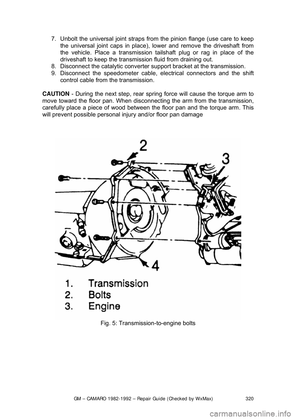
Fig. 5: Transmission-to-engine bolts
Page 328 of 875

GM – CAMARO 1982-1992 – Repair Guide (Checked by WxMax) 328
internal splines of each differential side
gear. As the side gears turn, so do the
axle shafts, and, since they are also connected, so do the wheels.
Each shaft passes through the side gear and is locked into place by either a C-
lock or flange plate bolted to the end of the axle housing with pressed on
bearings. As the name implies, the C-lock is a flat, C-shaped piece of metal that
fits into a groove at t he end of the shaft. A round pinion shaft is wedged in
between the end of the shafts. This pinion shaft prevents the shafts from sliding
inward and makes the C-locks functional by pushing them tightly against each
side gear. Removing this pini on shaft allows the shafts to slide inward making
the C-locks accessible for removal. Once the C-locks are removed, the axle
shafts can be pulled from the car.
The wheel end of each shaft is flanged and pressed into it are five wheel lug
bolts serving to hold on t he wheel. Each axle shaft is supported by an axle
bearing (wheel bearing) and oil seal located within the axle shaft housing just to
the outside of the br ake backing plate.
REMOVAL & INSTALLATION
EXCEPT BORG-WARNER REAR ASSEMBLY 1. Raise and support the vehicle safe ly. Remove the rear wheels and
drums or rotors.
2. Remove the carrier cover and drain t he gear oil into a suitable container.
Fig. 1: Clean the area around the bolts
Page 338 of 875

GM – CAMARO 1982-1992 – Repair Guide (Checked by WxMax) 338
seal preload. Turn the torque wrenc
h smoothly for several rotations and
record the amount of preload as the a ssembly is turning, not the initial
force required to start the assembly moving.
Preload is measured as the amount of torque required to turn the assembly.
5. Using a suitable tool to hold the pi nion yoke in place, remove the pinion
yoke nut and washer.
6. Place a suitable contai ner under the differential to catch any fluid that
may drain from the rear axle. Using a suitable tool, remove the pinion
flange.
7. Use a suitable tool to remove the pinion seal.
To install: 8. Inspect the seal surface of the pinion flange for tool marks, nicks or
damage and replace, as necessary. Examine the carrier bore and
remove any burrs that might cause leaks around the outside of the seal.
9. Install the seal 0.010 in. (0.2 5mm) below the flange surface using a
suitable seal installer.
10. Apply suitable seal lubricant to t he outer diameter of the pinion flange
and the sealing lip of the new seal.
11. Install the pinion flan ge on the drive pinion by taping with a soft hammer
until a few pinion threads projec t through the pinion flange.
12. Install the washer and pinion fla nge nut. While holding the pinion flange,
tighten the nut a little at a time and turn the drive pinion several
revolutions after each tightening, to set the bearing rollers. Check the
preload each time with a suitable inch pound to rque wrench until the
preload is 5 inch lbs. (0.6 Nm) more then the reading obtained during
disassembly.
13. Install the driveshaft.
14. Install the rear wheels and tires. Check and add the correct lubricant, as
necessary.
AXLE HOUSING
REMOVAL & INSTALLATION 1. Raise the vehicle and support it sa fely. Be sure that the rear axle
assembly is supported safely.
2. Disconnect shock absorbers from ax le. Remove the wheel assemblies.
3. Mark driveshaft and pinion flange, then disconnect driveshaft and support out of the way.
4. Remove brake line junction block bolt at axle housing. If necessary,
disconnect the brake lines at the junction block.
Page 340 of 875

GM – CAMARO 1982-1992 – Repair Guide (Checked by WxMax) 340
10. Install the brake line j
unction block bolt at the ax le housing. Connect any
brake lines that were disconnected.
11. Install and secure the driveshaft a ligning the match marks made earlier.
12. Connect the shock absorbers to the axle and install the wheel
assemblies.
13. Lower the vehicle and replace any lost rear axle fluid.
DIFFERENTIAL ASSEMBLY
REMOVAL & INSTALLATION 1. Raise and safely support the vehicle.
2. Place a suitable contai ner under the differential. Remove the carrier
cover and drain the gear oil.
3. Remove the drive axles.
4. Mark the differential bearing caps L and R to make sure they will be
reassembled in their original location.
5. Using a suitable tool, remove the di fferential carrier. Be careful not to
damage the gasket sealing surface wh en removing the unit. Place the
right and left bearing outer races of the side bearing assemblies and
shims in sets with the marked different ial bearings caps so they can be
reinstalled in their original positions.
To install: 6. Inspect the differential carrier housi ng for foreign material. Check the ring
and pinion for chipped teeth, exce ssive wear and scoring. Check the
carrier bearings visually and by feel . Clean the differential housing and
replace components, as necessary.
7. Install the differential carrier. C heck the carrier bearing preload along
with the ring and pinion backlash, then adjust, as necessary. Tighten the
differential bearing cap bolts to 55 ft. lbs. (75 Nm) except on Borg-
Warner rear axles which are ti ghtened to 40 ft. lbs. (54 Nm).
8. Install the axles.
9. Install the carrier cover using a new gasket. Tighten the carrier cover
bolts to 20 ft. lbs. (27 Nm). Add the proper type and quantity of gear oil to
axle assembly.
Page 362 of 875

GM – CAMARO 1982-1992 – Repair Guide (Checked by WxMax) 362
OIL PRESSURE SENDING UNIT
Replace the sending unit by disconnecting
the electrical connector and using a
special socket to remove it.
ENGINE
MECHANICAL ENGINE
REMOVAL & INSTALLATION
In the process of removing the engine, you will come across a number of steps
which call for the removal of a separ ate component or system, such as
"disconnect the exhaust system " or "remove the radiator." In most instances, a
detailed removal procedure can be found elsewhere in this repair guide.
It is virtually impossible to list each individual wire and hose which must be
disconnected, simply because so many different model and engine
combinations have been manufactured. Careful observation and common
sense are the best possible approaches to any repair procedure.
Removal and installation of the engine ca n be made easier if you follow these
basic points:
• If you have to drain any of the fl uids, use a suitable container.
• Always tag any wires or hoses and, if possible, the components they
came from before disconnecting them.
• Because there are so many bolts and fasteners involved, store and label
the retainers from com ponents separately in muffin pans, jars or coffee
cans. This will prevent conf usion during installation.
• After unbolting the transmission or trans axle, always make sure it is
properly supported.
• If it is necessary to disconnect t he air conditioning system, have this
service performed by a qualified tec hnician using a recovery/recycling
station. If the system does not have to be disconnected, unbolt the
compressor and set it aside.
• When unbolting the engine mounts, a lways make sure the engine is
properly supported. When removing t he engine, make sure that any
lifting devices are properly attached to the engine. It is recommended
that if your engine is supplied with lifting hooks, your lifting apparatus be
attached to them.
• Lift the engine from its compartment sl owly, checking that no hoses,
wires or other component s are still connected.
• After the engine is clear of the compar tment, place it on an engine stand
or workbench.
• After the engine has been removed, y ou can perform a partial or full
teardown of the engine using the procedur es outlined in this repair guide.