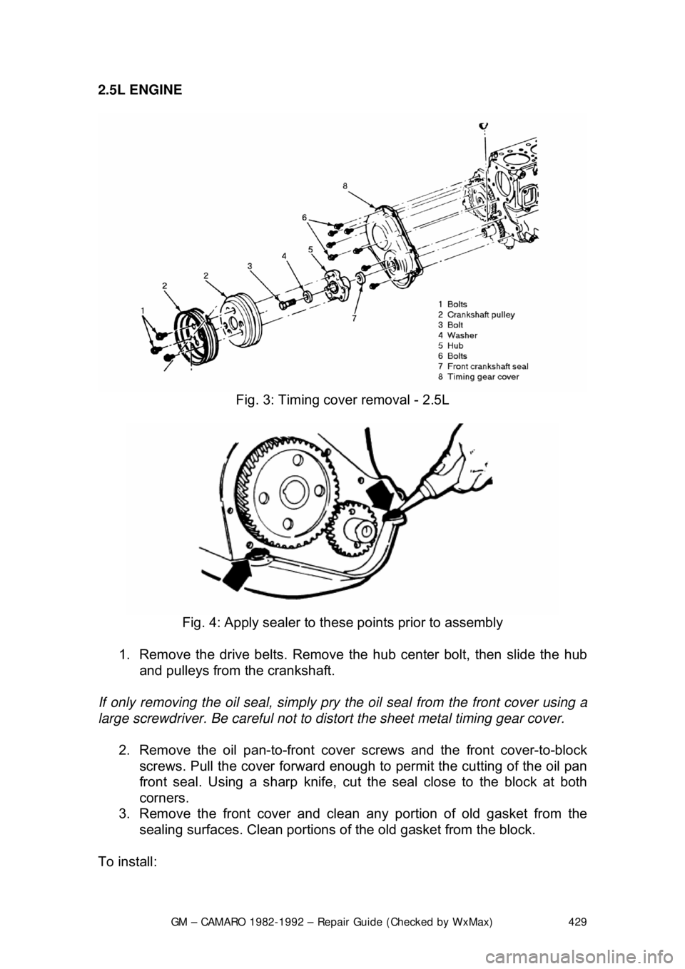
1982 CHEVROLET CAMARO timing belt
[x] Cancel search: timing beltPage 386 of 875

GM – CAMARO 1982-1992 – Repair Guide (Checked by WxMax) 386
FUEL INJECTION
1. Remove the air cleaner.
2. Drain the radiator.
3. Disconnect: a. Battery cables at the battery.
b. Upper radiator and heater hoses at the manifold.
c. Crankcase ventilation hoses as required.
d. Fuel line at the carburetor.
e. Accelerator linkage.
f. Vacuum hose at the distributor, if equipped.
g. Power brake hose at the car buretor base or manifold, if
applicable.
h. Temperature sending switch wires.
4. Remove the distributor cap and scribe the rotor position relative to the
distributor body, and engine.
5. Remove the distributor.
6. If applicable, remove the alternator upper bracket. As required, remove
the air cleaner bracket, and accelerator bellcrank.
7. Remove the manifold-to-head attachi ng bolts, then remove the manifold
and carburetor as an assembly.
8. Mark and disconnect all emission re lated items (e.g.: wiring, vacuum
hoses, etc.) which are connected to manifold mounted items.
9. If the manifold is to be replaced , transfer the carburetor (and mounting
studs), water outlet and thermostat (use a new gasket) heater hose
adapter, EGR valve (use new gasket) and, if applicable, TVS switch(s)
and the choke coil.
To install: 10. Before installing the manifold, thoroughly clean the gasket and sealing
surfaces of the cylinder heads and manifold.
11. Install the manifold end seals, folding the tabs if applicable, and the
manifold/head gaskets, using a s ealing compound around the water
passages.
Make sure that the new manifold gaskets match the old ones EXACTLY.
12. When installing the manifold, care should be taken not to dislocate the
end seals. It is helpful to use a pilo t in the distributor opening. Tighten the
manifold bolts to 30 ft. lbs. (40 Nm) for 5.0L or 20-25 ft. lbs. (27-34 Nm)
for 2.8L in the sequence illustrated.
13. Install the distributor with the rotor in its original location as indicated by
the scribe line. If the engi ne has been disturbed, refer to the previous
Distributor Removal and Installation procedure.
14. If applicable, install the alter nator upper bracket and adjust the belt
tension.
15. Connect all disconnected components at their original locations.
16. Fill the cooling system, start the engine, check for leaks and adjust the
ignition timing and carburetor idle speed and mixture.
Page 428 of 875

GM – CAMARO 1982-1992 – Repair Guide (Checked by WxMax) 428
1. Disconnect the battery ground c
able. Drain the cooling system.
2. Remove the fan shroud or the upper radiator support and drive belts.
Remove the fan and pulley from the water pump.
3. Remove the alternator upper and lower brackets, air brace with brackets,
and power steering lower bra cket (move it aside).
4. Remove the radiator lower hose and the heater hose from the water
pump. Remove the water pump bolts and the water pump.
5. If A/C equipped, remove the comp ressor and move aside. Remove the
compressor mounting bracket.
6. Remove the damper pulley retain ing bolt and the damper pulley.
7. Remove the timing gear cover bolts and the timing gear cover.
With the timing gear cover removed, use a large screwdriver to pry the oil seal
from the cover. To install the new oil se al, lubricate it with engine oil and drive it
into place.
To install: 8. Prepare the mating surfaces for reinst allation of the timing gear cover.
Coat the new gasket with RTV sealer.
9. Install the timing gear cover and timing gear cover bolts. Torque the
cover bolts to specifications:
• V6 engines (M8 x 1.25 bolts): 13-22 ft. lbs. (18-30 Nm)
• V6 engines (M10 x 1.5 bolts): 20-35 ft. lbs. (27-48 Nm)
• V8 engines (all bolts): 69-130 inch lbs. (8-14 Nm)
10. Install the damper pulley by pulli ng the damper onto the crankshaft. Use
tool J-23523 or equivalent. Install t he damper pulley retaining bolt and
torque bolts to 67-85 ft lbs. (90-110 Nm).
11. If A/C equipped, install the compressor mounting bracket and
compressor.
12. Install the water pump and the water pump bolts.
13. Install the radiator lower hose and the heater hose to the water pump.
14. Install the alternator upper and lower brackets, air brace with brackets
and the power steering lower bracket.
15. Install the fan and pull ey to the water pump. Inst all the fan shroud or the
upper radiator support and drive belts and adjust.
16. Connect the battery ground cable.
17. Fill the cooling syst em, start the engine and check for leaks.
Page 429 of 875

GM – CAMARO 1982-1992 – Repair Guide (Checked by WxMax) 429
2.5L ENGINE
Fig. 3: Timing cover removal - 2.5L
Fig. 4: Apply sealer to t hese points prior to assembly
1. Remove the drive belts. Remove the hub center bolt, then slide the hub
and pulleys from the crankshaft.
If only removing the oil seal, simply pry t he oil seal from the front cover using a
large screwdriver. Be careful not to di stort the sheet metal timing gear cover.
2. Remove the oil pan-to-front cove r screws and the front cover-to-block
screws. Pull the cover forward enough to permit the cutting of the oil pan
front seal. Using a sharp knife, cut the seal close to the block at both
corners.
3. Remove the front cover and clean any portion of old gasket from the
sealing surfaces. Clean portions of the old gasket from the block.
To install:
Page 430 of 875

GM – CAMARO 1982-1992 – Repair Guide (Checked by WxMax) 430
4. Use a new front oil pan gasket, cut
the tabs from the gasket. Replace the
crankshaft oil seal.
5. Place RTV sealer in the corners of the new oil pan gasket and the new
timing gear cover gasket.
6. Install the front cove r and install the oil pan-to -front cover screws and the
front cover-to-block screws. Torque scr ews to 90 inch lbs. (10 Nm).
7. Install the hub and pulle ys onto the crankshaft. Install the hub center bolt
and torque to 162 ft lbs. (220 Nm).
8. Install the drive belts and adjust.
TIMING GEAR COVER OIL SEAL REPLACEMENT
Fig. 5: Installing the oil seal with the cover installed
Page 441 of 875

GM – CAMARO 1982-1992 – Repair Guide (Checked by WxMax) 441
2. Remove the fan, driv
e belts and water pump pul ley. Remove the valve
cover. Loosen the rocker arms and pivot them, then remove the
pushrods.
3. Remove the oil pump driveshaft and gear assembly. This is located
under a small plate secured by two bol ts near the oil filter. Remove the
spark plugs.
4. Mark the position of the distribut or rotor, housing, and engine block.
Remove the distributor.
5. Remove the valve lifters. They are located behind the pushrod cover.
6. Remove the timing gear cover.
7. Insert a screwdriver through the holes in the ti ming gear and remove the
2 camshaft thrust plate screws.
8. Pull the camshaft and gear assembly out through the front of the engine
block.
When removing the camshaft, be careful not to damage the camshaft bearings.
9. If the camshaft is to be removed from the timing gear, place the assembly in an arbor press and s eparate. CAUTION When removing the
timing gear from the camshaft, the thrust plate must be positioned so that
the woodruff key does not damage it.
To install: 10. To install the timing gear to the camshaft, press the assembly together
and measure the end clearance. T here should be 0.0015-0.0050 in.
(0.038-0.127mm) between the thrust plate and the camshaft.
If the clearance is less than 0.0015 in. (0 .038mm), replace the spacer ring; if
more than 0.0050 in. (0.127mm), replace the thrust ring.
11. Lubricate the camshaft, bearings, and lifters. Slide the camshaft
assembly into the engine and align the timing marks of the camshaft gear
and crankshaft gear.
12. Complete the installation by reversing the removal procedure.
V6 AND V8 ENGINES 1. Remove the engine from the vehicl e or remove all components from the
front of the engine (radi ator, grille, etc.).
2. Remove the timing gear cover and chain.
3. Mark the distributor rotor, housi ng and engine block, then remove the
distributor. Remove the fuel pump and fuel pump pushrod on carbureted
engines.
4. Remove the intake manifold and valve covers. Loosen the rocker arms
and pivot out of way. Remove the pushrods and valve lifters.
5. Remove the oil pump drive.
6. Slide the camshaft toward the front of the engine (be careful not to
damage the camshaft bearings).
Page 491 of 875

GM – CAMARO 1982-1992 – Repair Guide (Checked by WxMax) 491
The first step for any assembly job is
to have a clean area in which to work.
Next, thoroughly clean all of the parts and components that are to be
assembled. Finally, place all of the co mponents onto a suitable work space and,
if necessary, arrange the parts to their respective positions.
1. Lightly lubricate the valve stems and insert all of the valves into the
cylinder head. If possible, maintain their original locations.
2. If equipped, install any valve spring shims which were removed.
3. If equipped, install the new valve seal s, keeping the following in mind:
• If the valve seal presses over the guide, lightly lubricate the outer
guide surfaces.
• If the seal is an O-ring type, it is installed just after compressing
the spring but before the valve locks.
4. Place the valve spring and retainer over the stem.
5. Position the spring compressor tool and compress the spring.
6. Assemble the valv e locks to the stem.
7. Relieve the spring pressure slowly and insure that neither valve lock
becomes dislodged by the retainer.
8. Remove the spring compressor tool.
9. Repeat Steps 2 through 8 until all of the springs have been installed.
ENGINE BLOCK
GENERAL INFORMATION
A thorough overhaul or rebuild of an engine block would include replacing the
pistons, rings, bearings, timing belt/chai n assembly and oil pump. For OHV
engines also include a new camshaft and lifters. The block would then have the
cylinders bored and honed oversize (or if using removable cylinder sleeves,
new sleeves installed) and the cranksha ft would be cut undersize to provide
new wearing surfaces and per fect clearances. However, your particular engine
may not have everything worn out. What if only the piston rings have worn out
and the clearances on everything else are still within factory specifications?
Well, you could just replace the rings and put it back together, but this would be
a very rare example. Chances are, if one component in your engine is worn,
other components are sure to follow, and soon. At the very least, you should
always replace the rings, bearings and oil pump. This is what is commonly
called a "freshen up".
CYLINDER RIDGE REMOVAL
Because the top piston ring does not travel to the very top of the cylinder, a
ridge is built up between the end of the trav el and the top of the cylinder bore.
Pushing the piston and connecting rod assembly past the ridge can be difficult,
and damage to the piston ring lands could occur. If the ridge is not removed
before installing a new piston or not re moved at all, piston ring breakage and
piston damage may occur.