1982 CHEVROLET CAMARO reset
[x] Cancel search: resetPage 131 of 875

GM – CAMARO 1982-1992 – Repair Guide (Checked by WxMax) 131
•
Circuit Breaker - a circuit breaker is basically a self-repairing fuse. It will
open the circuit in the same fashio n as a fuse, but when the surge
subsides, the circuit breaker can be reset and does not need
replacement.
• Fusible Link - a fusible link (fuse link or main link) is a short length of
special, high temperatur e insulated wire that acts as a fuse. When an
excessive electrical current passes th rough a fusible link, the thin gauge
wire inside the link melt s, creating an intentional open to protect the
circuit. To repair the circuit, the link must be replaced. Some newer type
fusible links are housed in plug-in modules, which are simply replaced
like a fuse, while older type fusible lin ks must be cut and spliced if they
melt. Since this link is very early in the electrical path, it's the first place to
look if nothing on the vehicle works, yet the battery seems to be charged
and is properly connected.
CAUTION - Always replace fuses, circ uit breakers and fusible links with
identically rated component s. Under no circumstances should a component of
higher or lower amperage rating be substituted.
SWITCHES & RELAYS
Switches are used in electrical circuits to control the passage of current. The
most common use is to open and close circuits between the battery and the
various electric devices in the system. Switches are rated according to the
amount of amperage they c an handle. If a sufficient amperage rated switch is
not used in a circuit, the switch could overload and cause damage.
Fig. 2: The underhood fuse and relay panel usually contains fuses, relays,
flashers and fusible links
Page 145 of 875

GM – CAMARO 1982-1992 – Repair Guide (Checked by WxMax) 145
When the battery cable(s) are reconnecte
d (negative cable last), be sure to
check that your lights, windshield wipers and other electrically operated safety
components are all working correctly. If your vehicle contains an Electronically
Tuned Radio (ETR), don't forget to also reset your radio stations. Ditto for the
clock.
Page 199 of 875

GM – CAMARO 1982-1992 – Repair Guide (Checked by WxMax) 199
Federal law requires that the
odometer in any replacement
speedometer/odometer must r egister the same mileage as that registered on
the removed speedometer/odometer. Service replacement
speedometer/odometers and odometer modul es with the mileage preset to
actual vehicle mileage are available through the dealer. In nearly all cases, the
mileage continues to accumu late in the odometer memory even if the odometer
does not display mileage. Th is mileage can usually be verified by the dealer.
Contact the dealer for instructi ons to receive a replacement
speedometer/odometer with pres et mileage. If the actual vehicle mileage cannot
be verified, the dealer will supply a spe edometer/odometer with a display set to
zero miles. In addition, an odometer mileage sticker is supplied with the
replacement odometer. The sticker must display the estimated vehicle mileage
and is to be affixed to the driver's door.
REMOVAL & INSTALLATION 1. The gauges can be removed from the cluster assembly by: a. Removing the cluster lens.
b. Removing the printed circuit board from the back of the cluster.
c. Removing the gauge attaching screws.
2. Installation is the reverse of removal.
SPEEDOMETER CABLE
REMOVAL & INSTALLATION 1. Disconnect the negative batte ry cable at the battery.
2. On models without cruise control, disconnect the speedometer cable
strap at the power brake booster. On models with cruise control,
disconnect the speedometer cable at the cruise control transducer.
3. Remove the instrument cluster trim plate.
4. Remove the instrument cluster a ttaching screws and pull the cluster out
far enough to gain access to the r ear of the speedometer head.
5. Reach beneath the c able connection at the speedometer head, push in
on the cable retaining spring, and disconnect the cable from the
speedometer.
6. Slide the old cable ou t of the speedometer cable casing. If the cable is
broken, remove the cable from both ends of the casing. Using a short
piece of the old cable to fit t he speedometer connection, turn the
speedometer to increase the speed i ndicated on the dial and check for
any binding during rotation. If binding is noted, the speedometer must be
removed for repair or replacement. Check the entire cable casing for
extreme bends, chafing, breaks, et c., and replace if necessary.
To install: 7. Wipe the cable clean us ing a lint free cloth.
8. If the old casing is to be reused, flush the casing with petroleum spirits
and blow dry with compressed air.
Page 582 of 875

GM – CAMARO 1982-1992 – Repair Guide (Checked by WxMax) 582
REMOVAL & INSTALLATION
On some models it may be necessary
to remove the air inlet assembly.
1. Disconnect the negative battery cable. Disconnect the IAC valve
electrical wiring.
2. Remove the IAC valve by performing the following: a. On thread-mounted units, use a 1
1/4 inch (32mm) wrench.
b. On flange-mounted units, remove the mounting screw assemblies.
3. Remove the IAC valve ga sket or O-ring and discard.
To install: 4. Clean the mounting surfaces by performing the following:
a. If servicing a thread-mounted valve, remove the old gasket material from the surf ace of the throttle body to ensure proper
sealing of the new gasket.
b. If servicing a flange-mounted valve, clean the IAC valve surfaces on the throttle body to assure pr oper seal of the new O-ring and
contact of the IAC valve flange.
5. If installing a new IAC valve, meas ure the distance between the tip of the
IAC valve pintle and the mounting flange. If the distance is greater than
1.102 inch (28mm), use finger pressure to slowly retract the pintle. The
force required to retract the pintle of a new valve will not cause damage
to the valve. If reinstalling the origin al IAC valve, do not attempt to adjust
the pintle in this manner.
6. Install the IAC valve into the thro ttle body by performing the following:
a. With thread-mounted valves, in stall with a new gasket. Using a
1
1/4 inch (32mm) wrench, tighten to 13 ft. lbs. (18 Nm).
b. With flange-mounted valves, lubricate a new O-ring with
transmission fluid and install on the IAC valve. Install the IAC
valve to the throttle body. Inst all the mounting screws using a
suitable thread locking compound. Tight en to 28 inch lbs. (3 Nm).
7. Connect the IAC valve electrical wiring.
8. Connect the negative battery cable.
9. No physical adjustment of the IAC valve assembly is required after installation. Reset the IAC valve pintle position by performing the
following:
a. Depress the accelerator pedal slightly.
b. Start the engine and run for 5 seconds.
c. Turn the ignition switch to the OFF position for 10 seconds.
d. Restart the engine and check for proper idle operation.
Page 596 of 875

GM – CAMARO 1982-1992 – Repair Guide (Checked by WxMax) 596
recommended to have a qualified technici
an perform any further testing, if
needed.
FIELD SERVICE MODE
On fuel injected models, if the ALDL terminal B is grounded to terminal A with
the engine running, the system enters the Field Service Mode. In this mode, the
MIL will indicate whether the system is operating in open loop or closed loop.
If working in open loop, t he MIL will flash rapidly 2
1/2 times per second. In
closed loop, the flash rate slows to once per second. Additionally, if the system
is running lean in closed loop, the lamp will be off most of the cycle. A rich
condition in closed loop will cause the lamp to remain lit for most of the one
second cycle.
When operating in the Field Service M ode, additional codes cannot be stored
by the ECM. The closed loop timer is bypassed in this mode.
CLEARING CODES
Stored fault codes may be erased from me mory at any time by removing power
from the ECM for at least 30 seconds. It may be necessary to clear stored
codes during diagnosis to check for any re currence during a test drive, but the
stored should be written dow n when retrieved. The codes may still be required
for subsequent troubleshooting. Whenever a repair is complete, the stored
codes must be erased and the vehicle te st driven to confirm correct operation
and repair.
The ignition switch must be OFF any ti me power is disconnected or restored to
the ECM. Severe damage may result if this precaution is not observed.
Depending on the electric di stribution of the particular vehicle, power to the
ECM may be disconnected by removing the ECM fuse in the fusebox or
disconnecting the inline EC M power lead at the positive battery terminal.
Disconnecting the negative battery cable to clear codes will achieve the desired
result, but this will also clear other me mory data in the vehicle such as radio
presets or seat memory.
Page 672 of 875

GM – CAMARO 1982-1992 – Repair Guide (Checked by WxMax) 672
ROCHESTER E4ME AND E4MC
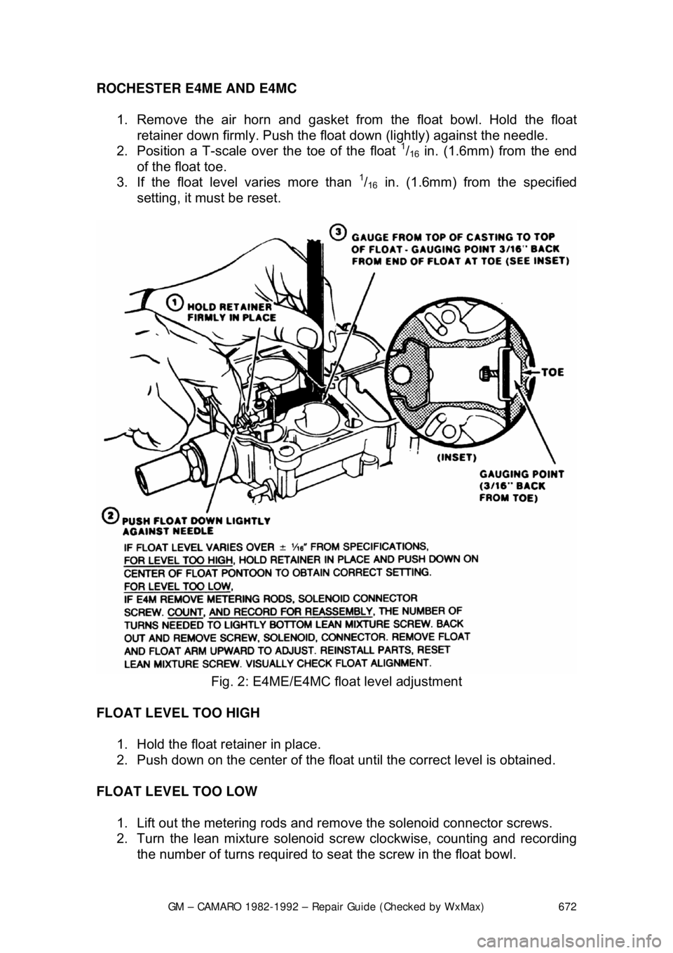
1. Remove the air horn and gasket from the float bowl. Hold the float retainer down firmly. Push the float down (lightly) against the needle.
2. Position a T-scale ov er the toe of the float
1/16 in. (1.6mm) from the end
of the float toe.
3. If the float level varies more than
1/16 in. (1.6mm) from the specified
setting, it must be reset.
Fig. 2: E4ME/E4MC float level adjustment
FLOAT LEVEL TOO HIGH 1. Hold the float retainer in place.
2. Push down on the center of the float until the correct level is obtained.
FLOAT LEVEL TOO LOW 1. Lift out the metering rods and remo ve the solenoid connector screws.
2. Turn the lean mixture solenoid screw clockwise, counting and recording
the number of turns required to seat the screw in the float bowl.
Page 722 of 875

GM – CAMARO 1982-1992 – Repair Guide (Checked by WxMax) 722
FUEL PRESSURE REGULATOR
REMOVAL & INSTALLATION
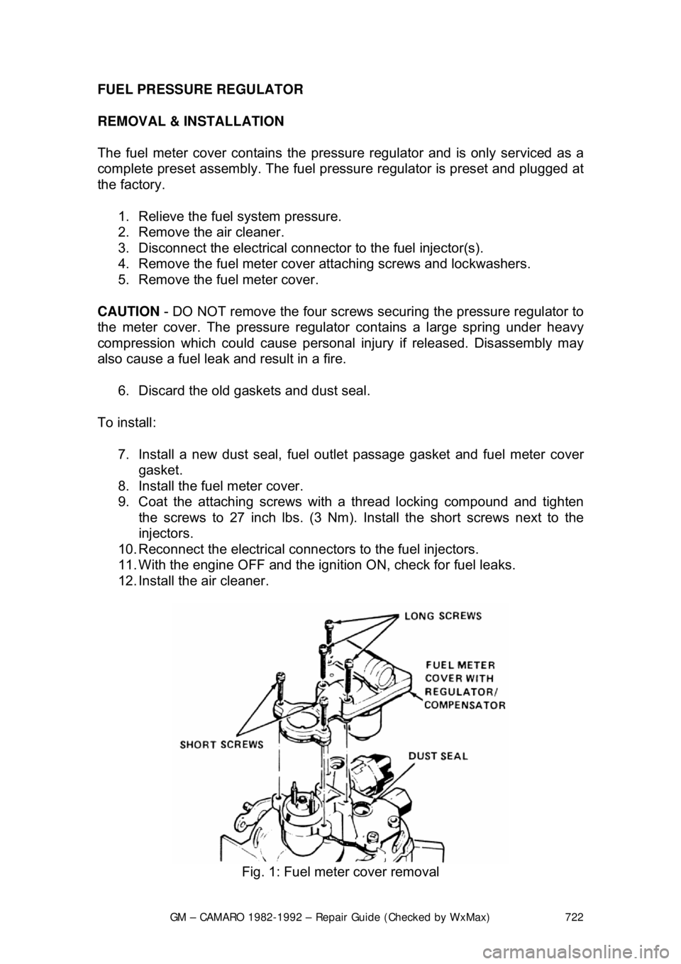
The fuel meter cover contains the pressu
re regulator and is only serviced as a
complete preset assembly. The fuel pressu re regulator is preset and plugged at
the factory.
1. Relieve the fuel system pressure.
2. Remove the air cleaner.
3. Disconnect the electrical connec tor to the fuel injector(s).
4. Remove the fuel meter cover attaching screws and lockwashers.
5. Remove the fuel meter cover.
CAUTION - DO NOT remove the four screws se curing the pressure regulator to
the meter cover. The pressure regulat or contains a large spring under heavy
compression which could cause personal injury if released. Disassembly may
also cause a fuel leak and result in a fire.
6. Discard the old gaskets and dust seal.
To install: 7. Install a new dust seal, fuel outlet passage gasket and fuel meter cover\
gasket.
8. Install the fuel meter cover.
9. Coat the attaching screws with a thread locking compound and tighten the screws to 27 inch lbs. (3 Nm). Install the short screws next to the
injectors.
10. Reconnect the electrical connec tors to the fuel injectors.
11. With the engine OFF and the igniti on ON, check for fuel leaks.
12. Install the air cleaner.
Fig. 1: Fuel meter cover removal
Page 724 of 875

GM – CAMARO 1982-1992 – Repair Guide (Checked by WxMax) 724
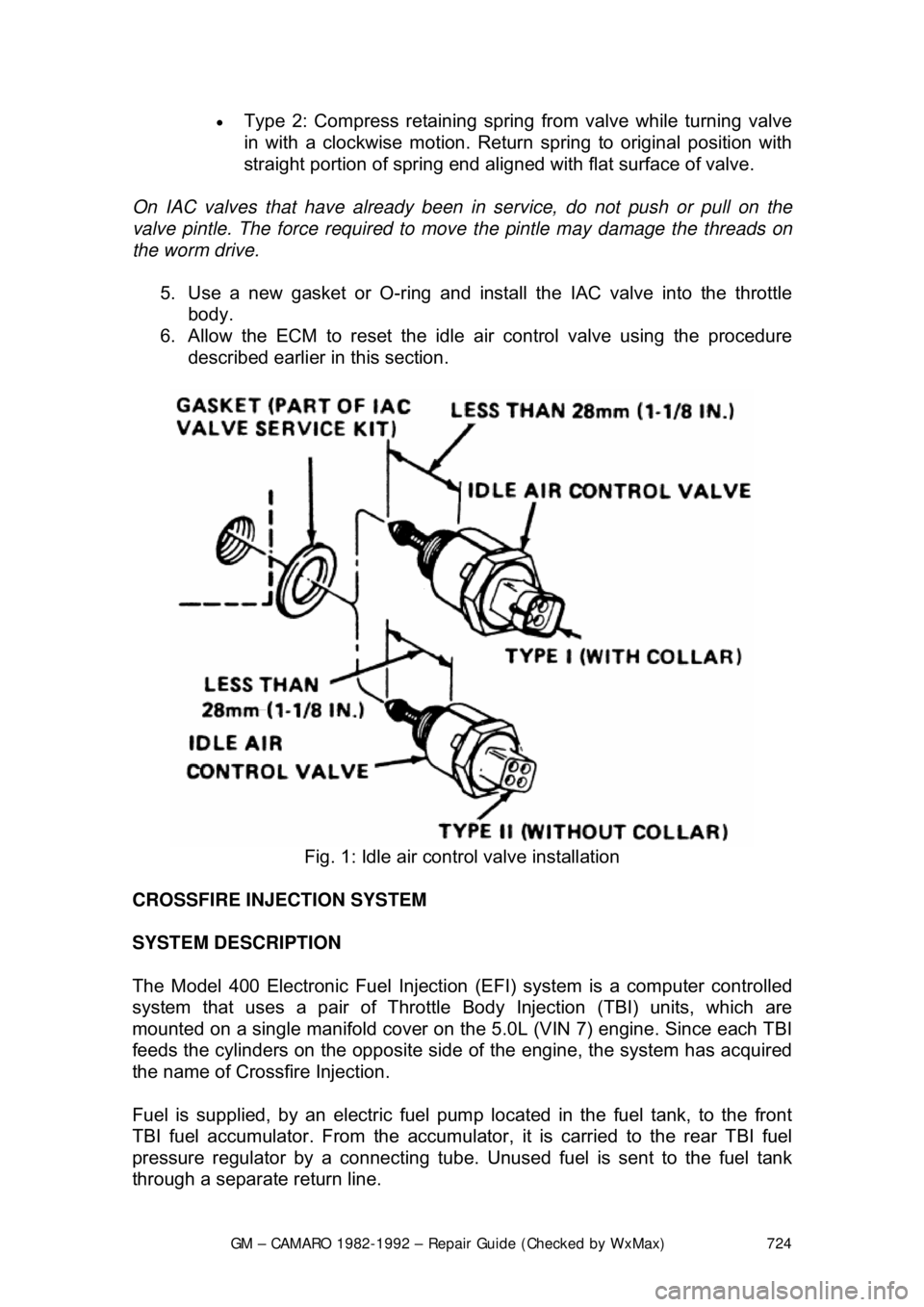
•
Type 2: Compress retaining spring from valve while turning valve
in with a clockwise motion. Return spring to original position with
straight portion of spring end aligned with flat surface of valve.
On IAC valves that have already been in service, do not push or pull on the
valve pintle. The force required to move the pintle may damage the threads on
the worm drive.
5. Use a new gasket or O-ring and install the IAC valve into the throttle body.
6. Allow the ECM to reset the idle air control valve using the procedure
described earlier in this section.
Fig. 1: Idle air control valve installation
CROSSFIRE INJECTION SYSTEM
SYSTEM DESCRIPTION
The Model 400 Electronic Fuel Injection (EFI) system is a computer controlled
system that uses a pair of Throttle Body Injection (TBI) units, which are
mounted on a single manifold cover on t he 5.0L (VIN 7) engine. Since each TBI
feeds the cylinders on the opposite side of the engine, the system has acquired
the name of Crossf ire Injection.
Fuel is supplied, by an electric fuel pum p located in the fuel tank, to the front
TBI fuel accumulator. From the accumulator, it is carried to the rear TBI fuel
pressure regulator by a c onnecting tube. Unused fuel is sent to the fuel tank
through a separate return line.