1982 CHEVROLET CAMARO tire size
[x] Cancel search: tire sizePage 87 of 875

GM – CAMARO 1982-1992 – Repair Guide (Checked by WxMax) 87
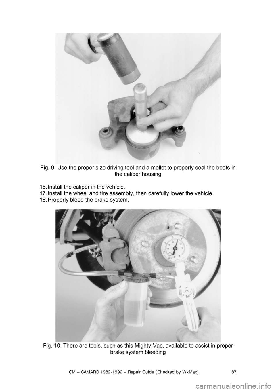
Fig. 9: Use the proper size driving tool and a mallet to properly seal the boots in
the caliper housing
16. Install the caliper in the vehicle.
17. Install the wheel and tire assembly , then carefully lower the vehicle.
18. Properly bleed t he brake system.
Fig. 10: There are tools, such as this Mighty-Vac, available to assist in proper
brake system bleeding
Page 132 of 875

GM – CAMARO 1982-1992 – Repair Guide (Checked by WxMax) 132
Some electrical components which require
a large amount of current to operate
use a special switch called a relay. Sinc e these circuits carry a large amount of
current, the thickness of the wire in the ci rcuit is also greater. If this large wire
were connected from the load to the c ontrol switch, the switch would have to
carry the high amperage load and the fair ing or dash would be twice as large to
accommodate the increased size of t he wiring harness. To prevent these
problems, a relay is used.
Relays are composed of a coil and a se t of contacts. When the coil has a
current passed though it, a magnetic fiel d is formed and this field causes the
contacts to move together, completing the circuit. Most relays are normally
open, preventing current from passing thr ough the circuit, but they can take any
electrical form depending on th e job they are intended to do. Relays can be
considered "remote control switches." They allow a smaller current to operate
devices that require higher amperages. W hen a small current operates the coil,
a larger current is allo wed to pass by the contacts. Some common circuits
which may use relays are the horn, headlight s, starter, electric fuel pump and
other high draw circuits.
Fig. 3: Relays are composed of a coil and a switch. These two components are
linked together so that w hen one operates, the other operat es at the same time.
The large wires in the circuit are connect ed from the battery to one side of the
relay switch (B+) and from the opposite side of the re lay switch to the load
(component). Smaller wires are connected from the relay coil to the control
switch for the circuit and from the opposite side of the relay coil to ground
LOAD
Every electrical circuit must include a "load" (something to use the electricity
coming from the source). Without this l oad, the battery would attempt to deliver
its entire power supply from one pole to another. This is called a "short circuit."
All this electricity would take a short cut to ground and cause a great amount of
damage to other components in the circui t by developing a tremendous amount
of heat. This condition could develop suffici ent heat to melt the insulation on all
the surrounding wires and reduce a multiple wire cable to a lump of plastic and
copper.
Page 499 of 875

GM – CAMARO 1982-1992 – Repair Guide (Checked by WxMax) 499
then you have wrist pin bushings in the rods. There should not be any
excessive play between the wrist pin
and the rod bushing. Normal clearance for
the wrist pin is approx. 0.001-0.002 in. (0.025mm-0.051mm).
Fig. 4: Measure the piston's outer diam eter, perpendicular to the wrist pin, with
a micrometer
Use a micrometer and measure the diamet er of the piston, perpendicular to the
wrist pin, on the skirt. Com pare the reading to its original cylinder measurement
obtained earlier. The diffe rence between the two readings is the piston-to-wall
clearance. If the clearance is within specif ications, the piston may be used as is.
If the piston is out of specification, but the bore is not, you will need a new
piston. If both are out of specificati on, you will need the cylinder rebored and
oversize pistons installed. Generally if two or more pistons/bores are out of
specification, it is best to rebore the entire block and purchase a complete set of
oversize pistons.
CONNECTING ROD
You should have the connecting rod chec ked for straightness at a machine
shop. If the connecting rod is bent, it will unevenly wear the bearing and piston,
as well as place greater stress on these components. Any bent or twisted
connecting rods must be replaced. If the rods are straight and the wrist pin
clearance is within specifications, t hen only the bearing end of the rod need be
checked. Place the connecting rod into a vi ce, with the bearing inserts in place,
install the cap to the rod and torque t he fasteners to specifications. Use a
telescoping gauge and carefully measure t he inside diameter of the bearings.
Compare this reading to the rods or iginal crankshaft journal diameter
measurement. The difference is the oil clearance. If the oil clearance is not
Page 503 of 875

GM – CAMARO 1982-1992 – Repair Guide (Checked by WxMax) 503
Mount the engine block into the engine
stand and wash it one last time using
water and detergent (dishwashing deter gent works well). While washing it,
scrub the cylinder bores with a soft bristl e brush and thoroughly clean all of the
oil passages. Completely dry the engin e and spray the entire assembly down
with an anti-rust solution such as WD-40 or similar product. Take a clean lint-
free rag and wipe up any excess anti-rust solution from the bores, bearing
saddles, etc. Repeat the final cleaning process on the crankshaft. Replace any
freeze or oil galley plugs which we re removed during disassembly.
CRANKSHAFT 1. Remove the main bearing inserts from the block and bearing caps.
2. If the crankshaft main bearing journal s have been refinished to a definite
undersize, install the correct undersize bearing. Be sure that the bearing
inserts and bearing bores are clean. Fo reign material under inserts will
distort bearing and cause failure.
3. Place the upper main bearing inse rts in bores with tang in slot.
The oil holes in the beari ng inserts must be aligned with the oil holes in the
cylinder block.
4. Install the lower main bearing inserts in bearing caps.
5. Clean the mating surfaces of block and rear main bearing cap.
6. Carefully lower the crankshaft into place. Be careful not to damage
bearing surfaces.
7. Check the clearance of each main bearing by using the following
procedure: a. Place a piece of Plastigage® or its equivalent, on bearing surface
across full width of bearing cap and about
1/4 in. off center.
Page 813 of 875

GM – CAMARO 1982-1992 – Repair Guide (Checked by WxMax) 813
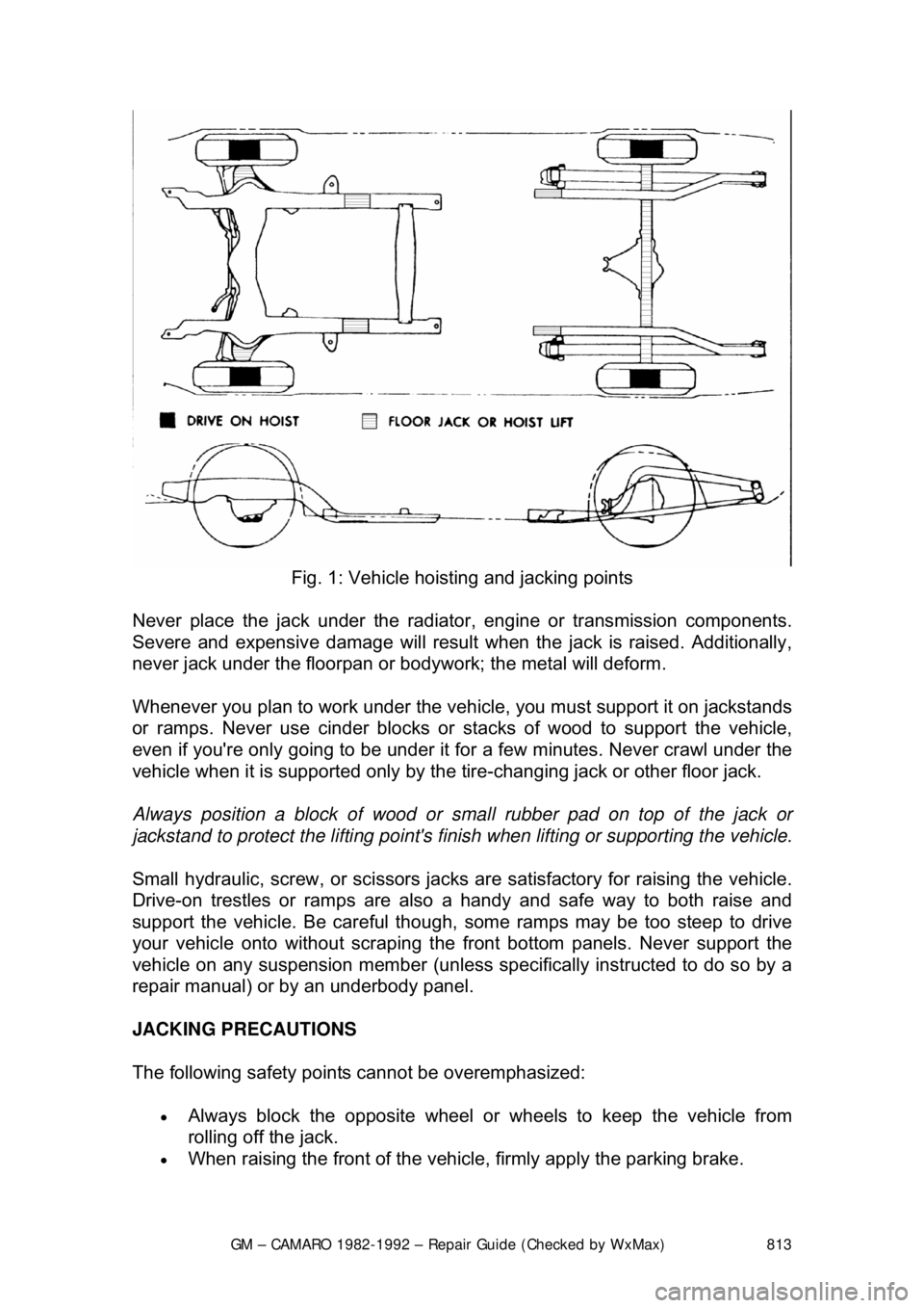
Fig. 1: Vehicle hoisting and jacking points
Never place the jack under the radiator , engine or transmission components.
Severe and expensive damage wil l result when the jack is raised. Additionally,
never jack under the floorpan or body work; the metal will deform.
Whenever you plan to work under the v ehicle, you must support it on jackstands
or ramps. Never use cinder blocks or st acks of wood to support the vehicle,
even if you're only going to be under it for a few minutes. Never crawl under the
vehicle when it is supported only by the tire-changing jack or other floor jack.
Always position a block of wood or smal l rubber pad on top of the jack or
jackstand to protect the lifting point's finish when lifting or supporting the vehicle.
Small hydraulic, screw, or sci ssors jacks are satisfactory for raising the vehicle.
Drive-on trestles or ramps are also a handy and safe way to both raise and
support the vehicle. Be careful though, some ramps may be too steep to drive
your vehicle onto without scraping t he front bottom panels. Never support the
vehicle on any suspension member (unless specifically instructed to do so by a
repair manual) or by an underbody panel.
JACKING PRECAUTIONS
The following safety points cannot be overemphasized:
• Always block the opposite wheel or wheels to keep the vehicle from
rolling off the jack.
• When raising the front of the vehicle, firmly apply the parking brake.