1982 CHEVROLET CAMARO wheel size
[x] Cancel search: wheel sizePage 87 of 875

GM – CAMARO 1982-1992 – Repair Guide (Checked by WxMax) 87
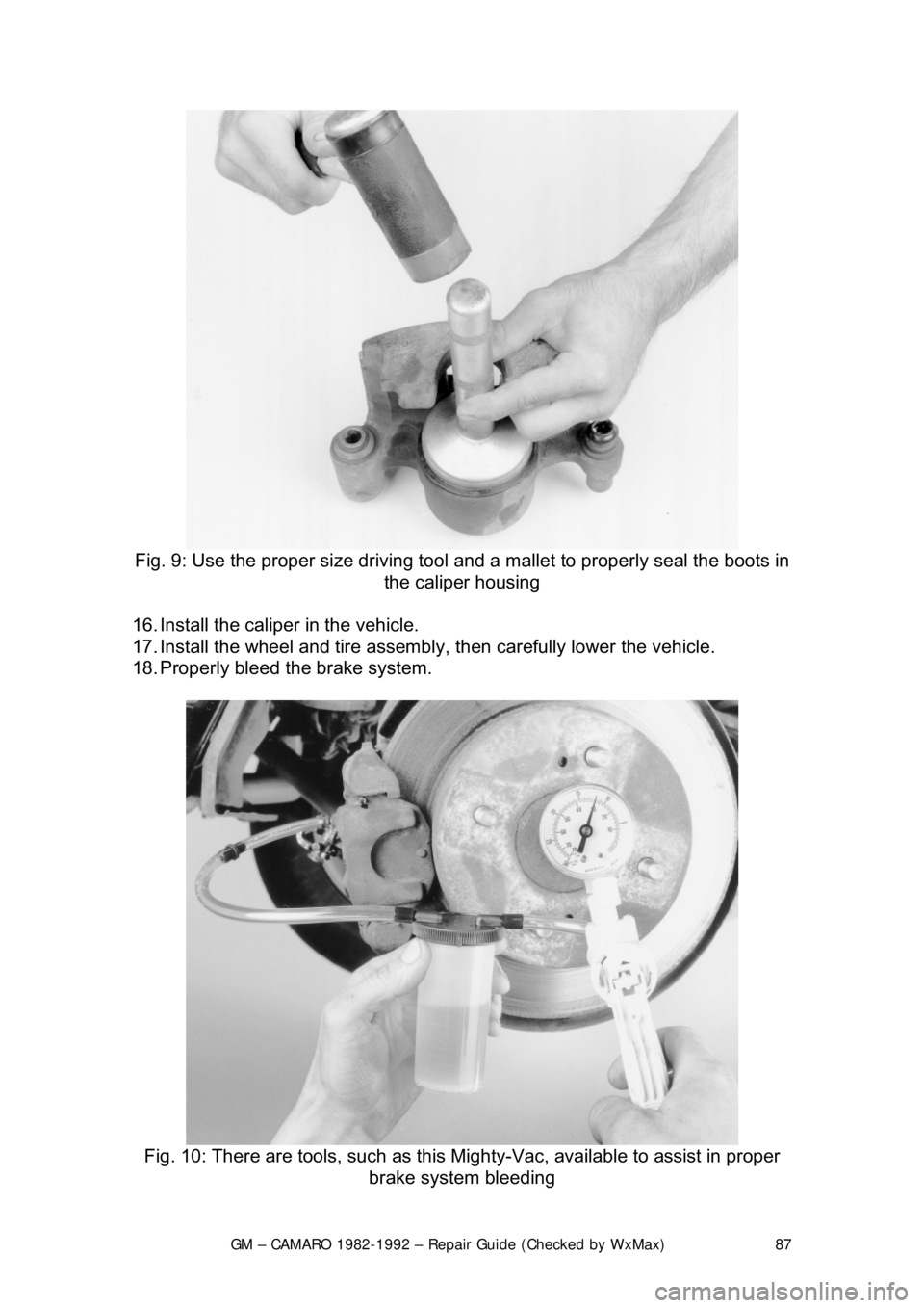
Fig. 9: Use the proper size driving tool and a mallet to properly seal the boots in
the caliper housing
16. Install the caliper in the vehicle.
17. Install the wheel and tire assembly , then carefully lower the vehicle.
18. Properly bleed t he brake system.
Fig. 10: There are tools, such as this Mighty-Vac, available to assist in proper
brake system bleeding
Page 344 of 875

GM – CAMARO 1982-1992 – Repair Guide (Checked by WxMax) 344
ENGINE & ENGINE OVERHAUL
ENGINE ELECTRICAL
ENGINE ELECTRICAL
The engine electrical system can be brok en down into three inter-related, but
distinct systems:
1. The starting system.
2. The charging system.
3. The ignition system.
BATTERY AND STARTING SYSTEM
The battery is the first link in the chai n of mechanisms which work together to
provide cranking of the autom obile engine. In most modern cars, the battery is a
lead-acid electrochemical device consis ting of six two-volt (2V) subsections
connected in series so the unit is c apable of producing approximately 12V of
electrical pressure. Each subsection, or ce ll, consists of a series of positive and
negative plates held a short distance apart in a solution of sulfuric acid and
water. The two types of plates are of di ssimilar metals. This causes a chemical
reaction to be set up, and it is this reacti on which produces current flow from the
battery when its positive and negative te rminals are connected to an electrical
appliance such as a lamp or motor.
The continued transfer of electrons would ev entually convert the sulfuric acid in
the electrolyte to water and make t he two plates identical in chemical
composition. As electrical energy is removed from the battery, its voltage output
tends to drop. Thus, measuring batte ry voltage and battery electrolyte
composition are two ways of checking the ability of the unit to supply power.
During the starting of the eng ine, electrical energy is removed from the battery.
However, if the charging circuit is in good condition and the operating conditions
are normal, the power removed from the battery will be replaced by the
generator (or alternator) which will forc e electrons back through the battery,
reversing the normal flow, and restoring the ba ttery to its original chemical state.
The battery and starting motor are linked by very heavy electrical cable\
s
designed to minimize resistance to the flow of current. Generally, the major
power supply cable that leaves the batte ry goes directly to the starter, while
other electrical system needs are supplied by a smaller cable. During the starter
operation, power flows from the battery to the starter and is grounded through
the car's frame and the batte ry's negative ground strap.
The starting motor is a specially designed, direct current electric motor capable
of producing a very great am ount of power for its size. One thing that allows the
motor to produce a great deal of power is its tremendous rotating speed. It
drives the engine through a ti ny pinion gear (attached to the starter's armature),
which drives the very large flywheel ring gear at a greatly reduced speed.
Another factor allowing it to produce so much power is that only intermittent
Page 359 of 875

GM – CAMARO 1982-1992 – Repair Guide (Checked by WxMax) 359
3. Disconnect all wiring from the star
ter solenoid. Replace each nut as the
connector is removed (as thread sizes differ from connector to
connector). Note or tag the wiring positions for installation.
4. Remove the bracket from the st arter and the two mounting bolts. On
engines with a solenoid heat shield, remove the front bracket upper bolt
and detach the bracket fr om the starter.
5. Remove the front bracket bolt or nut. Lower the starter front end first, and
then remove the unit from the car.
To install: 6. Position the starter into place and se cure it with the front bracket bolt and
nut. Torque the two mounting bolts to 25-35 ft. lbs.
CAUTION - If shims were removed, they must be replaced to ensure proper
pinion-to-flywheel engagement.
7. On engines with a solenoid heat shield, attach the bracket to the starter.
Install the bracket to the starter and the two mounting bolts. Install the
front bracket upper bolt.
8. Connect all wiring to the starte r solenoid and tighten the nuts.
9. Lower the vehicle.
10. Connect the negative battery cable.
SOLENOID REPLACEMENT 1. Remove the screw and washer from the motor connector strap terminal.
2. Remove the two solenoid retaining screws.
3. Twist the solenoid housing clockwis e to remove the flange key from the
keyway in the housing. Then remove the housing.
4. To re-install the unit, place the re turn spring on the plunger and place the
solenoid body on the driv e housing. Turn counterclockwise to engage the
flange key. Place the two retaining screws in position and install the
screw and washer which secures the strap terminal. Install the unit on
the starter.
SENDING UNITS AND SENSORS
For additional information on engine sensors, refer to Engine Performance &
Tune-up and Engine Controls in this repair guide.
Page 492 of 875

GM – CAMARO 1982-1992 – Repair Guide (Checked by WxMax) 492
It is always recommended that you remo
ve any cylinder ridges before removing
the piston and connecting rod assemblies . If you know that new pistons are
going to be installed and the engine bl ock will be bored oversize, you may be
able to forego this step. However, some ridges may actually prevent the
assemblies from being remove d, necessitating its removal.
There are several different types of ridge reamers on the market, none of which
are inexpensive. Unless a great deal of engine rebuild ing is anticipated, borrow
or rent a reamer.
1. Turn the crankshaft until the piston is at the bottom of its travel.
2. Cover the head of the piston with a rag.
3. Follow the tool manufacturers in structions and cut away the ridge,
exercising extreme care to avoid cutting too deeply.
4. Remove the ridge reamer, the r ag and as many of the cuttings as
possible. Continue until all of the cylinder ridges have been removed.
DISASSEMBLY
The engine disassembly instructions fo llowing assume that you have the engine
mounted on an engine stand. If not, it is easiest to disassemble the engine on a
bench or the floor with it resting on t he bellhousing or transmission mounting
surface. You must be able to access the connecting rod fasteners and turn the
crankshaft during disassembly. Also, all en gine covers (timing, front, side, oil
pan, whatever) should have already been removed. Engines which are seized
or locked up may not be able to be co mpletely disassembled, and a core
(salvage yard) engine should be purchased.
If not done during the cylinder head removal, remove the pushrods and li\
fters,
keeping them in order for assembly. Remove the timing gears and/or timing
chain assembly, then remove the oil pu mp drive assembly and withdraw the
camshaft from the engine block. Remove the oil pick-up and pump assembly. If
equipped, remove any balanc e or auxiliary shafts. If necessary, remove the
cylinder ridge from the top of the bore. See the cylinder ridge removal
procedure earlier in this section.
Rotate the engine over so that the cr ankshaft is exposed. Use a number punch
or scribe and mark each connecting rod wit h its respective cylinder number. The
cylinder closest to the front of t he engine is always number 1. However,
depending on the engine placemen t, the front of the engine could either be the
flywheel or damper/pulley end. Generally the front of the engine faces the front
of the vehicle. Use a number punch or scribe and also mark the main bearing
caps from front to rear wit h the front most cap being nu mber 1 (if there are five
caps, mark them 1 through 5, front to rear).
Page 813 of 875

GM – CAMARO 1982-1992 – Repair Guide (Checked by WxMax) 813
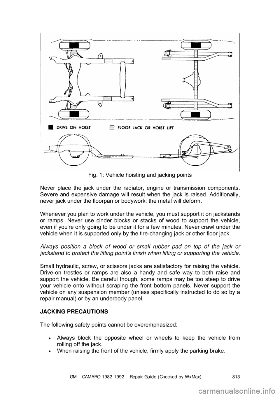
Fig. 1: Vehicle hoisting and jacking points
Never place the jack under the radiator , engine or transmission components.
Severe and expensive damage wil l result when the jack is raised. Additionally,
never jack under the floorpan or body work; the metal will deform.
Whenever you plan to work under the v ehicle, you must support it on jackstands
or ramps. Never use cinder blocks or st acks of wood to support the vehicle,
even if you're only going to be under it for a few minutes. Never crawl under the
vehicle when it is supported only by the tire-changing jack or other floor jack.
Always position a block of wood or smal l rubber pad on top of the jack or
jackstand to protect the lifting point's finish when lifting or supporting the vehicle.
Small hydraulic, screw, or sci ssors jacks are satisfactory for raising the vehicle.
Drive-on trestles or ramps are also a handy and safe way to both raise and
support the vehicle. Be careful though, some ramps may be too steep to drive
your vehicle onto without scraping t he front bottom panels. Never support the
vehicle on any suspension member (unless specifically instructed to do so by a
repair manual) or by an underbody panel.
JACKING PRECAUTIONS
The following safety points cannot be overemphasized:
• Always block the opposite wheel or wheels to keep the vehicle from
rolling off the jack.
• When raising the front of the vehicle, firmly apply the parking brake.