1982 CHEVROLET CAMARO steering
[x] Cancel search: steeringPage 2 of 875

GM – CAMARO 1982-1992 – Repair Guide (Checked by WxMax) 2
This is an essential accessory for do-it
-yourself automotive repair. Each vehicle-
specific guide includes detailed informa tion and graphics to help you get your
car or truck back on the road. Included in most guides: step-by-step instructions
with detailed photographs and drawings, wiring diagrams, specification charts
and repair tips.
1. Body & Trim
2. Brakes
3. Chassis Electrical
4. Drive Train
5. Engine & Engine Overhaul
6. Engine Controls
7. Engine Performance and Tune-up
8. Fuel System
9. General Information & Maintenance
10. Suspension & Steering
Covers all U.S. and Canadian m odels of GM Camaro 1982-1992.
Page 26 of 875

GM – CAMARO 1982-1992 – Repair Guide (Checked by WxMax) 26
Fig. 3: 1991-92 instrument panel
CAUTION - The 1991-92 vehicles are equipped with an Air Bag system. Proper
disarming of the system is necessary before proceeding with any disassembly
or repairs to the steering column, das h or electrical system or possible
deployment of the air bag might occur. Refer to Suspension & Steering for
disarming procedure.
1. Properly disable t he SIR air bag system, if equipped. Disconnect the
negative battery cable.
2. Remove the center console.
3. Remove the screws attaching the in strument panel pad to the instrument
panel.
4. Remove the daytime running light sens or electrical connector, if equipped.
5. Remove the instrument panel pad.
6. Remove the instrument panel sound insulators.
7. Remove the knee bolster and bracket.
8. Remove the instrument panel cluster.
9. Remove the steering column retaining nuts and lower the column.
10. Remove the upper and lower instrument panel to cowl screws.
11. Disconnect and remove the electric al harness at the cowl connector and
under dash panel.
12. Remove the instrument panel assembly.
To install:
13. Install the instru ment panel assembly.
14. Install the electrical harness at the cowl connector and under dash panel.
15. Install the upper and lower inst rument panel to cowl screws.
16. Install the steering column retaining nuts.
17. Install the instru ment panel cluster.
18. Install the knee bolster and bracket.
Page 48 of 875

GM – CAMARO 1982-1992 – Repair Guide (Checked by WxMax) 48
BRAKES
BASIC OPERATING PRINCIPLES
Hydraulic systems are used to actuate t he brakes of all modern automobiles.
The system transports the power required to force the frictional surfaces of the
braking system together from the pedal to the individual brake units at each
wheel. A hydraulic system is used for two reasons.
First, fluid under pressure can be carried to all parts of an automobile by small
pipes and flexible hoses without taking up a significant amount of room or
posing routing problems.
Second, a great mechanical advantage can be given to the brake pedal end of
the system, and the foot pressure requi red to actuate the brakes can be
reduced by making the surface area of t he master cylinder pistons smaller than
that of any of the pistons in t he wheel cylinders or calipers.
The master cylinder consists of a flui d reservoir along with a double cylinder
and piston assembly. Double type master cylinders are designed to separate
the front and rear braking systems hydraulic ally in case of a leak. The master
cylinder coverts mechanical motion from t he pedal into hydraulic pressure within
the lines. This pressure is translated back into mechanical motion at th\
e wheels
by either the wheel cylinder (drum brak es) or the caliper (disc brakes).
Steel lines carry the brake fluid to a po int on the vehicle's frame near each of
the vehicle's wheels. The fluid is then ca rried to the calipers and wheel cylinders
by flexible tubes in order to allow for suspension and steering movements.
In drum brake systems, each wheel cylinde r contains two pistons, one at either
end, which push outward in opposite direct ions and force the brake shoe into
contact with the drum.
In disc brake systems, the cylinders ar e part of the calipers. At least one
cylinder in each caliper is used to fo rce the brake pads against the disc.
All pistons employ some type of seal, us ually made of rubber, to minimize fluid
leakage. A rubber dust boot seals the outer end of the cylinder against dust and
dirt. The boot fits around the outer end of the piston on disc brake calipers, and
around the brake actuating rod on wheel cylinders.
The hydraulic system operates as follows : When at rest, the entire system, from
the piston(s) in the master cylinder to t hose in the wheel cylinders or calipers, is
full of brake fluid. Upon app lication of the brake pedal, fluid trapped in front of
the master cylinder piston(s) is forced through the lines to the wheel cylinders.
Here, it forces the pistons outward, in the case of drum brakes, and inward
toward the disc, in the case of disc brakes. The motion of the pistons is
opposed by return springs mounted outside the cylinders in drum brakes, and
by spring seals, in disc brakes.
Page 73 of 875

GM – CAMARO 1982-1992 – Repair Guide (Checked by WxMax) 73
To install:
9. Install the new line or hose, starti
ng with the end farthest from the master
cylinder. Connect the other end, then confirm that both fittings are correctly
threaded and turn smoothly using finger pressure. Make sure the new line
will not rub against any ot her part. Brake lines must be at least 1/2 in.
(13mm) from the steering column and other moving parts. Any protective
shielding or insulators must be rein stalled in the original location.
WARNING - Make sure the hose is NO T kinked or touching any part of the
frame or suspension after installation. These conditions may cause the hose to
fail prematurely.
10. Using two wrenches as bef ore, tighten each fitting.
11. Install any retaining clips or brackets on the lines.
12. If removed, install the wheel and tire assemblies, then carefully lower the
vehicle to the ground.
13. Refill the brake master cylinder re servoir with clean, fresh brake fluid,
meeting DOT 3 specifications. Pr operly bleed the brake system.
14. Connect the negative battery cable.
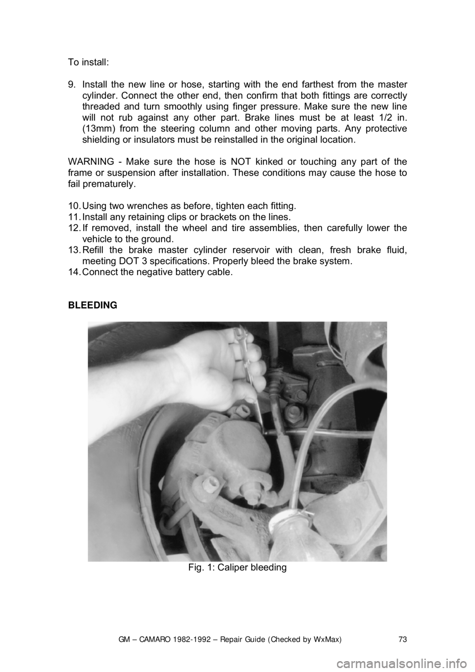
BLEEDING
Fig. 1: Caliper bleeding
Page 80 of 875

GM – CAMARO 1982-1992 – Repair Guide (Checked by WxMax) 80
4. Remove the mounting bo
lts, if equipped with single piston caliper or the
circlip and pin, if equipped with dual piston ca liper. Inspect the bolts for
corrosion and replace as necessary.
5. Remove the caliper fr om the steering knuckle an d suspend it from the body
of the car with a length of wire. Do not allow the caliper to hang by its hose.
6. Remove the pad retaining springs and remove the pads from the caliper.
7. Remove the plastic sleeves and the rubber bushings from the mounting bolt
holes.
8. Obtain a pad replacem ent kit. Lubricate and install the new sleeves and
bushings with a light coat of silicone grease.
9. Install the retainer spring on the i nboard pad, if equipped with single piston
caliper.
A new spring should be included in the pad replacement kit.
10. Install the new inboard pad into the caliper with the wear sensor at the
leading end of the shoe duri ng forward wheel rotation.
11. Install the outboard pad into the caliper.
12. Use a large pair of slip joint plie rs to bend the outer pad ears down over the
caliper, if equipped with t he single piston caliper.
13. Install the calip er onto the steering knuckle. Tighten the mounting bolts to
21-35 ft. lbs. (28-47 Nm), if equipped. In stall the wheel and lower the car. Fill
the master cylinder to its proper le vel with a good quality brake fluid.
14. Pump the brake pedal slowly a nd firmly 3 times with the engine running
before attempting to move the vehicle; bleed the brakes as required.
BRAKE CALIPER
CAUTION - Some brake pads contain asbest os, which has been determined to
be a cancer causing agent. Never clean the brake surfaces with compressed
air! Avoid inhaling any dust from any brake surface! When cleaning brake
surfaces, use a commercially available brake cleaning fluid.
REMOVAL & INSTALATION
Page 91 of 875

GM – CAMARO 1982-1992 – Repair Guide (Checked by WxMax) 91
Avoid inhaling any dust from
any brake surface! When cleaning brake surfaces,
use a commercially available brake cleaning fluid.
1. Remove the caliper by following instru ctions of caliper removal procedure.
2. Remove dust cap, cotter pin, castle nut, thrust washer and outside wheel
bearing. Pull the disc/hub assembly from the steering knuckle.
To install:
3. Position the disc/hub assembly to t he spindle/steering knuckle. Install the
outside wheel bearing, thru st washer and castle nut. Tighten the castle nut
until the bearing is s nug. Back off the nut
1/4 turn. Refer to Suspension &
Steering for details on wheel bearing remo val, installation, and adjustment.
Install a new cotter pin and dust cap.
4. Install the brake caliper.
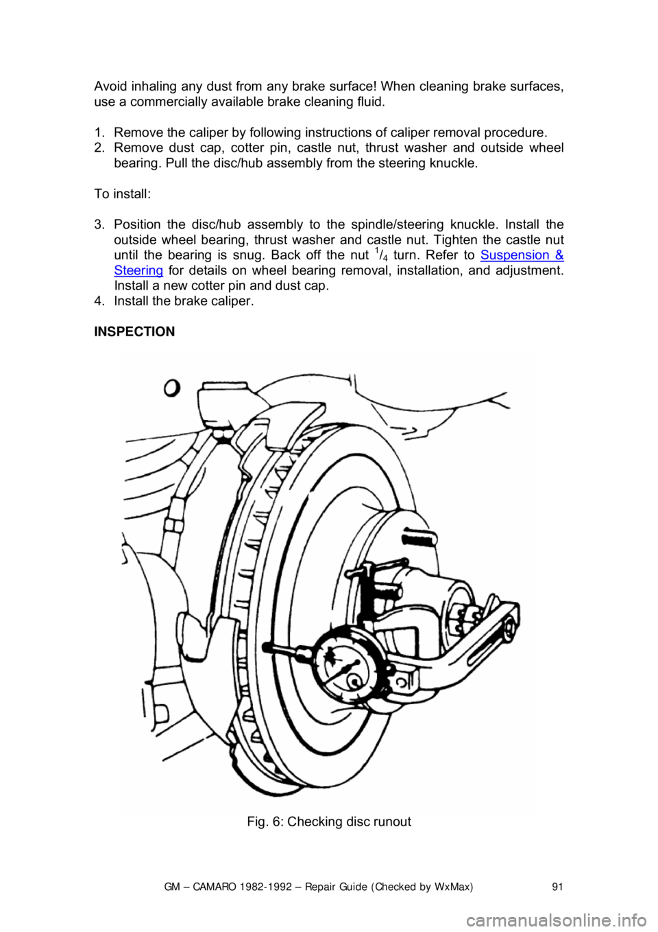
INSPECTION
Fig. 6: Checking disc runout
Page 146 of 875

GM – CAMARO 1982-1992 – Repair Guide (Checked by WxMax) 146
SUPPLEMENTAL INFLATABLE RESTRAINT SYSTEM
GENERAL INFORMATION
All 1990-1992 models are equi
pped with an airbag system. The Supplemental
Inflatable Restraint (SIR) syst em helps supplement the protection offered by the
seat belts by deploying an ai r bag from the center of the steering wheel. The air
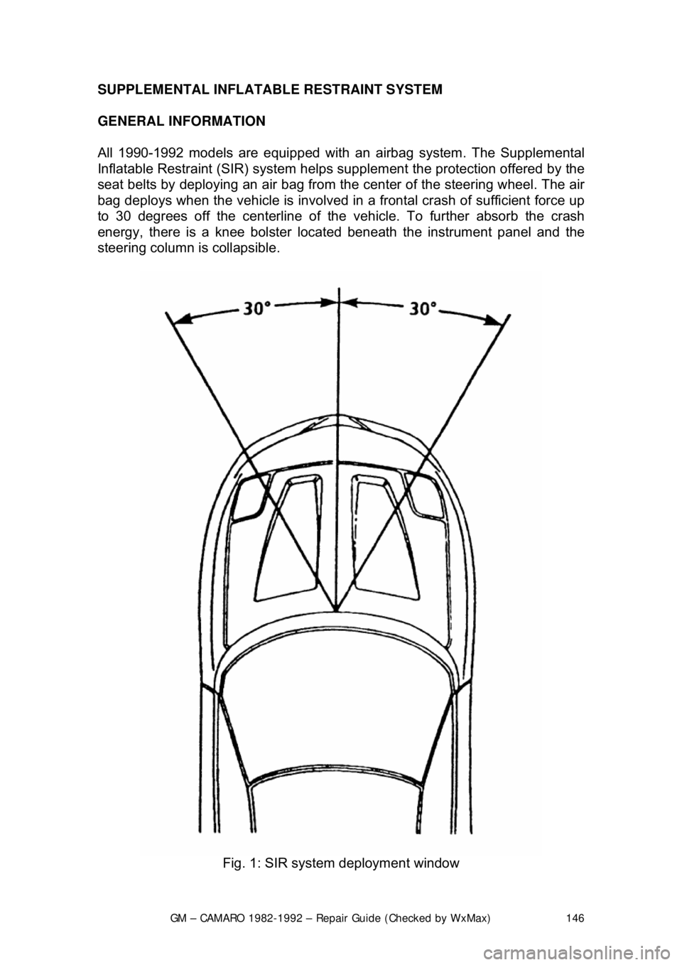
bag deploys when the vehicle is involved in a frontal crash of sufficient force up
to 30 degrees off the center line of the vehicle. To further absorb the crash
energy, there is a knee bolster located beneath the instrument panel and the
steering column is collapsible.
Fig. 1: SIR system deployment window
Page 148 of 875

GM – CAMARO 1982-1992 – Repair Guide (Checked by WxMax) 148
ARMING SENSOR
The arming sensor is a protective switch
located in the power feed side of the
deployment loop. It is calibrated to clos e at low level velocity changes (lower
than the discriminating sens ors). This assures that the inflator module is
connected directly to the 36 volt output of the DERM or battery voltage feed
when either of the discrim inating sensors close.
DISCRIMINATING SENSORS
The discriminating sensors are wired in parallel on the ground side of the
deployment loop. These sensors are calib rated to close with velocity changes
which are severe enough to warrant deployment.
SIR COIL ASSEMBLY
The SIR coil assembly consists of two cu rrent carrying coils. They are attached
to the steering column and allow rotation of the steering wheel while maintaining
continuous contact of the deployment loop to the inflator module.
INFLATOR MODULES
Each inflator module consists of an inflat able bag and an inflator (a canister of
gas generating material with an initiati ng device). When the vehicle is in a
frontal crash of sufficient force, current flows through the deployment loops.
Current flowing through the initiator ignite s the material in the inflator module.
The gas produced from this reaction rapidly inflates the air bag.
Fig. 2: Forward discriminating se nsor location on 1990-1992 models