1982 CHEVROLET CAMARO steering
[x] Cancel search: steeringPage 802 of 875

GM – CAMARO 1982-1992 – Repair Guide (Checked by WxMax) 802
BODY LUBRICATION
HOOD LATCH AND HINGES
Clean the latch surfaces and
apply clean engine oil to the latch pilot bolts and
the spring anchor. Use the engine oil to l ubricate the hood hinges as well. Use a
chassis grease to lubricate all the pivot points in the latch release mechanism.
DOOR HINGES
The gas tank filler door, car door, and rear hatch or trunk lid hinges should be
wiped clean and lubricated with clean engi ne oil. Silicone spray also works well
on seals, but must be applied more often. Use engine oil to lubricate the trunk
or hatch lock mechanism and the lock bo lt and striker. The door lock cylinders
can be lubricated easily with a shot of silicone spray or one of the many dry
penetrating lubricants commercially available.
PARKING BRAKE LINKAGE
Use chassis grease on the parking brake c able where it contacts the guides,
links, levers, and pulleys. The grease s hould be water resistant for durability.
ACCELERATOR LINKAGE
Lubricate the throttle lever, and the accele rator pedal lever at the support inside
the car with clean engine oil.
TRANSMISSION SHIFT LINKAGE
Lubricate the shift linkage with water re sistant chassis grease which meets GM
Specification 6031M or its equal.
FRONT WHEEL BEARINGS
Once every 30,000 miles, clean and repack wheel bearings with a wheel
bearing packer. Remove any excess grea se from the exposed surface of the
hub and seal.
REMOVAL, REPACKING, INSTA LLATION AND ADJUSTMENT
WARNING - It is important that wheel b earings be properly adjusted after
installation. Improperly adj usted wheel bearings can c ause steering instability,
front end shimmy and wander, and increased tire wear.
1. Raise the car and support it at the lower arm. Remove the tire and wheel
assembly.
2. Remove the brake caliper and support it on a wire.
3. Remove the dust cap, cotter pin, ca stle nut, thrust washer and outside
wheel bearing.
4. Pull the disc/hub assembly from the steering knuckle.
Page 803 of 875

GM – CAMARO 1982-1992 – Repair Guide (Checked by WxMax) 803
5. Pry out the inner seal and
remove the inner bearing.
6. Wipe out the grease from inside the hub.
7. Clean the wheel bearings thor oughly with solvent and check their
condition before installation. Afte r cleaning, check parts for excessive
wear and replace damaged parts.
WARNING - Do not allow the bearing to spin when blowing dry with
compressed air, as this would allow t he bearing to turn without lubrication.
8. Apply a sizable amount of lubricant to the palm of one hand. Using your
other hand, work the bearing into the lubricant so that the grease is
pushed through the rollers and out t he other side. Keep rotating the
bearing while continuing to push the lubricant through it.
9. Apply grease to the inside of t he hub and install the inner bearing in the
hub. Install a new grease seal, be careful not to damage the seal.
10. Install the disc/hub assembly onto t he steering knuckle. Install the outer
bearing, thrust washer and castle nu t. Torque the nut to 12 ft. lbs. (16
Nm) while turning the wheel.
11. Back the nut off and retighten it by hand until nearest slot aligns with the
cotter pin hole.
12. Insert a new cotter pin.
13. Mount a dial indicator onto the vehi cle so that any end-play in the hub
can be measured. Measure the end-play and record the value. End-play
should be between 0.001-0.005 in. (0.025- 0.127mm). If play exceeds this
tolerance, the wheel bearings should be replaced.
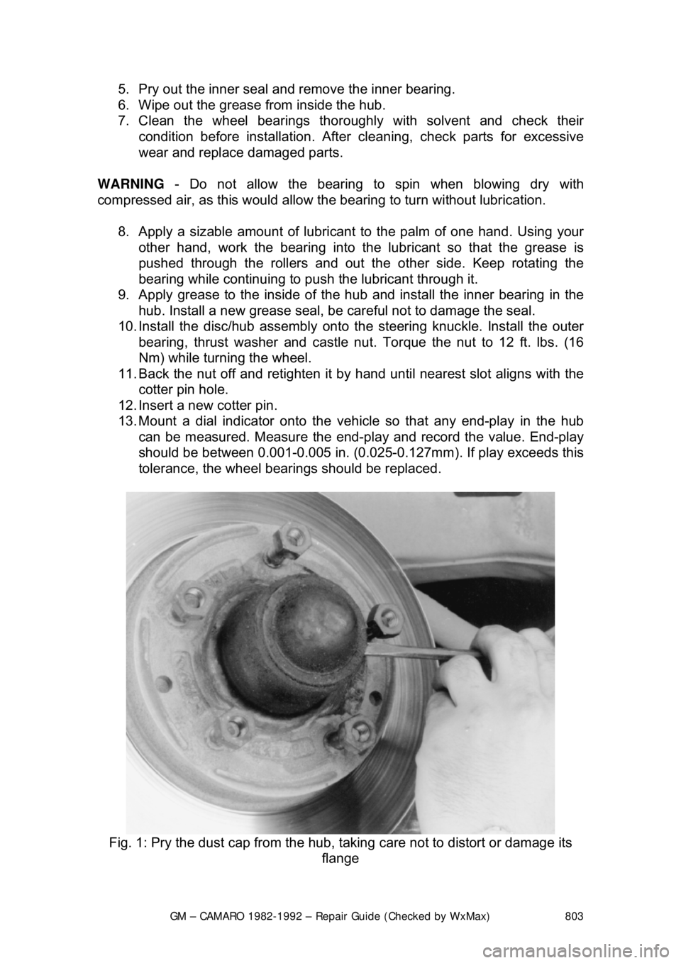
Fig. 1: Pry the dust cap fr om the hub, taking care not to distort or damage its
flange
Page 817 of 875

GM – CAMARO 1982-1992 – Repair Guide (Checked by WxMax) 817
SUSPENSION & STEERING
SUSPENSION AND STEERING WHEELS
REMOVAL & INSTALLATION
• Park the vehicle on a level surface.
• Remove the jack, tire iron and, if nec essary, the spare tire from their
storage compartments.
• Check the owner's manual or refer to General Information & Maintenance
of this repair guide for the jacking poi nts on your vehicle. Then, place the
jack in the proper position.
• If equipped with lug nut trim caps, remo ve them by either unscrewing or
pulling them off the lug nuts, as appr opriate. Consult the owner's manual,
if necessary.
• If equipped with a wheel cover or hub c ap, insert the tapered end of the
tire iron in the groove and pry off the cover.
1. Apply the parking brake and block the diagonally opposite wheel with a
wheel chock or two.
Wheel chocks may be purchased at your lo cal auto parts store, or a block of
wood cut into wedges may be used. If possi ble, keep one or two of the chocks
in your tire storage compartment, in case any of the tires has to be removed on
the side of the road.
2. If equipped with an automatic transmi ssion, place the selector lever in P
or Park; with a manual transmission, place the shifter in Reverse.
3. With the tires still on the ground, use the tire iron/wrench to break the lug
nuts loose.
If a nut is stuck, never use heat to loosen it or damage to the wheel and
bearings may occur. If the nuts are seized, one or two heavy hammer blows
directly on the end of the bol t usually loosens the rust. Be careful, as continued
pounding will likely damage the brake drum or rotor.
3. Using the jack, raise the vehicle unt il the tire is clear of the ground.
Support the vehicle safely using jackstands.
4. Remove the lug nuts, then remove the tire and wheel assembly.
To install:
5. Make sure the wheel and hub mating su rfaces, as well as the wheel lug
studs, are clean and free of all foreign material. Always remove rust from
the wheel mounting surfac e and the brake rotor or drum. Failure to do so
may cause the lug nuts to loosen in service.
6. Install the tire and wheel asse mbly and hand-tighten the lug nuts.
7. Using the tire wrench, tighten all the lug nuts, in a crisscross pattern, until
they are snug.
8. Raise the vehicle and withdraw the jackstand, then lower the vehicle.
Page 824 of 875

GM – CAMARO 1982-1992 – Repair Guide (Checked by WxMax) 824
1982-92 Camaros are equipped wit
h a front suspension consisting of a pivoting
lower control arm on which are mounted a coil spring and a MacPherson strut.
The strut and spring are separate. The spring upper end bears on a fixed
crossmember; the strut upper end is loca ted in a strut tower on the fender.
COIL SPRINGS
REMOVAL & INSTALLATION
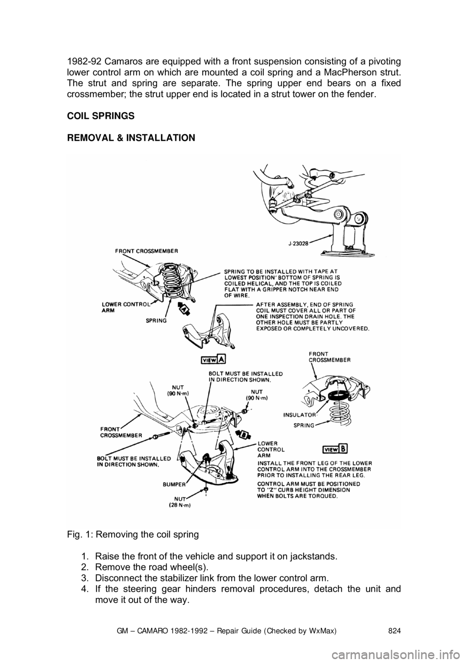
Fig. 1: Removing the coil spring
1. Raise the front of the vehi cle and support it on jackstands.
2. Remove the road wheel(s).
3. Disconnect the stabilizer link from the lower control arm.
4. If the steering gear hinders remova l procedures, detach the unit and
move it out of the way.
Page 825 of 875

GM – CAMARO 1982-1992 – Repair Guide (Checked by WxMax) 825
5. Disconnect the tie rod from the
steering knuckle using a ball joint
remover.
6. Using an internal fit coil spring co mpressor, compress the coil spring so
that it is loose in its seat.
CAUTION - Be sure to follow manufacturer' s instructions when using spring
compressor. Coil springs in a comp ressed state contain enormous energy
which, if released accidentally, could cause serious injury.
7. To remove the coil spring, disc onnect the lower control arm from the
crossmember at the pivot bolts. If additional clearance is necessary,
disconnect the lower control arm from the steering knuckle at the ball
joint.
To install: 8. Compress the coil spring until spri ng height is the same as when
removed, then position the spring on the control arm. Make sure the
lower end of the coil spring is properly positioned in the lower control arm
and that the upper end fits correctly in its pad.
9. Connect the lower control arm from t he steering knuckle at the ball joint.
Connect the lower control arm from t he crossmember at the pivot bolts
and install the coil spring.
10. Connect the tie rod to the steering knuckle.
11. Attach the steering gear unit.
12. Connect the stabilizer link to the lower control arm.
13. Install the wheel(s).
14. Lower the vehicle.
Page 828 of 875

GM – CAMARO 1982-1992 – Repair Guide (Checked by WxMax) 828
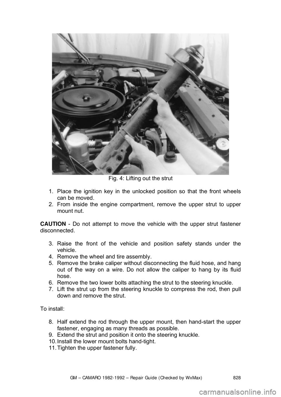
Fig. 4: Lifting out the strut
1. Place the ignition key in the unlock ed position so that the front wheels
can be moved.
2. From inside the engine compartm ent, remove the upper strut to upper
mount nut.
CAUTION - Do not attempt to move the ve hicle with the upper strut fastener
disconnected.
3. Raise the front of the vehicl e and position safety stands under the
vehicle.
4. Remove the wheel and tire assembly.
5. Remove the brake caliper without disconnecting the fluid hose, and hang
out of the way on a wire. Do not allo w the caliper to hang by its fluid
hose.
6. Remove the two lower bolts attachi ng the strut to the steering knuckle.
7. Lift the strut up from the steering k nuckle to compress the rod, then pull
down and remove the strut.
To install: 8. Half extend the rod through th e upper mount, then hand-start the upper
fastener, engaging as many threads as possible.
9. Extend the strut and position it onto the steering knuckle.
10. Install the lower mount bolts hand-tight.
11. Tighten the upper fastener fully.
Page 829 of 875

GM – CAMARO 1982-1992 – Repair Guide (Checked by WxMax) 829
12. Fully tighten the lower bolts onl
y when the front suspension is on the
ground. Torque the steering knuckle-to-strut nuts to 125 ft. lbs. (170 Nm)
followed by a 120 degree turn. Do not exceed a final torque of 148 Ft.
lbs. (200 Nm).
13. Install the brake caliper
14. Install the wheel and tire assembly.
15. Lower the front of the vehicle.
16. From inside the engine compartm ent, tighten the upper strut to upper
mount nut to 44 ft. lbs. (60 Nm).
17. Have the front end aligned.
OVERHAUL
The OEM domestic struts are serviced by replacement of the entire unit. There
is no strut cartridge to replace.
LOWER BALL JOINT
INSPECTION
Before performing this inspection, make sure the wheel bearings are adjusted
correctly and that the control arm bushings are in good condition.
1. Jack the car up under the front lower control arm at the spring seat.
2. Raise the car until t here is 1-2 in. (25-51mm) of clearance under the
wheel.
3. Insert a bar under the wheel and pr y upward. If the wheel raises more
than
1/8 in. (3mm), the ball joints are worn. Determine if the lower ball
joint is worn by visual inspec tion while prying on the wheel.
REMOVAL & INSTALLATION
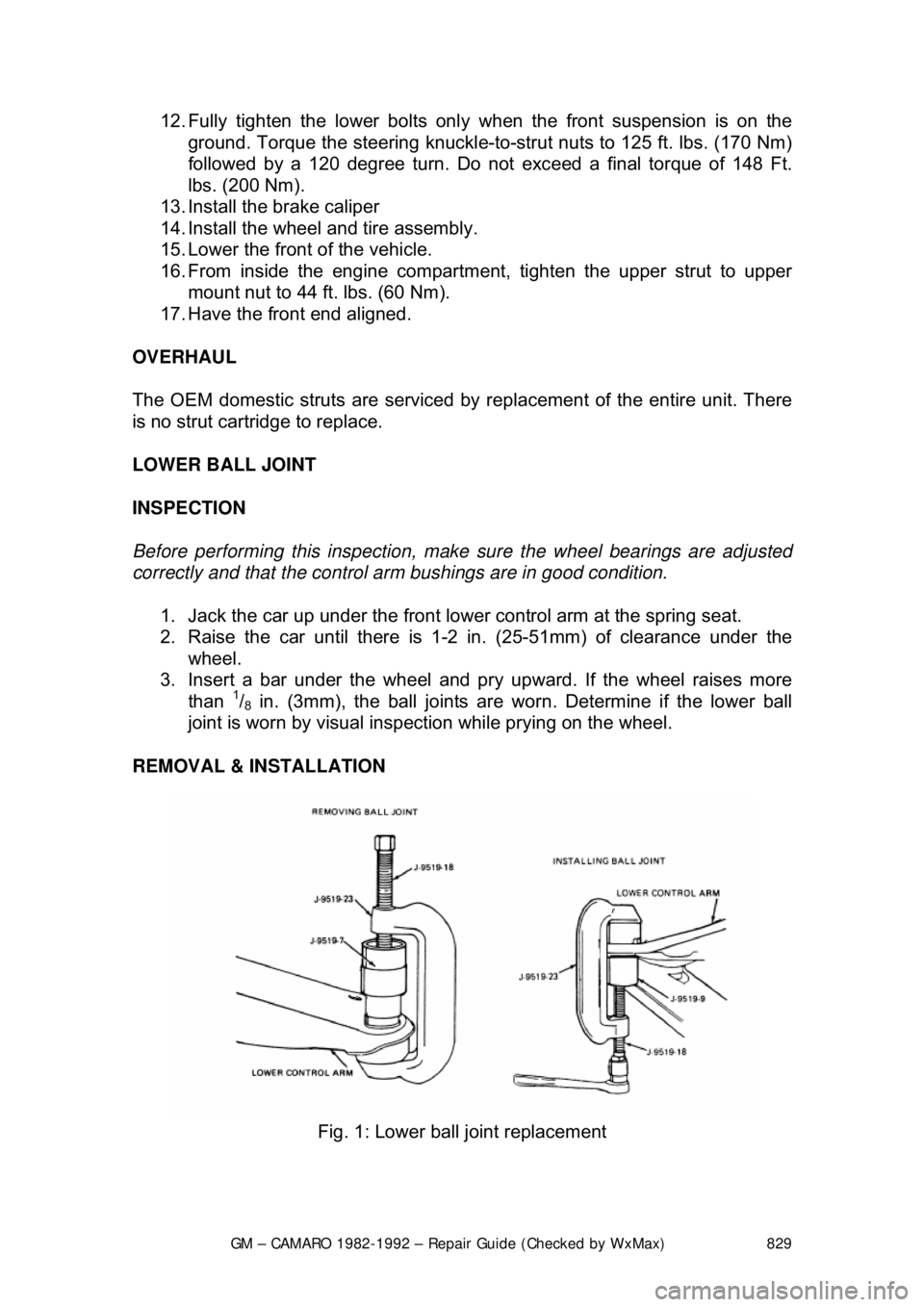
Fig. 1: Lower ball joint replacement
Page 830 of 875

GM – CAMARO 1982-1992 – Repair Guide (Checked by WxMax) 830
To prevent component dam
age, an on-car ball joint press, such as Kent-Moore
tool J-9519-23 should be used.
1. Raise and safely support the vehicle, then remove the wheel.
2. Support the lower control arm spring seat with a jack.
3. Loosen the lower ball stud nut. Break the ball stud loose. Remove the
ball stud nut.
4. Remove the ball stud from the steering knuckle. Support the steering
knuckle aside using a hanger or wire.
5. Using a ball joint press, remove the ball joint from the lower control arm.
To install: 6. Install the new ball joint, using the press.
7. Install the ball stud in the steering knuckle boss.
8. Install the nut on the ball stud, ti ghtening to 77 ft. lbs. (105 Nm) on all
models. Continue to tighten the nut until the cotter pin holes align and
install the pin. Do not back o ff the nut to align the holes.
9. Install the lube fitting and grease the new joint.