Page 856 of 875

GM – CAMARO 1982-1992 – Repair Guide (Checked by WxMax) 856
1. Properly disable the SIR
air bag system, if equipped.
2. Place the lock in the Run position.
3. Remove the lock plate, turn signal switch and buzzer switch.
4. Remove the screw and lock cylinder.
CAUTION - If the screw is dropped on removal, it could fall into the column,
requiring complete disassembly to retrieve the screw.
To install:
5. Rotate the cylinder clockwise to a lign cylinder key with the keyway in the
housing.
6. Push the lock all the way in.
7. Install the screw. Tighten the screw to 14 inch lbs. (1.5 Nm) for
adjustable columns and 25 inch lbs. (2.8 Nm) for standard columns. Re-
center the SIR coil assembly as previously directed.
STEERING COLUMN
WARNING - Before attempting any repairs involving the steering wheel or
disassembly of it, ensure that the Supple mental Inflatable Restraint (Air Bag)
system is properly disarmed.
REMOVAL & INSTALLATION
The front of the dash mount ing plates must be loosened whenever the steering
column is to be lowered from the instrument panel.
1. Disconnect the negative battery cable.
2. On 1990-92 vehicles, disable the S upplemental Inflatable Restraint (SIR)
system as follows: a. Turn the steering wheel so th e vehicle's wheels are pointing
straight-ahead.
The wheels of the vehicle must be in the straight-ahead position
and the steering column in the locked position before proceeding
with steering column remo val. Failure to follow this procedure will
cause the SIR coil to become uncentered, resulting in damage to
the coil assembly.
b. Remove the SIR fuse from the fuse block.
c. Remove the left sound insulator by removing the nut from the stud
and gently prying the insulator from the knee bolster.
d. Disconnect the Connector Position Assurance (CPA) and yellow 2-way SIR harness connector at the base of the steering column.
3. Remove the nut and bolt from t he upper intermediate shaft coupling.
Separate the coupling from the lo wer end of the steering column.
4. Remove the steering w heel, if the column is to be replaced or repaired
on the bench.
5. Remove the knee bolster and bracket, if equipped.
Page 857 of 875

GM – CAMARO 1982-1992 – Repair Guide (Checked by WxMax) 857
6. Remove the bolts attaching the toe plate to the cowl.
7. Disconnect the electrical connectors.
8. Remove the capsule nuts attachi
ng the steering column support bracket
to the instrument panel.
9. Disconnect the park lock cable from the ignition switch inhibitor, if
equipped with automatic transmission.
10. Remove the steering column from the vehicle.
To install:
If a replacement steering column is bein g installed, do not remove the anti-
rotation pin until after the steering co lumn has been connected to the steering
gear. Removing the anti-rotation pin before the steering column is connected to
the steering gear may dam age the SIR coil assembly.
11. Position the steering column in the vehicle.
12. Connect the park lock cable to the ig nition switch inhibitor on vehicles
with automatic transmission.
13. Install the capsule nuts attaching the steering column support bracket to
the instrument panel and tighten to 20 ft. lbs. (27 Nm).
14. Install the nut and bolt to the upper intermediate shaft coupling attaching
the upper intermediate shaft to the steer ing column. Tighten the nut to 44
ft. lbs. (60 Nm).
15. Install the bolts attaching the toe pl ate to the cowl and tighten to 58 inch
lbs. (6.5 Nm).
16. Connect the electrical connectors.
17. Remove the anti-rotation pin if a se rvice replacement steering column is
being installed.
18. Install the knee bolster and bracket, if equipped.
19. Install the sound insulator panel.
If SIR coil has become uncentered by turni ng of the steering wheel without the
column connected to the st eering gear, follow the proper adjustment procedure
for the SIR coil assembly before proceeding.
20. Install the steering wheel.
21. Connect the negative battery cable.
22. Enable the SIR system as follows: a. Connect the yellow 2-way SIR harness connector to the base of
the steering column and CPA clip and install the SIR fuse.
b. Install the left sound insulator.
c. Turn the ignition switch to the RUN position and verify that the
inflatable restraint indicator fl ashes 7-9 times and then turns OFF.
If the indicator does not respond as stated, a problem within the
SIR system is indicated.
Page 858 of 875
GM – CAMARO 1982-1992 – Repair Guide (Checked by WxMax) 858
STEERING GEAR, PUMP AND LINKAGE
STEERING LINKAGE
Fig. 1: Steering linka ge (exploded view)
Page 862 of 875

GM – CAMARO 1982-1992 – Repair Guide (Checked by WxMax) 862
During production, the installe
d position of the relay rod is carefully controlled to
assure that the rod is at the proper height. Both the left end and the right end of
the relay rod must be held at the sa me height. The side-to-side height is
controlled by adjusting the pos ition of the idler arm
Whenever disconnecting the rela y rod assembly, it is important to first scribe the
position of the idler arm-to-frame, and to reinstall the idler arm in the same
position. Be sure to prevent the idler support from turning in the bushing, since
that motion could result in improper relay rod height.
Whenever replacing the relay rod, or the idler arm, or the Pitman arm, it is
mandatory to establish the correct height.
1. Raise the vehicle and support safely on jackstands.
2. Remove the inner ends of the tie rods from the relay rod.
3. Remove the nut from the relay rod ball stud attachment at Pitman arm.
4. Detach the relay rod from the Pitm an arm by using tool such as J-24319-
01 or equivalent. Shift the steering lin kage as required to free the Pitman
arm from the relay rod.
5. Remove the nut from the idler arm and remove the relay rod from the
idler arm.
To install: 6. Install the relay rod to idler arm, ma king certain idler stud seal is in place.
Use J-29193 or J-29194 or equivalent to seat the tapers. A torque of 15
ft. lbs. (20 Nm) is required. With the tapers seated, remove the tool, then
install a prevailing torque nut, and ti ghten to 35 ft. lbs. (48 Nm).
7. Raise the end of the rod and insta ll on the Pitman arm. Use J-29193 or J-
29194 or equivalent to seat the tapers. A torque of 15 ft. lbs. (20 Nm) is
required. With the tapers seated, remove the tool, then install a prevailing
torque nut, and tighten to 35 ft. lbs. (48 Nm).
8. Install the tie rod ends to the re lay rod. Lubricate the tie rod ends.
9. Install the damper , if equipped.
10. Set the relay rod height. Torque t he idler arm-to-frame mounting bolts to
61 ft. lbs. (83 Nm).
11. Lower the vehicle.
12. Check and, if necessary, adjust front end alignment.
Page 863 of 875
GM – CAMARO 1982-1992 – Repair Guide (Checked by WxMax) 863
TIE ROD ENDS
Fig. 6: Using a tie rod removal tool
1. Raise the vehicle and support safely on jackstands.
2. Remove the cotter pins from the ball studs and remove the castellated
nuts.
3. Remove the outer ball stud by usi ng the ball stud puller. If necessary, pull
downward on the tie rod to disconnec t it from the steering arm.
4. Remove the inner ball stud from the relay rod using a similar procedure.
5. Remove the tie rod end or ends to be replaced by loosening the clamp
bolt and unscrewing them.
To install: 6. Lubricate tie rod threads with chassi s grease and install new tie rod(s).
Make sure both ends are an equal di stance from the tie rod and tighten
clamp bolts.
7. Make sure ball studs, tapered surf aces, and all threaded surfaces are
clean and smooth, and free of grease. Install seals on ball studs. Install
ball stud in steering arm and relay rod.
Page 864 of 875

GM – CAMARO 1982-1992 – Repair Guide (Checked by WxMax) 864
8. Rotate both inner and out
er tie rod housings rearward to the limit of ball
joint travel before tightening clamps . Make sure clamp slots and sleeve
slots are aligned before tightening cl amps. Make sure tightened bolts will
be in horizontal position to 45 degrees upward (in the forward direction)
when the tie rod is in its normal positi on. Make sure the tie rod end stays
in position relative to the rod duri ng the tightening operation. Tighten the
clamps, and then return the assembly to the center of its travel.
9. Install ball stud nuts and torque to 35 ft. lbs. (47 Nm) Then tighten (do not
loosen) further as required to align cotter pin holes in studs and nuts.
Install new cotter pins.
10. Lubricate new tie rod ends and lower the vehicle.
POWER STEERING GEAR
ADJUSTMENTS
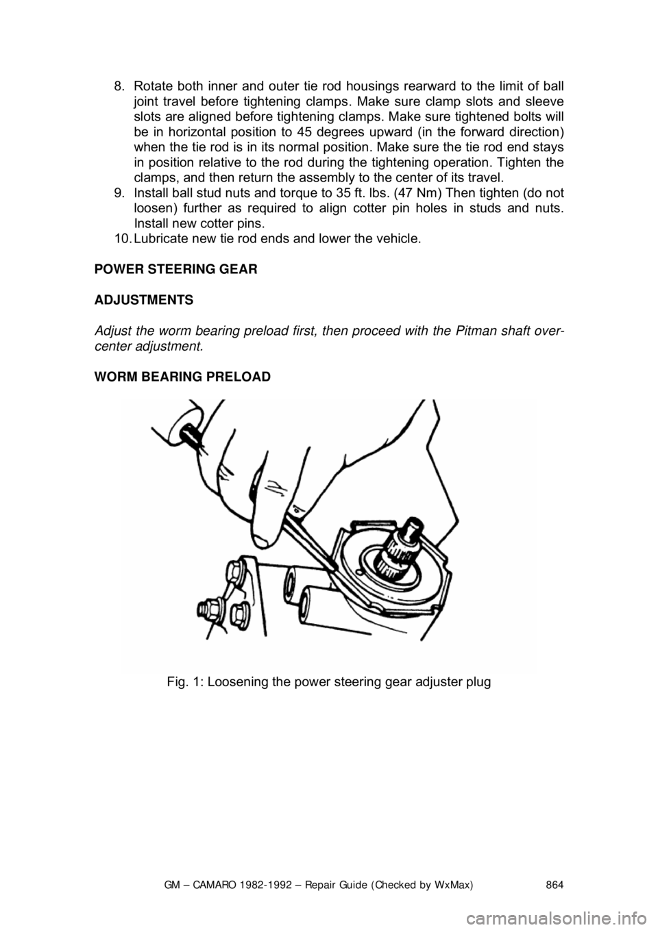
Adjust the worm bearing preload first, then proceed with the Pitman shaft over-
center adjustment.
WORM BEARING PRELOAD
Fig. 1: Loosening the power steering gear adjuster plug
Page 866 of 875

GM – CAMARO 1982-1992 – Repair Guide (Checked by WxMax) 866
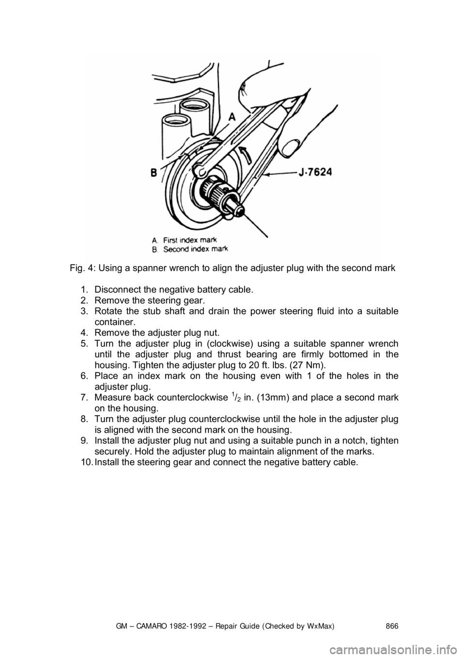
Fig. 4: Using a spanner wrench to align the adjuster plug with the second mark
1. Disconnect the negative battery cable.
2. Remove the steering gear.
3. Rotate the stub shaft and drain the power steering fluid into a suitable
container.
4. Remove the adjuster plug nut.
5. Turn the adjuster plug in (clock wise) using a suitable spanner wrench
until the adjuster plug and thrust bearing are firmly bottomed in the
housing. Tighten the adjuster plug to 20 ft. lbs. (27 Nm).
6. Place an index mark on the housi ng even with 1 of the holes in the
adjuster plug.
7. Measure back counterclockwise
1/2 in. (13mm) and place a second mark
on the housing.
8. Turn the adjuster plug counterclock wise until the hole in the adjuster plug
is aligned with the second mark on the housing.
9. Install the adjuster plug nut and using a suitable punch in a notch, tighten
securely. Hold the adjuster plug to ma intain alignment of the marks.
10. Install the steering gear and c onnect the negative battery cable.
Page 867 of 875
GM – CAMARO 1982-1992 – Repair Guide (Checked by WxMax) 867
Pitman Shaft Over-Center
Fig. 5: Aligning the stub sha ft parallel with the top cover
Fig. 6: Checking the over-center rotational torque
1. Disconnect the negative battery cable.
2. Remove the steering gear.